When you click on links to various merchants on this site and make a purchase, this can result in this site earning a commission. Affiliate programs and affiliations include, but are not limited to, the eBay Partner Network.
DIY Supplemental: AJ126 3.0L V6 Cylinder Head Removal
Time for me to return the favor and give back to the community in which I've been able to take valuable information and feedback from. This will not serve as a comprehensive DIY guide for the cylinder head removal process, but as centralized information and supplemental info to the Factory Workshop manual/ existing DIY's that cover things like S/C removal, ignition, Injectors, etc that need to be removed to get to the timing system or head removal.
The Tragedy:
A leaky valve cover gasket is what prompted me to do the usual overhaul maintenance on the F type (coolant pipes, S/C coupler, Injector service, gaskets, etc) but that was the basis to remove the injectors. Long story short, 5 of 6 injectors came out with very minimal effort, but the 6th proved to be the end of that dream. It was cylinder #4 injector that was completely seized, which is the first cylinder on the LH bank.
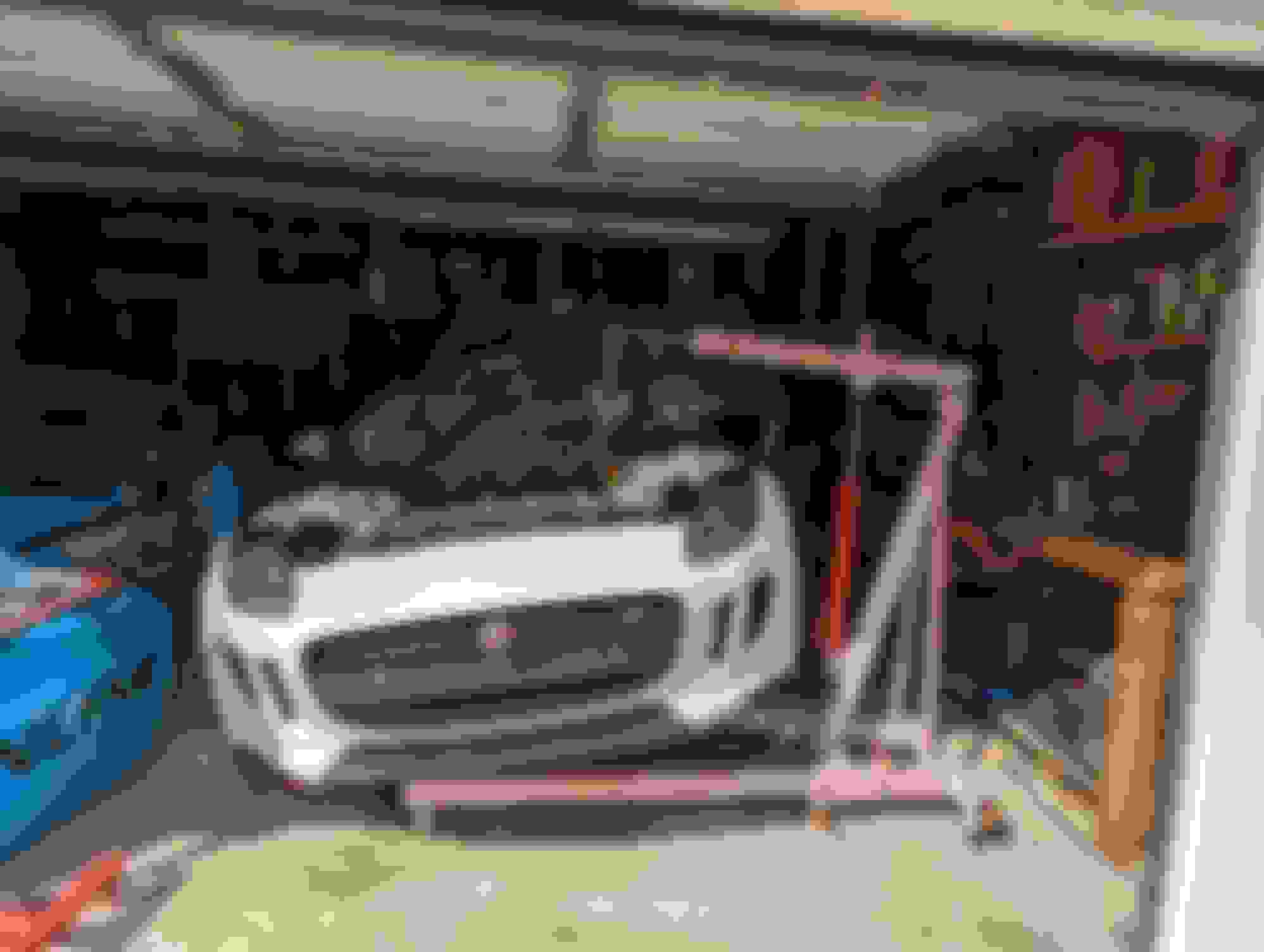
I first started soaking the injector in 50/50 ATF/Acetone mixture for 3 days, in parallel I'd make 20-30 hits every few hours for days with the JLR fuel injector removal tool (I welded a longer slide rod to the tool for a longer travel and used a 2lbs slide weight). After a thousand hits, I eventually went to the engine crane method, putting constant pull resistance on the injector for 3 days with the front wheel lifting. I'd occasionally added air hammer hits to the end of the tool, but it just wouldn't come out. I knew at that point I just had to remove the cylinder head and press the injector out from the combustion chamber side.
Special Tools needed: (If anyone ends up needing to do a similar job in the future, I'd be happy to lend the tools out for a small fee. I'm located in Houston, TX)
-Crankshaft Pulley Puller/Installer kit:
Parts needed (specific to the cylinder head removal only):
LH Headgasket: AJ813951 (Based on my research, you should only use the OEM HG, multiple people reported leakages with aftermarket OE replacement HG)
Head Bolts x8: AJ812892
Front Crank Seal: AJ811449
Crankshaft pulley bolt: AJ811490
VVT gasket kit: https://www.rkxtech.com/products/rkx...c58fd8b8&_ss=r
Valve Cover Gasket: https://euro-amp.com/products/2013-2...2d3526-c2d3527
Vacuum pump gaskets: https://www.rkxtech.com/collections/...-rr-superchrgd
Timing chain tensioners x2: AJ813898
If your timing chains and guides show wear or you're >=100K miles, then I would suggest to replace the chains/guides as well (mine were in excellent condition and didn't need to be changed)
What I've learned:
It's not a terrible job if you're mechanically inclined or have automotive repair experience. It only took a few hours to get the work done, but it took me along time waiting on special tools & parts.
There are a lot lots of special tools needed
This can be done with the ENGINE IN CAR.
You have to remove the Hood, Rad fan, x brace, coolant hoses, and belt pullies in front to make room and get to the timing covers
Exhaust manifold can be left on the head, just disconnected from the CAT
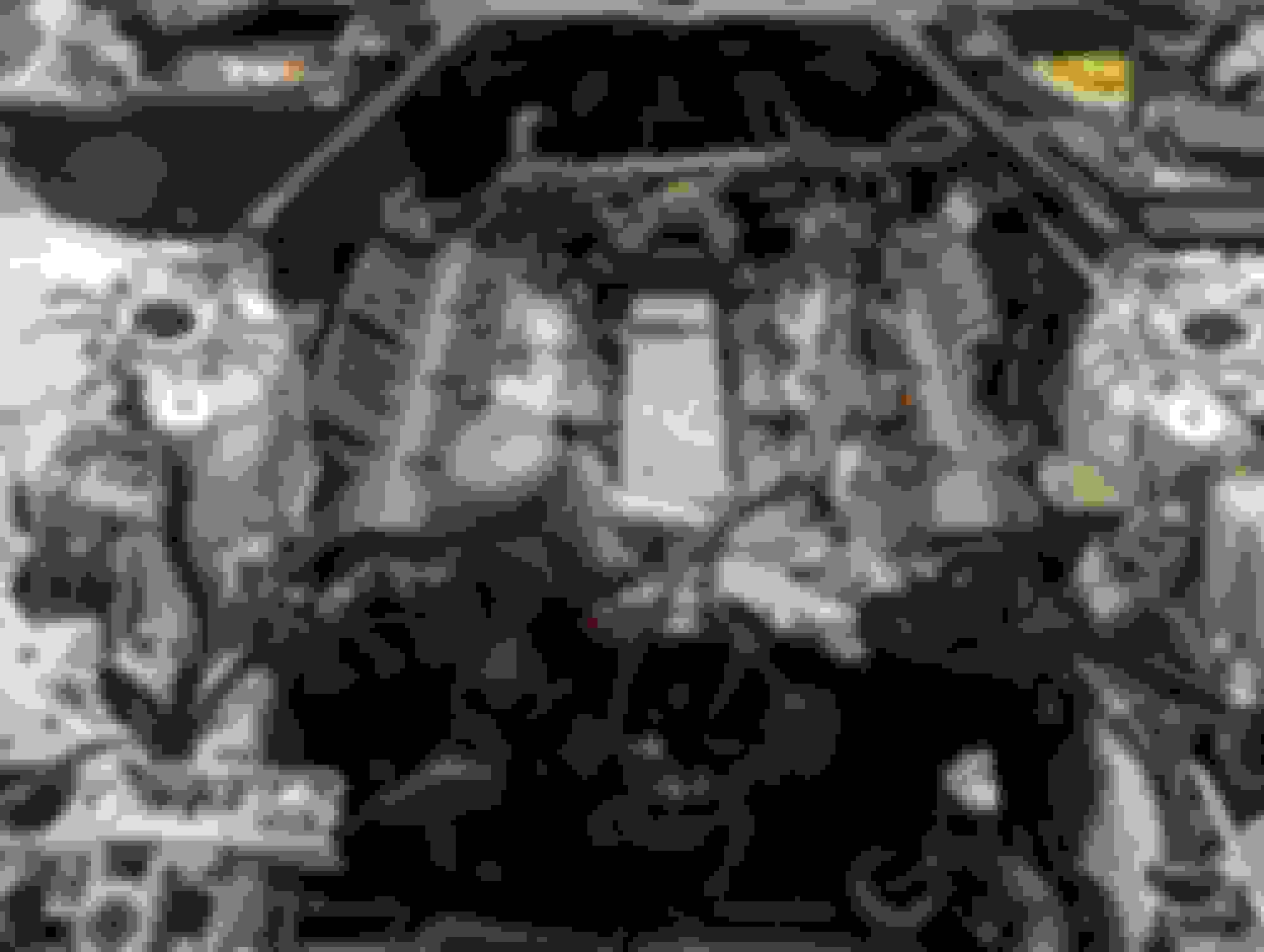
Process:
Removing peripherals
Remove the hood to give you enough space to work in front of the engine
Follow the Injector removal guide to depressurizing the fuel system and removing the negative battery cable from the Injector DIY guide. Make sure if you disconnect the battery that you put a glove or something to prevent the trunk from latching.
Drain coolant from the radiator drain
Remove the covers, ignition coils, fuel lines, and injectors
Refer to the S/C removal guide and remove the supercharger and accompanying bits
Remove s/c coolant hoses, upper radiator hose, water pump to tstat hose in front of the engine to give you more space to work with
Remove the rear plastic crossover coolant pipe
Remove the vacuum line from the vac pump
Remove the center cross brace (2-13mm bolts), X brace (4-13mm bolts), and radiator fan (has one 8mm bolt holding it on the RH side, the LH side has a clip you need to depress to lift it up and out)
Remove s/c belt, drive belts, belt tensioners, and idle pullies
Remove P/S pulley if you have hydro P/S - I suggest using a gear puller to avoid damaging the aluminum timing cover from prying
If you're removing the LH Cylinder head, you can remove the P/S pump as well (2 - 10mm bolts in front and 1 - 10mm bolt in the rear below the heat shield
Disconnect the CAT from the exhaust manifold & unplug the primary O2 sensor from the harness
Partially or fully drain the engine oil
Remove vacuum pump
Crank pulley removal:
Remove the starter cable heart shield, remove starter power and connector, remove starter, and install special timing tool to lock the flywheel
Follow instructions to install the crank pulley holder to undo the crank pulley bolt, it will require tremendous force to undo - I had to use a 3/4 drive breaker bar with a 4' 1.75x.095 steel tube; My crank pulley bolt was Left hand threaded (clockwise to loosen, counterclockwise to tighten)
Once you remove the crank pulley bolt, install the crank pulley puller tool and remove crank pulley
Lock engine timing:
Keep the starter ring gear holder tool in place
Install the crank pulley bolt back into the crank snout and snug it up so that you can withstand the force to rotate the engine clockwise
Remove the ring gear holder tool from the starter
Slowly rotate the crankshaft CLOCKWISE until the crank keyway is at the 6 oclock position
Remove the Crank position sensor and install the crank position locking pin
Reinstall the starter ring gear holder tool
Remove valve covers
Follow directions to install the cam locking tools on each bank
Your engine is now locked for timing, go ahead and remove the lower and upper timing covers
Timing system:
Remove the timing chain tensioner on the bank you're working to remove. The oil extraction tube will need to be unbolted to work around the chain/guides on the LH side.
Remove the active chain guide
Remove the passive chain guide (slack side)
Undo the 3 cam gear/VVT bolts and remove the timing chain
Be sure to handle the cam gears with care as they have plastic pads inside that can break if you drop the cam gear
Camshafts:
Remove the special tool locking the cams
Remove the cam caps - Unbolt the camshafts via the sequence indicated in the manual
Caps are labeled except for the front caps, I would mark them as they absolutely need to be reinstalled in the correct positions
Remove cams
Remove shim buckets - make note of their orientation as they will need to be reinstalled in the same positions - unless you plan on doing a valve clearance adjustment, then you'll be spec'ing each valve for proper clearance
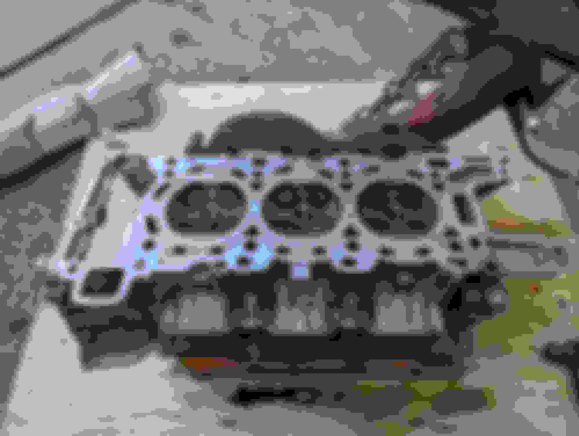
Head removal:
With the cams now out, you can access the head bolts
Using a 12MM RIBE socket, slowly loosen the head bolts a little at a time, evenly as indicated in the workshop manual's sequence - similar to the torque steps during assembly, my practice is the same when undoing the bolts to ensure we don't warp the head
Remove the 8 head bolts
Remove the 4 - 10mm bolts and 2 - T30 torx bolts at the timing chain case
Remove the knock sensor to avoid breaking
Since I didn't remove the exhaust manifold from the head, I had to maneuver the head to clear it out of the engine bay, but it's wasn't too bad
Head re-installation is just in reverse order with a few notable items.
-I used brand new head bolts and I used moly assembly lube to lube the threads. I did not see ANY mention in the workshop manual regarding lubricating the head bolts, but with that much torque on aluminum threads, it is a common best practice to lube them up so they do not bind while torqueing.
-There are 2 dowel pins that locate the head to the block, mine has some corrosion on them so i cleaned them up with some scotchbrite and put some anti seize on them to make removal easier in the future.
Re-time the engine:
-Follow the procedure in the workshop manual, it's well documented and easy to follow
-There is a special procedure to add tension to the cam gears using a special tool in the timing kit. Procedure is documented in the workshop manual as well, but don't skip this step.
-Once you think you have the engine all timed up, remove the cam locks, the starter ring gear holder, and crank position pin lock, rotate the engine clockwise for 2 full revolutions then re-install all the specialty timing locks - if you are not able to correctly install them, your engine may not have been timed correctly.
-In my case, my timing system components looked excellent with very minimal stretch or wear. Since we know timing chain tensioners are usually the weak point, I replaced the TCT but left the chain and guides alone.
Timing cover re-install:
-Since I was already there, I went ahead and replaced the VVT Actuator seals and Cam position sensor gaskets
-The upper covers just requires some RTV sealant to mate to the head
-I elected to replace the front crankshaft seal, which requires that special 3 prong tool to remove/install - but reused the lower timing cover
-If you reuse the lower timing cover, be sure to clean the mating surfaces well and apply RTV silicone to the lower cover
-Make sure to use the lower timing cover alignment tool upon installing the lower cover so that the crank doesn't burn up the seal, there is adjustability in the lower cover so you don't want to find oil leaks later
The rest of reassembly is just performed in reverse. Nothing caught me off guard and the workshop procedures are easy to follow along with torque steps & figures. I elected to apply a bit of anti-seize to the base of the injector where I saw corrosion (pics attached). I did not experience any leaks, but I suspect this may help with removal in the future. Same with the supercharger locating dowel pins.
Prior to firing up the engine, I filled with oil, primed the engine, did a compression test, and also pulled vacuum on the coolant system to check for leaks & perform a vacuum coolant fill. This car has an elaborate and complex coolant system with lots of lines, so vac filling is a good and practical practice.
Again, this wasn't meant to be comprehensive, but calling out few things that I was caught off by and having all the part numbers and special tools listed in one place for the next person. Hope this helps if you're in the same predicament!
WOW! What a superb job you did in outlining this procedure with not only parts and tools, but also the links to obtain them. I'm sure just writing this up took a few hours of your time. My hat off to you and many thanks. I hope I never have to do this, but it's people like you that give others encourgement to do their own work. Have you considered making videos? I'm sure they would sell !!
WOW! What a superb job you did in outlining this procedure with not only parts and tools, but also the links to obtain them. I'm sure just writing this up took a few hours of your time. My hat off to you and many thanks. I hope I never have to do this, but it's people like you that give others encourgement to do their own work. Have you considered making videos? I'm sure they would sell !!
Thank you for the positive feedback! As long as it helps someone else I'm satisfied. I never considered making vids just because of how much time and effort it takes to making the video meaningful and useful and that would detract from my actual wrenching.
Originally Posted by randyb
Great job and do you think the corrosion came from the hood vent draining water on it?
Yes, 100% came from the hood vents. I believe the anti-seize will prevent this moving forward, but I will be fabricating rain duct channels on the hood side to prevent corrosion in other places on the engine.
[QUOTE=Jp129;2657060]Time for me to return the favor and give back to the community in which I've been able to take valuable information and feedback from. This will not serve as a comprehensive DIY guide for the cylinder head removal process, but as centralized information and supplemental info to the Factory Workshop manual/ existing DIY's that cover things like S/C removal, ignition, Injectors, etc that need to be removed to get to the timing system or head removal.
The Tragedy:
A leaky valve cover gasket is what prompted me to do the usual overhaul maintenance on the F type (coolant pipes, S/C coupler, Injector service, gaskets, etc) but that was the basis to remove the injectors. Long story short, 5 of 6 injectors came out with very minimal effort, but the 6th proved to be the end of that dream. It was cylinder #4 injector that was completely seized, which is the first cylinder on the LH bank.
I first started soaking the injector in 50/50 ATF/Acetone mixture for 3 days, in parallel I'd make 20-30 hits every few hours for days with the JLR fuel injector removal tool (I welded a longer slide rod to the tool for a longer travel and used a 2lbs slide weight). After a thousand hits, I eventually went to the engine crane method, putting constant pull resistance on the injector for 3 days with the front wheel lifting. I'd occasionally added air hammer hits to the end of the tool, but it just wouldn't come out. I knew at that point I just had to remove the cylinder head and press the injector out from the combustion chamber side.
Special Tools needed: (If anyone ends up needing to do a similar job in the future, I'd be happy to lend the tools out for a small fee. I'm located in Houston, TX)
-Crankshaft Pulley Puller/Installer kit:
Parts needed (specific to the cylinder head removal only):
LH Headgasket: AJ813951 (Based on my research, you should only use the OEM HG, multiple people reported leakages with aftermarket OE replacement HG)
Head Bolts x8: AJ812892
Front Crank Seal: AJ811449
Crankshaft pulley bolt: AJ811490
VVT gasket kit: https://www.rkxtech.com/products/rkx...c58fd8b8&_ss=r
Valve Cover Gasket: https://euro-amp.com/products/2013-2...2d3526-c2d3527
Vacuum pump gaskets: https://www.rkxtech.com/collections/...-rr-superchrgd
Timing chain tensioners x2: AJ813898
If your timing chains and guides show wear or you're >=100K miles, then I would suggest to replace the chains/guides as well (mine were in excellent condition and didn't need to be changed)
What I've learned:
It's not a terrible job if you're mechanically inclined or have automotive repair experience. It only took a few hours to get the work done, but it took me along time waiting on special tools & parts.
There are a lot lots of special tools needed
This can be done with the ENGINE IN CAR.
You have to remove the Hood, Rad fan, x brace, coolant hoses, and belt pullies in front to make room and get to the timing covers
Exhaust manifold can be left on the head, just disconnected from the CAT
Process:
Removing peripherals
Remove the hood to give you enough space to work in front of the engine
Follow the Injector removal guide to depressurizing the fuel system and removing the negative battery cable from the Injector DIY guide. Make sure if you disconnect the battery that you put a glove or something to prevent the trunk from latching.
Drain coolant from the radiator drain
Remove the covers, ignition coils, fuel lines, and injectors
Refer to the S/C removal guide and remove the supercharger and accompanying bits
Remove s/c coolant hoses, upper radiator hose, water pump to tstat hose in front of the engine to give you more space to work with
Remove the rear plastic crossover coolant pipe
Remove the vacuum line from the vac pump
Remove the center cross brace (2-13mm bolts), X brace (4-13mm bolts), and radiator fan (has one 8mm bolt holding it on the RH side, the LH side has a clip you need to depress to lift it up and out)
Remove s/c belt, drive belts, belt tensioners, and idle pullies
Remove P/S pulley if you have hydro P/S - I suggest using a gear puller to avoid damaging the aluminum timing cover from prying
If you're removing the LH Cylinder head, you can remove the P/S pump as well (2 - 10mm bolts in front and 1 - 10mm bolt in the rear below the heat shield
Disconnect the CAT from the exhaust manifold & unplug the primary O2 sensor from the harness
Partially or fully drain the engine oil
Remove vacuum pump
Crank pulley removal:
Remove the starter cable heart shield, remove starter power and connector, remove starter, and install special timing tool to lock the flywheel
Follow instructions to install the crank pulley holder to undo the crank pulley bolt, it will require tremendous force to undo - I had to use a 3/4 drive breaker bar with a 4' 1.75x.095 steel tube; My crank pulley bolt was Left hand threaded (clockwise to loosen, counterclockwise to tighten)
Once you remove the crank pulley bolt, install the crank pulley puller tool and remove crank pulley
Lock engine timing:
Keep the starter ring gear holder tool in place
Install the crank pulley bolt back into the crank snout and snug it up so that you can withstand the force to rotate the engine clockwise
Remove the ring gear holder tool from the starter
Slowly rotate the crankshaft CLOCKWISE until the crank keyway is at the 6 oclock position
Remove the Crank position sensor and install the crank position locking pin
Reinstall the starter ring gear holder tool
Remove valve covers
Follow directions to install the cam locking tools on each bank
Your engine is now locked for timing, go ahead and remove the lower and upper timing covers
Timing system:
Remove the timing chain tensioner on the bank you're working to remove. The oil extraction tube will need to be unbolted to work around the chain/guides on the LH side.
Remove the active chain guide
Remove the passive chain guide (slack side)
Undo the 3 cam gear/VVT bolts and remove the timing chain
Be sure to handle the cam gears with care as they have plastic pads inside that can break if you drop the cam gear
Camshafts:
Remove the special tool locking the cams
Remove the cam caps - Unbolt the camshafts via the sequence indicated in the manual
Caps are labeled except for the front caps, I would mark them as they absolutely need to be reinstalled in the correct positions
Remove cams
Remove shim buckets - make note of their orientation as they will need to be reinstalled in the same positions - unless you plan on doing a valve clearance adjustment, then you'll be spec'ing each valve for proper clearance
Head removal:
With the cams now out, you can access the head bolts
Using a 12MM RIBE socket, slowly loosen the head bolts a little at a time, evenly as indicated in the workshop manual's sequence - similar to the torque steps during assembly, my practice is the same when undoing the bolts to ensure we don't warp the head
Remove the 8 head bolts
Remove the 4 - 10mm bolts and 2 - T30 torx bolts at the timing chain case
Remove the knock sensor to avoid breaking
Since I didn't remove the exhaust manifold from the head, I had to maneuver the head to clear it out of the engine bay, but it's wasn't too bad
Head re-installation is just in reverse order with a few notable items.
-I used brand new head bolts and I used moly assembly lube to lube the threads. I did not see ANY mention in the workshop manual regarding lubricating the head bolts, but with that much torque on aluminum threads, it is a common best practice to lube them up so they do not bind while torqueing.
-There are 2 dowel pins that locate the head to the block, mine has some corrosion on them so i cleaned them up with some scotchbrite and put some anti seize on them to make removal easier in the future.
Re-time the engine:
-Follow the procedure in the workshop manual, it's well documented and easy to follow
-There is a special procedure to add tension to the cam gears using a special tool in the timing kit. Procedure is documented in the workshop manual as well, but don't skip this step.
-Once you think you have the engine all timed up, remove the cam locks, the starter ring gear holder, and crank position pin lock, rotate the engine clockwise for 2 full revolutions then re-install all the specialty timing locks - if you are not able to correctly install them, your engine may not have been timed correctly.
-In my case, my timing system components looked excellent with very minimal stretch or wear. Since we know timing chain tensioners are usually the weak point, I replaced the TCT but left the chain and guides alone.
Timing cover re-install:
-Since I was already there, I went ahead and replaced the VVT Actuator seals and Cam position sensor gaskets
-The upper covers just requires some RTV sealant to mate to the head
-I elected to replace the front crankshaft seal, which requires that special 3 prong tool to remove/install - but reused the lower timing cover
-If you reuse the lower timing cover, be sure to clean the mating surfaces well and apply RTV silicone to the lower cover
-Make sure to use the lower timing cover alignment tool upon installing the lower cover so that the crank doesn't burn up the seal, there is adjustability in the lower cover so you don't want to find oil leaks later
The rest of reassembly is just performed in reverse. Nothing caught me off guard and the workshop procedures are easy to follow along with torque steps & figures. I elected to apply a bit of anti-seize to the base of the injector where I saw corrosion (pics attached). I did not experience any leaks, but I suspect this may help with removal in the future. Same with the supercharger locating dowel pins.
Prior to firing up the engine, I filled with oil, primed the engine, did a compression test, and also pulled vacuum on the coolant system to check for leaks & perform a vacuum coolant fill. This car has an elaborate and complex coolant system with lots of lines, so vac filling is a good and practical practice.
Again, this wasn't meant to be comprehensive, but calling out few things that I was caught off by and having all the part numbers and special tools listed in one place for the next person. Hope this helps if you're in the same predicament!
Do you still have the tools available for this job? What is the loaner fee?
Do you think you could have done it with the hood on?
I do not have a garage and the place where I live does not allow disassembled cars, even for an hour or two.
Also, how hard was it to remove the crankshaft bolt?
Why did you take off the VVT gears, looks like it would be simpler to leave them in place?
How did you punch out the injectors?
I left the hood on. I just took the strut supports off and used a punch to put them at "max" opening with one of the available holes on the pivot.
The crankshaft bolt is high torque. I had a thick walled 4' steel tube stock that I paired up with my 3/4" breaker as a "cheater cheater " bar so that made it fairly uneventful. If you don't have access to such a cheater bar or BMF impact torque wrench, I suspect it may be a struggle.
I can't say if leaving the VVT gears in place would've been easier since I decided it would be a good time to replace the tensioners, guide, and chain while everything was apart. That path made my choice for me. The service manual calls for the tensioning procedure of the VVT gears, so I suspect it best to remove and follow the procedure. Its the first time working on an AJ126, so I didn't have any other resource to fall on.
I punched out the one stuck injector with a punch. Used a punch that was smaller than the OD of the injector hole and be a as careful not to slip and hit the combustion chamber as possible. It only took 3 medium blows with my dead blow and it was out. I was lazy otherwise a press would've provided more controlled extraction.
I only had one stubborn injector, the others all popped out with the slide hammer extraction tool.
I know why jag mechanics don't want to take the heads off. Besides a million parts and instructions most surgeons would avoid, you have specialty tools and parts. I have (I sincerely hope) one last question, with the SC removed, can you just turn it over and drain the oil or do you still need a vacuum pump?
I know why jag mechanics don't want to take the heads off. Besides a million parts and instructions most surgeons would avoid, you have specialty tools and parts. I have (I sincerely hope) one last question, with the SC removed, can you just turn it over and drain the oil or do you still need a vacuum pump?
Yes, on the V6, the S/C oil fill is on the top side and there is no drain. Once you have the S/C removed from the engine, you can just flip it over and drain the oil. Since the oil fill volume is critical, I dumped the oil into a graduated cylinder and just replace what came out exactly.
Prior to this ordeal that forced an S/C removal, I used a syringe with a small gauge needle to extract the S/C oil when it was insitu and there wasn't much more that came out when I flipped it over. So for those that are just looking to do an oil change, it's not worth it to remove the S/C for an oil change to drain it "completely", IMO.
If your jag hasn't had the S/C coupler replaced, I also think this is a great time to do it since it's already out.

 07-03-2023 | 01:30 PM