
Power seat wiring to make it work Outside the car?

#62
 05-26-2017, 11:02 PM

Junior Member
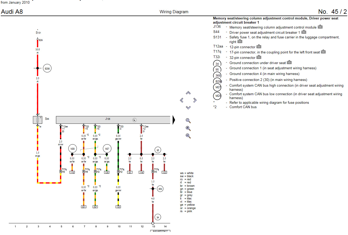
Finally I�ve found the wiring diagram for the A8 Seat, here is:
And here is the complete PDF with all the wiring information:
TinyUpload.com - best file hosting solution, with no limits, totaly free
And here is the complete PDF with all the wiring information:
TinyUpload.com - best file hosting solution, with no limits, totaly free
#63
03-31-2018, 01:24 PM

Junior Member
Join Date: Mar 2018
Location: Derby
Posts: 3
Likes: 0
Received 0 Likes
on
0 Posts
Wiring diagrams for the 2004 XJ to download here http://jaguar.bttlxe.com/xj/2004%20XJ.zip
New member here I was hoping to get a copy of the drawings mentioned in this post unfortunately the link is dead any chance you can help ,, fingers crossed and many thanks in advance
Ian
#64
05-17-2020, 08:54 PM

#65
05-18-2020, 05:40 AM
Veteran member
Join Date: May 2008
Location: Great Mills, MD
Posts: 14,452
Likes: 0
Received 3,929 Likes
on
3,225 Posts
James, what year car are we talking about here. I may have drawing for a newer car, I may not.
As for hardwiring the seat and bypassing all the modules, this can be done for the most part. With this being said, you wlil loose any memory function and the seat heaters will not have an auto off function unless you add that to your design (can be done with something as simple as a long time agastat. Let me know what you are after and we can take things from there.
As for hardwiring the seat and bypassing all the modules, this can be done for the most part. With this being said, you wlil loose any memory function and the seat heaters will not have an auto off function unless you add that to your design (can be done with something as simple as a long time agastat. Let me know what you are after and we can take things from there.
#67
05-18-2020, 04:16 PM
Veteran member
Join Date: May 2008
Location: Great Mills, MD
Posts: 14,452
Likes: 0
Received 3,929 Likes
on
3,225 Posts
James, I just happen to have the wiring diagram for the left seat. I think you can figure out how things go from there. What I would say to use is say a 7 AH 12 VDC battery to power the seat. You can then use a small say 500 mA 12 VDC charger to maintain the seat. When you operate the seat, the battery is going to supply the multiple amps needed to make the seat move. But, the charger will restore that power over time to keep the battery at 100%. Can probably even get away with only charging the battery for say an hour a week and be good unless you plan on moving the seat a lot. Look at the diagram I have attached. That should have all the wiring that you need to figure out how to make the seat move. Then all you need to find is say 5 or 6 momentary ON-OFF-ON switches. Then you can wire them up to do the up/down features with a single switch. If you need help with that, it is simple. Let me know and I will send you a little drawing to explain what you need to do.
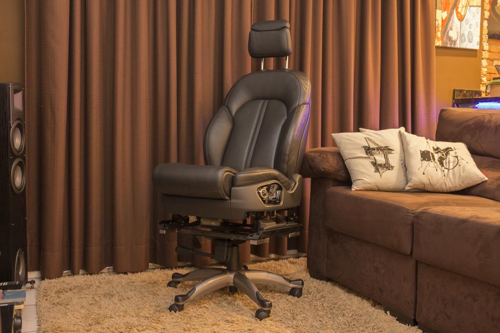
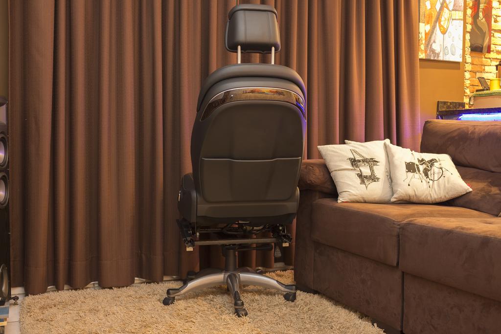
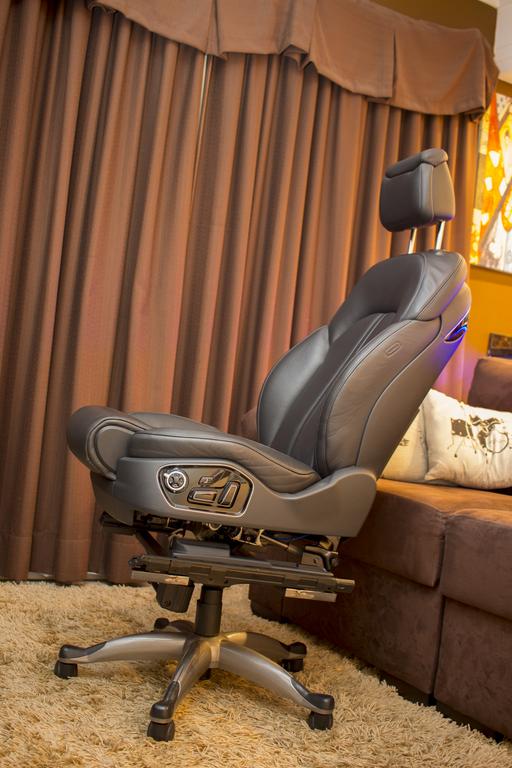
The more that I look at the Jaguar seat on a rolling base, the more I am tempted on building one. I have a welder, so, making the base would be cake and wiring it up would be pretty easy too. Besides, my computer chair is getting old and in need of an "update". LMAO.
The more that I look at the Jaguar seat on a rolling base, the more I am tempted on building one. I have a welder, so, making the base would be cake and wiring it up would be pretty easy too. Besides, my computer chair is getting old and in need of an "update". LMAO.
#68
05-19-2020, 04:39 AM
That�s absolutely brilliant. Thank you.
im guessing I can�t use the standard seat switches then, I�m fitting it into my Land Rover defender so powers won�t be a problem, I�ve managed to sort out the wiring to get them movement but it�s that bloody �inch mode� setting that�s tripping me up.
thanks
im guessing I can�t use the standard seat switches then, I�m fitting it into my Land Rover defender so powers won�t be a problem, I�ve managed to sort out the wiring to get them movement but it�s that bloody �inch mode� setting that�s tripping me up.
thanks
#69
05-19-2020, 05:34 AM
Veteran member
Join Date: May 2008
Location: Great Mills, MD
Posts: 14,452
Likes: 0
Received 3,929 Likes
on
3,225 Posts
#70
05-19-2020, 05:42 AM
I think the chip is in the seat module connected to the seat, my seat is the heated X250 model, it�s unbelievably more complicated than the passenger side. I�m wondering if I take apart the switch panel on the side of the seat, If I can rewire the switches to use them, I am sceptical of this
Last edited by James h; 05-19-2020 at 05:49 AM.
#71
05-19-2020, 10:30 AM
Veteran member
Join Date: May 2008
Location: Great Mills, MD
Posts: 14,452
Likes: 0
Received 3,929 Likes
on
3,225 Posts
#72
05-20-2020, 11:01 AM

Junior Member


#74
12-06-2020, 11:25 AM

I am working on converting a 2013 XJ passenger seat into a computer chair. The chair is 12-way w/ memory, 4-way lumbar, and heated/cooled.. My first question is will I be able to power the seat and utilize the switch pack or will I need to purchase some DPDT momentary switches? I was able to verify the motors work by feeding pos/neg 12V to each motor. Next, I was going to start cutting everything out and just wire the switch pack to each motor, but I don't think the switch pack can handle 12v @ 20+amps...? Any help is appreciated!! Btw this forum is AWESOME :]
Here is the wiring diagram I found from another post (Pg 166): http://www.jagrepair.com/images/Elec...20-%20X351.pdf
#75
12-06-2020, 12:47 PM
Veteran member
Join Date: May 2008
Location: Great Mills, MD
Posts: 14,452
Likes: 0
Received 3,929 Likes
on
3,225 Posts
Krompy, let me check my diagrams. Wiring it up should be fairly easy and still use the switch pack on the side. Of note, you will probably want to have handy a small 12V battery (say a 7.0 Ah capacity). Trying to wire up a 12V P/S that has the current ability all by itself would be bulky and expensive. Using a small say 1 amp/12V power supply, you can use that to keep the battery topped up and when the motors kick in and draw their 10+ amps, the battery makes up the difference.
#76
12-06-2020, 06:16 PM
Krompy, let me check my diagrams. Wiring it up should be fairly easy and still use the switch pack on the side. Of note, you will probably want to have handy a small 12V battery (say a 7.0 Ah capacity). Trying to wire up a 12V P/S that has the current ability all by itself would be bulky and expensive. Using a small say 1 amp/12V power supply, you can use that to keep the battery topped up and when the motors kick in and draw their 10+ amps, the battery makes up the difference.
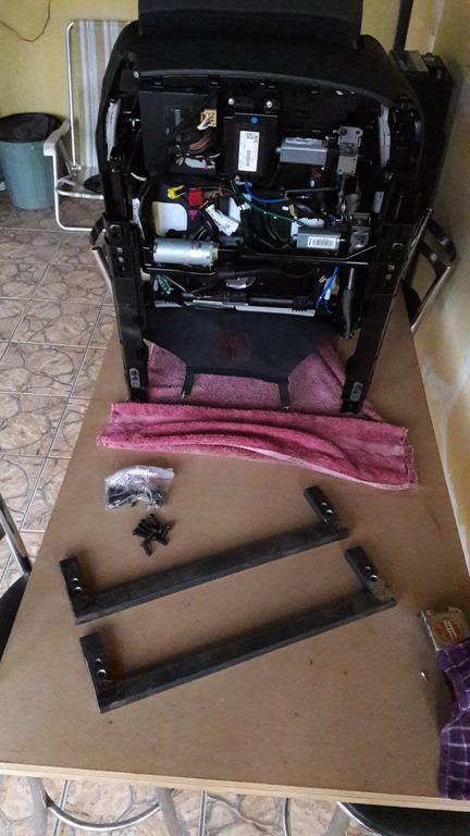
I will post pictures of what I am working with here shortly once I rewire the switch module to original state. Btw, I am planning to document this build and post to this forum for future reference to all. (I have scoured the internet the past week and haven't found anyone detailing the work-around to memory seats.)
Let me know if you need more information. THANK YOU
#77
12-06-2020, 06:31 PM
Veteran member
Join Date: May 2008
Location: Great Mills, MD
Posts: 14,452
Likes: 0
Received 3,929 Likes
on
3,225 Posts
Krompy, looking at the diagrams, the wiring up of the seat is pretty easy. Granted, do you have the plugs that go into the computers on the bottom of the seat. If not, that may be a good thing to get your hands on as this will make installation easier.
Lets start with the grounds. Looking, you are going to have 3 or 4 wires that you will need to find depending on how/where the harness was cut to separate the seat from the car. The good thing is all the wires are all black. 3 of the wires are going to be next to each other on the main computer of the seat. This should be a plug on the end of the computer that is a 14 pin plug. Pins 8, 10, and 11 should have black wires coming out of them. Now, depending on how the wires are cut, the black wire coming off of Pin 11 may be hard wired over to the switch pack already over to the black wire on the back side of the switch pack (See Pin 12 on the back of the switch pack). If this is the case, then you should have a spot where a wire taps off and you will simply need to connect that wire to the ones coming off of Pins 8 and 10. Tie all of these wires together and attach them to the negative post of the battery.
Now, for the power. The key marker for this is that all the wires are going to have a red stripe on them. So, the same plug that you found the 3 black wires, should have a yellow wire with a red stripe (Pin 6), a brown wire with a red stripe (Pin 12) and a blue wire with a red stripe (Pin 14). The wire on PIn 14 should be hardwired to the back of the switch pack and remain a blue wire with a red stripe and be attached to Pin 8 there. Combine all these wires into a common wire and attach them to the battery positive. Like with the ground, depending on how they cut the wiring under the seat when separating the car from the seat, the blue wire with a red stripe may or may not be intact.
At this point, you should be able to power the seat and it will perform all the normal functions of raising, lowering, leaning back/forward, etc. The only thing it will not be doing is running the heated seat. The heated seat aspect is a completely different monster.
If you have any more questions, let me know.
#78
12-11-2020, 01:51 PM
Krompy, looking at the diagrams, the wiring up of the seat is pretty easy. Granted, do you have the plugs that go into the computers on the bottom of the seat. If not, that may be a good thing to get your hands on as this will make installation easier.
Lets start with the grounds. Looking, you are going to have 3 or 4 wires that you will need to find depending on how/where the harness was cut to separate the seat from the car. The good thing is all the wires are all black. 3 of the wires are going to be next to each other on the main computer of the seat. This should be a plug on the end of the computer that is a 14 pin plug. Pins 8, 10, and 11 should have black wires coming out of them. Now, depending on how the wires are cut, the black wire coming off of Pin 11 may be hard wired over to the switch pack already over to the black wire on the back side of the switch pack (See Pin 12 on the back of the switch pack). If this is the case, then you should have a spot where a wire taps off and you will simply need to connect that wire to the ones coming off of Pins 8 and 10. Tie all of these wires together and attach them to the negative post of the battery.
Now, for the power. The key marker for this is that all the wires are going to have a red stripe on them. So, the same plug that you found the 3 black wires, should have a yellow wire with a red stripe (Pin 6), a brown wire with a red stripe (Pin 12) and a blue wire with a red stripe (Pin 14). The wire on PIn 14 should be hardwired to the back of the switch pack and remain a blue wire with a red stripe and be attached to Pin 8 there. Combine all these wires into a common wire and attach them to the battery positive. Like with the ground, depending on how they cut the wiring under the seat when separating the car from the seat, the blue wire with a red stripe may or may not be intact.
At this point, you should be able to power the seat and it will perform all the normal functions of raising, lowering, leaning back/forward, etc. The only thing it will not be doing is running the heated seat. The heated seat aspect is a completely different monster.
If you have any more questions, let me know.
Lets start with the grounds. Looking, you are going to have 3 or 4 wires that you will need to find depending on how/where the harness was cut to separate the seat from the car. The good thing is all the wires are all black. 3 of the wires are going to be next to each other on the main computer of the seat. This should be a plug on the end of the computer that is a 14 pin plug. Pins 8, 10, and 11 should have black wires coming out of them. Now, depending on how the wires are cut, the black wire coming off of Pin 11 may be hard wired over to the switch pack already over to the black wire on the back side of the switch pack (See Pin 12 on the back of the switch pack). If this is the case, then you should have a spot where a wire taps off and you will simply need to connect that wire to the ones coming off of Pins 8 and 10. Tie all of these wires together and attach them to the negative post of the battery.
Now, for the power. The key marker for this is that all the wires are going to have a red stripe on them. So, the same plug that you found the 3 black wires, should have a yellow wire with a red stripe (Pin 6), a brown wire with a red stripe (Pin 12) and a blue wire with a red stripe (Pin 14). The wire on PIn 14 should be hardwired to the back of the switch pack and remain a blue wire with a red stripe and be attached to Pin 8 there. Combine all these wires into a common wire and attach them to the battery positive. Like with the ground, depending on how they cut the wiring under the seat when separating the car from the seat, the blue wire with a red stripe may or may not be intact.
At this point, you should be able to power the seat and it will perform all the normal functions of raising, lowering, leaning back/forward, etc. The only thing it will not be doing is running the heated seat. The heated seat aspect is a completely different monster.
If you have any more questions, let me know.
Also, is it possible to fix the inch mode issue?
#79
12-11-2020, 03:30 PM
Veteran member
Join Date: May 2008
Location: Great Mills, MD
Posts: 14,452
Likes: 0
Received 3,929 Likes
on
3,225 Posts
Krompy, you can try using the battery that you have mounted to the seat, but I think you are going to find that you are only going to get about 15 minutes of heat out of the battery before the seat will turn itself off. I would recommend using something like this: https://www.ebay.com/itm/1Pc-12V-DC-...Cclp%3A2334524. That should allow you to power up the seat and supply power to the heater mechanism. The unit I reference is good for up to 30 amps and should be good enough to handle the chair.
#80
12-24-2020, 10:13 AM
Thermo, So I am about to order the timer you had suggested, but I am unsure how to power it. Can I feed 110Vac to it and it will output 12Vdc? I am guessing no... I think what you were suggesting is to use a 12V battery to power the seat and then wire this timer between it and the heater mech. However, like you said wouldn't the heater still drain the battery if I used for 10+ min?
2nd question: Can you suggest a 12v battery (7+ah) that is safe to mount with the chair (any orientation, no off-gases, Li-ion or lead acid?) and a trickle charger (smart charger?).
Happy Holidays !
2nd question: Can you suggest a 12v battery (7+ah) that is safe to mount with the chair (any orientation, no off-gases, Li-ion or lead acid?) and a trickle charger (smart charger?).
Happy Holidays !