When you click on links to various merchants on this site and make a purchase, this can result in this site earning a commission. Affiliate programs and affiliations include, but are not limited to, the eBay Partner Network.
Krompy, most of the timers that I am used to merely transfer power straight through them, pulling a small amount of power off to run the timer. So, no, a timer is not going to convert 110VAC to 12 VDC to power the seat.
Both of these batteries are going to do what you are after for the seat movement and will probably power up the seat heater for 5 minutes or so. Getting out to 10 minutes is going to pretty much kill the battery power wise.
Here is a timer that you may want to consider. It might be a little on the light side to power both seat and back heaters at the same time, but if you use only one, then you should be good. This also has a generic drawing of how it would get wired up. The load would be the seat wiring and the DC power would be from the battery. This unit is good for up to 10 amps. Worse case, you could use this to be your timer and then use a separate relay to power the seat. The switch side of the relay would be powered up to the load and then you would have the power side of the relay wired from the battery, through the relay, to the seat. That would allow you to draw as much power as you wanted.
Thank you Thermo for all the help!! Now, I have been trying to determine a good controller for the seats climate system. I purchased a DPDT switch that allows me to switch the TED units to either heating or cooling. However, this only allows me to run the system at 100%, which gives me no control of the output.. So, I was thinking about purchasing some sort of controller, but are $$$. I know if I limit the voltage to the fan via potentiometer then it would reduce the flow. However, this might damage the TED unit if the flow is too low. I think I need to control both the TED and the fan. Ideally, I'd like a controller that I can turn On/Off, switch heat or cool, and vary the temperature.
I thought about maybe going back to the junk yard and pulling out a HVAC climate controller from a car, but I am not sure if I can wire my 12v system to it or if it would require relays. Here is an example of what I talking about:
Krompy, the controller that you reference is not going to do what you are after. Those controllers really don't control the heat the way that you think. Atleast for the heat portion of the seat, what you are after is something more like: https://www.ebay.com/itm/DC6-60V-12V...Cclp%3A2334524
The push button turns it on, the dial allows you to control the heat from 0-100% through pulse width modulation (PWM). Easiest way to think of PWM is to think about having a high pressure source feeding through a needle valve to the input of a relief valve (which then vents to the atmosphere. If you just crack the needle valve, only a small mount of the source pressure makes it past the needle valve, but it will eventually reach a point that the relief valve will open up and quickly relieve the pressure. (this would be a very low percent on the dial. So, the amount of time that the relief valve is open compared to its shut time is small. So, very little energy gets released. Now, as you open the needle valve, more pressure can get by the needle valve and the relief valve will start to open more and more often. You can reach a point where the needle valve can be opened up far enough that the relief valve will just remain open (this would be 100% on the controller). Obviously, the more the system is allowed to relieve the pressure, the more work it can do. In this case, the more the controller is turned on, the more hot/cold it is going to make.
Now, how to control the hot/cold. This is more simple than you can imagine. Inside the seat is a peltier unit. This is a fancy heater in that it creates a hot and cold side when power is applied. If you had a peltier unit sitting on your desk, if you applied power to it and say the positive was on the left wire and the ground was on the right, then the peltier unit would have a hot top and a cold bottom. Now, if you reverse the wires (putting the ground on the left wire, positive on the right), then the unit would have a cold top and a hot bottom. So, to control whether the seat is hot or cold, you would simply use a 20 amp switch that is a double pole, double throw switch. The terminals on one end would have the wires coming in from the controller, the terminals in the center would be going to the seat and the terminals on the other end would be wired to the other terminals on the other side, just crossed to reverse the polarity. So, flipping the switch down would say turn on the heat, flipping the switch to the center would turn it off, and flipping the switch up would be cooling. If you use a triple pole, double throw switch, then you can wire up the seat blower to turn on when you have the power applied to the seat. if you need me to draw it out, let me know. I think you are going to find this much easier to wire up than you think.
Now, the only limitation with this set up is that you are not going to have protection from the seat getting too warm. But, this is where I am assuming that you are going to be sitting in the seat and when it starts to get too warm, you are going to either dial the unit down or turn it off.
Thermo, can I use the PWM controller to control both the fan speed and the peltier unit? Like if I wired the PWM controller output terminals to both the fan input and the peltier input and say I dialed the PWM down to 50%, would that slow the fan down to 50% speed as well as reduce the heat/ cooling from the peltier unit to 50%? - Or would this require I purchase two PWM controllers, one to regulate the fan speed and one for the peltier unit?
Krompy, you can use the one controller to power the fan and the peltier unit. I would tell you to wire the fan upstream of the switch and leave the peltier unit downstream of the switch. The seat doesn't power on the fan with the heat. It only turns on the fan for cooling. hence why I was saying to wire the fan up to the 3 pole switch. This would cause the fan to run at 100% regardless of the peltier unit setting. I am thinking a drawing will help clear up any confusion that we are having.
Krompy, take a look at this pic. I think this will make a lot more sense in how things need to be wired up. Pretty much, all the wiring is going to need to be say 14 or 12 gauge wiring to handle the 20ish amps that I see this pulling. the only exception will be the wiringto the seat fan. This can be 18 gauge wire as the fan pulls very little power. Kinda like all the switches that I am talking about will need to be rated for 20 amps (whether for 12, 24, or 120 volts, does not matter).
Thermo,
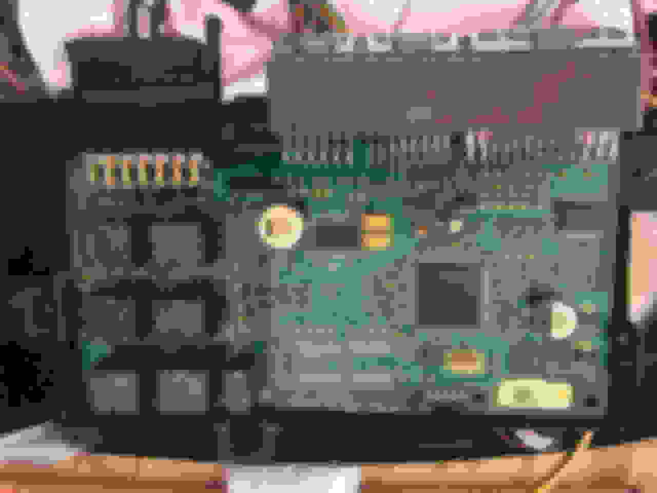
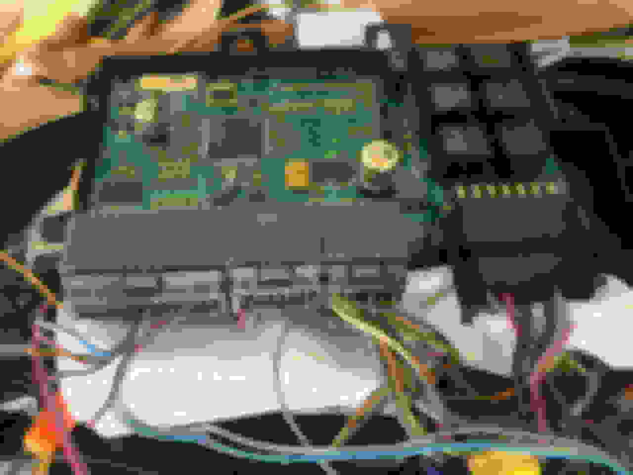
I cannot figure out to solve the "inch mode" issue when powering the seat i.e. the motors actuate for 0.5 second then stop. I have to actuate the motor switches multiple times in order to obtain position I want. I have done countless hours of searching the internet looking for a solution. This issue seems to be quite common... I believe the issue has something to do with the vehicle can bus requiring communication with the seat memory module. I am only using the seat as a work/gaming chair and do not have the vehicle can bus.
Do you know if I can trick the module by powering something so that the motors work properly? Maybe there is a wire for key ignition that needs to be fed power? Background: I cut most of the sensor wires going to each motor. I do not think these are needed in my case since I am not using the memory functionality. Reference below pics.
Thanks for all your help so far. I wired up a PWM to the climate system and everything works great! I am soo close to completing my dream chair :]
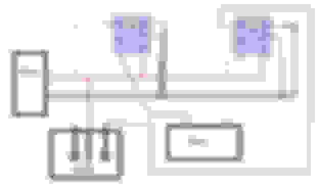
Krompy, unfortunately, I am not aware of any way to override the CAN Bus issue. The only solution that I can provide to you is to get rid of that circuit card and then what you are going to end up doing is wiring up a bank of relays (appears you will need 6 as that is what is on the circuit board that you have. In short, you are going to have a pair of relays working together to make a portion of the seat move. Below is a picture that I have drawn up that shows how it should be wired. The trick will be figuring out if the switches put a ground on the wire that is selected or if it puts power on the wire. I drew the picture with the assumption that it has power applied. There shouldn't be anything that you need to change wiring wise if it is the other way around. With this setup as I have drawn it, as long as you hold the button, there will be power applied to the motor. The thought process on how this works is that both sides of the motor are grounded at all times. Only when you attempt to move the seat is this not the case. As you position the switch, it causes a relay to pick up and switch the one wire from being grounded to having power applied. This allows the motor to then have a complete circuit and be able to move. You may need to play with the two motor wires and reverse them if you find that you have the switches backwards (ie, you go to tilt the seat forward, but it really goes backwards). But, that is an easy swap to make things function in the correct direction.
You will have to create a few of these circuits as you will need one for each motor in the seat. So, you will need one for the tilt of the seat, moving the seat front/back, raise/lower front of the seat, and raise/lower back of the seat.
Hi Thermo - you appear to be the seat wiring Guru!! I have a pair of RR Velar seats (marked up as Jag parts) - if I sent a pic of the underside would you be able to help identify which are the +ve and -ve to just drive the eat motors?
I know its a cheeky request - but my mum always said "if you don't ask in life you don't get"
KevC, I am going to send you a private message with my personal e-mail address. If you can tell me the year of vehicle it came from, i can probably give you a list of wires to put together to make the seat come alive. Odds are, you are going to be putting like 3 ground wires and 4-5 power wires to get the seat to respond. Take the advice of the previous posts. That will make installation very easy and minimize the amount of wiring you have going from your seat to the wall.
Hi there Thermo,
I�ve heard you are the main man here that can help me with my project. I need to get a set of front Range Rover l405 from 2014 seats working standalone from a donor car(i don�t have).
Reading this thread I have noticed that krompy�s seat he was using looks to have
similar controles but is one year older.
Any chance you could help me out?
I was originally planning on making a whole relay panel and ditching all the factory wiring. Also soldering on the back of the controle panel to reuse the original switches.
But with any luck that might not be necessary!!
Already wishing everyone here a merry Christmas!
Elliot
ElliotM, from the looks of things, you need to supply 12 VDC to the 2 large wires on the left most connector that are not black and the black wire is going to get the ground. That should power up most of the seat using the side controls. NOt sure what the tan wire may be for. I am thinking that it may also need to be connected in with the 2 large wires going to the positive power. But, without a drawing of the seat wiring, I am making an assumption. MOst of the wiring for the seat uses the black wires as ground and the colored wires are gonig to have a red stripe on them indicating that they are the positive wires. You have 2 positive wireis so you have 1 that has constant 12 VDC (from the battery) and then a switch 12 VDC (from the ignition switch) on the other. Since you are looking to do this for an office chair, having the 2 sources of power does not matter. So, you can wire them together.
Thanks for the fast response! I have given your suggestion a shot but with no succes. I have also tried both seats as I was thinking the salvage yard might have fried one apon removal(since the seats have to be moved to access the bolts holding it in place).
Apon connecting them like you suggested I had gotten zero response. Not a click or anything.
Would this not working maybe have something to do with the fact that there is a memory keypad in the door on the actual car?
let me know if more detailed photos of the seat and the wiring would help!
Elliot, if you have a diagram of the seats, then that would be very helpful to me. I can then tell you all the wires that you need to tap into. The memory keypad really should not affect anything. I will send you my e-mail addy if you have the drawings.
James, what year car are we talking about here. I may have drawing for a newer car, I may not.
As for hardwiring the seat and bypassing all the modules, this can be done for the most part. With this being said, you wlil loose any memory function and the seat heaters will not have an auto off function unless you add that to your design (can be done with something as simple as a long time agastat. Let me know what you are after and we can take things from there.
Hello sir i see a lot if post from you here, about X-Type power seat memory, me need the same thing, to power on the driver power seat with memory on a X-Type with electric seat, but without memory...Please can you help me? I'm going crazy... a lot of time wasted and no results 🥺🥺🥺
Costantino, if you look at the underside of the seat, you should see a large plug with 10 pins. This is your main power plug. Both the driver's and passenger's seats are wired the same except for 1 wire. This wire is for the door ajar and can affect how the seat moves. So, before you get into this too far, you need to know if you have a driver's seat or a passenger's seat. If you have both seats, then the one with less wiring on the underside is your passenger seat.
Now, for getting the seat to power up, you are going to need to supply power to 6 points. I mentioned the large plug with 10 terminals. If you look inside this plug, down at the base of the metal pins, you should see small numbers in the plastic going from 1 to 10. HOpefully whoever you got the seat from simply cut the wires and you still have both halves of the plugs as this will make things easier to wire up. But, you need to wire things as I state below: (please note, I am listing 2 wires for some points, the first one I list is for the passenger seat, the second is for the driver's seat).
Positive wire:
Pin 1 (orange wire w/ yellow stripe or orange wire w/ green stripe)
Pin 4 (white wire w/ blue stripe or green wire w/black stripe)
Pin 6 (green wire w/ black stripe for both)
Negative wire:
Pin 3 (Black wire for both)
Pin 5 (black wire for both)
Pin 10 (Black wire for both)
So, to make the seat move, you will wire the 3 positive points to a common power point and the 3 negative points to a common ground (negative) point. Now, if you are using the driver's seat, you need to find a large plug (will have a minimum of 22 pins in it. The wire on pin 22 is going to be a red wire. This will need to be tied to the ground wires. Without this wire tied to ground, you may find that the movement of the seat will be restricted to only a few functions.
On a side note, if you want heated seats, this is easy to wire up. All of the next wires are going to go from the points listed, through the device I state, then to the ground (negative) point. To turn the seat heater on, you will run a wire from Pin 2 (where you connected all the power wires) to a momentary on push button (only needs to be rated to handle 1 amp minimum) and then to the ground point. Tapping this button will turn on the seat on max heat, tapping it again would turn it on to low heat, and tapping it a third time would turn it off. The second wire will go from Pin 8 (where all the power wires are) to the positive lead of an LED (longer lead of the two) and then the shorter lead tied to the negative (ground) point. The same thing with Pin 9 as you did with Pin 8. These 2 LEDs are telling you what the seat heat level is. Both on, max heat, 1 on, low heat, both off, no heat. This may be getting into the seat a little more than you are after, but it is an option.
Now, all of this assumes you have the module in the bottom of the seat and you have not hacked the wiring harness to pieces. If you don't have the control module or the wiring harness has had numerous cuts made to it, then let me know. This is going to make wiring this up a bit more difficult as now we are going to have to replace all the relays inside the module with actual switches and this can be a very interesting project.
I posted a while back, thanks to everyone�s help i was able to get my jaguar seats working in my 55 bel air, but they are in I guess what you guys are calling �inch mode� is there a fix to this?
Hi,I have the same seats to fit in my 1973 V8 Rover do you have the wiring diagram for wiring up to the battery-regards Roger
Hi Chris
thank you for your reply-that will be most helpful,but I only have the part of the connector that is with the seat ,but I have emailed the breakers yard to see if they still have the other half of the plug with some cable attached
 12-25-2020, 09:03 AM