
HowTo: AJ34 Adjustable fuel pressure
#1
 07-29-2013, 09:43 PM

I installed a twin screw kit on my 4.2L XKR a few months ago and Avos and I have been banging our heads against a lean problem ever since, trying everything under the sun.
Frustrated with the inability to adjust the fuel pressure on the AJ34 single ended fuel system, I decided to dig in and see if there was a way to up the pressure and it turns out that there is.
Best of all it is simple and costs about $10 to build your own electronically adjustable fuel pressure regulator.
There is a full write up attached, but the highlights are that you need to intercept the signal from the fuel pressure sensor and bias it to a lower voltage, effective convincing the ECU that it needs to run the fuel pump a little faster. In this way, you can set the pressure to anything between the stock 55psi, up to about 70psi.
The circuit and how it is attached looks like:

I've got about 300 miles on the prototype without any problems. In the end, I will remake it in smaller form and with soldered, weather proof connections but my prototype installation for testing looks like:

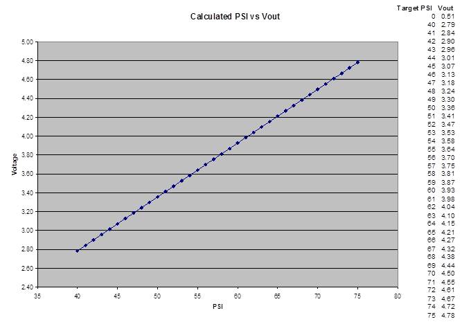
After collecting some data at different fuel pressures this is the linear fit to the Voltage-Pressure relationship for the pressure sensor:

Full write up:
AJ34_adjustable_fuel_pressure_r01.pdf
Frustrated with the inability to adjust the fuel pressure on the AJ34 single ended fuel system, I decided to dig in and see if there was a way to up the pressure and it turns out that there is.
Best of all it is simple and costs about $10 to build your own electronically adjustable fuel pressure regulator.
There is a full write up attached, but the highlights are that you need to intercept the signal from the fuel pressure sensor and bias it to a lower voltage, effective convincing the ECU that it needs to run the fuel pump a little faster. In this way, you can set the pressure to anything between the stock 55psi, up to about 70psi.
The circuit and how it is attached looks like:

I've got about 300 miles on the prototype without any problems. In the end, I will remake it in smaller form and with soldered, weather proof connections but my prototype installation for testing looks like:

After collecting some data at different fuel pressures this is the linear fit to the Voltage-Pressure relationship for the pressure sensor:
Full write up:
AJ34_adjustable_fuel_pressure_r01.pdf
The following 3 users liked this post by ccfulton:
#2
07-30-2013, 12:01 PM
Veteran Member
#3
08-17-2013, 11:14 PM
With the higher pressure it seemed as though it was falling off a bit at wide open throttle so I installed a Boost-a-Pump. It is mounted to the bracket that holds the CD changer / Nav DVD. Per the advice from Kenne Bell the BAP is connected on the voltage input to the pump driver.

I also added a couple of test points at the output from the BAP and the power feed to the pump. I shorted pressure switch wires so that the BAP would always output the increased voltage and mounted the adjustment near the BAP in the boot.

I was able to confirm that the output from the pump driver would change when adjusting the input voltage. After a short time, the pump driver would slow down the pump again to set the original pressure. At idle, with the 65psi setting, the pump is being driven with about 5.2V. This was measured with a DMM so it's the average voltage the pump sees, basically the Duty Cycle in % x the available voltage.
What the BAP does in this application is give the pump driver access to a higher voltage so that it doesn't need as much duty cycle to get the same flow output. This decreases the risk of running out of pump duty cycle range when the injector flow is at its highest.
With the engine running I saw 14.3V, so added 1V to that and set the BAP to output 15.3. I'll run that for a while and see how it performs.
I also noticed that the resistance of the pot shifted some with temperature. After a little investigation I found that the cheap one from Fry's had a pretty big resistance-temperature effect so I found a higher quality one form Digikey.
Ended up with a Vishay model: Y505110K0000J0L for $20.
Packaged this one a little more permanently and covered it in potting compound to make it weatherproof. The little box is actually from dental floss.

#5
08-20-2013, 03:33 PM
Veteran Member
#6
08-23-2013, 10:29 PM
Generally speaking I am game to make a few, but selling something comes with an implied expectation that it works and I haven't used it long enough yet to be 100% convinced that there isn't some unforeseen consequence.
#7
08-23-2013, 10:37 PM
The BAP is connected to the voltage source side of the PWM pump driver so the notion of a voltage drop is somewhat less than strait forward. In what way are you meaning when you say voltage drop?
The 5.2V I measure is between the two connections to the pump. I don't have a way to know what the actual PWM duty cycle is, so I can only infer it from the ratio of the input and output voltage assuming no loss in the driver circuit.
The 5.2V I measure is between the two connections to the pump. I don't have a way to know what the actual PWM duty cycle is, so I can only infer it from the ratio of the input and output voltage assuming no loss in the driver circuit.
Trending Topics
#8
08-23-2013, 10:49 PM
Veteran Member
Yes, on a PWM system circuit measuring voltage drop is awkward,
Instead you can infer the voltage drop by reference to standard charts relating current draw to wire gauge.
The point is that the fuel pump wiring used by OEM's is sometimes not adequate.
The first thing that tuners of other makes look at when addressing fuel pump delivery is the pump wiring on both the power and ground sides. The usual solution is to upgrade to #12 AWG on both sides. This is to ensure that the pump gets all the current it can from the available power. It can make a big difference.
On a PWM system, it would mean that the duty cycle is less at most times, and when at 100 percent, the pump will have more available current.
What the BAP partially does in effect is to up the voltage and in doing so, overcome any problems caused by undersized wiring.
#9
08-23-2013, 11:22 PM
Being lazy, I used Wire Resistance and Voltage Drop Calculator to calculate the voltage drop.
I had measured the full loop resistance of the circuit, including the pump, and got about 2 ohms. The total length of wire is maybe 4ft, from the pump driver to the pump.
I'd have to go back and check, but I think the pump wiring is #14, so not too small. The voltage loss should be about 1% for that case.
But like you say, the purpose of the BAP is to up the voltage and reduce the current for the same power output.
#10
09-20-2013, 04:41 PM
Thought I would add a follow up about this to the public record.
I've run 65psi fuel pressure for a while now and have noted some side effects worth mentioning.
After some run time, usually on a very hot day or when slogging around town, the indicated pressure rises about 5psi above the set point and then vary from 60 indicated, down into the 40s when accelerating and decelerating.
I think what is going on is that the pump driver is getting too hot and gets stuck on some fixed output mode, perhaps some kind of failsafe. It is quite hot to the touch and I know that 65 psi is near the max that the pump can provide at higher boost levels so it is working pretty hard. Even with the boost-a-pump the total power it's delivering will be the same.
Interestingly, this doesn't seem to happen when moving down the freeway, so I wonder if there is enough air moving through the boot to keep the pump driver cool enough it doesn't freak out.
So, in conclusion: the fuel pressure hack works, but be careful with it. Who knows what it might do to the longevity of your pump driver.
For myself, I'm pursuing some options to remedy my lean condition in other ways so I can set the pressure back to stock-ish levels.

Thread
Thread Starter
Forum
Replies
Last Post
Currently Active Users Viewing This Thread: 1 (0 members and 1 guests)