When you click on links to various merchants on this site and make a purchase, this can result in this site earning a commission. Affiliate programs and affiliations include, but are not limited to, the eBay Partner Network.
Doug,
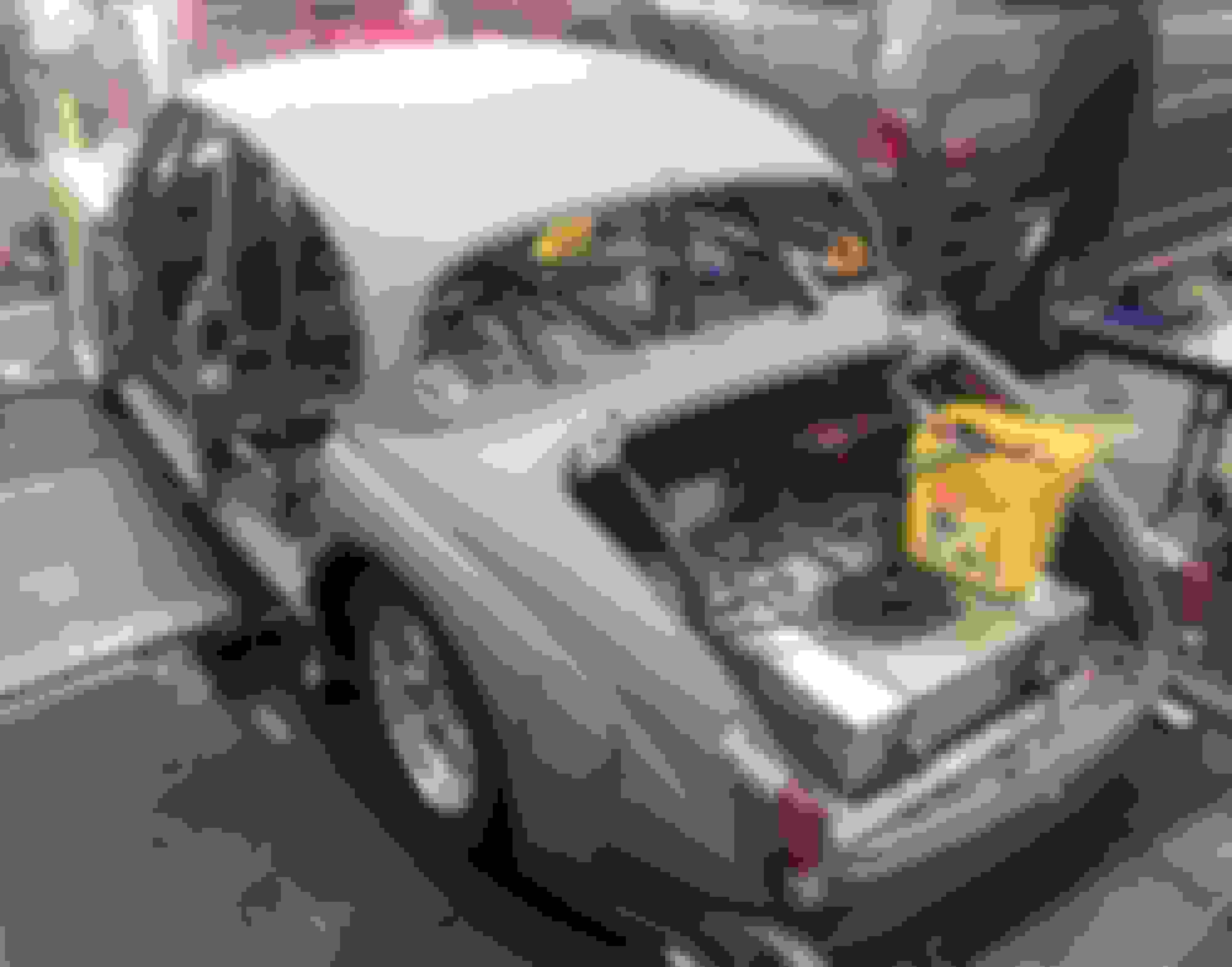
Thanks for the additional nudge. The on the ground pictures were taken November 2015, yikes. Got a phone call from the glass blaster about two weeks ago, wondering if I still had the rotisserie. I had to sheepishly reply that the MK2 was still on the "spit". I want to complete about 5-7 holes in the firewall, lay more wire in its final direction, make a final assessment of the underside, and put it on the ground again. If I really "turn to', this should happen shortly.
Cheers November 2015
Hmmmm, now that picture has given me some inspiration. Keep the wiring/fuses/relays away from under the bonnet for an ultra tidy engine bay. What a great idea, thanks!
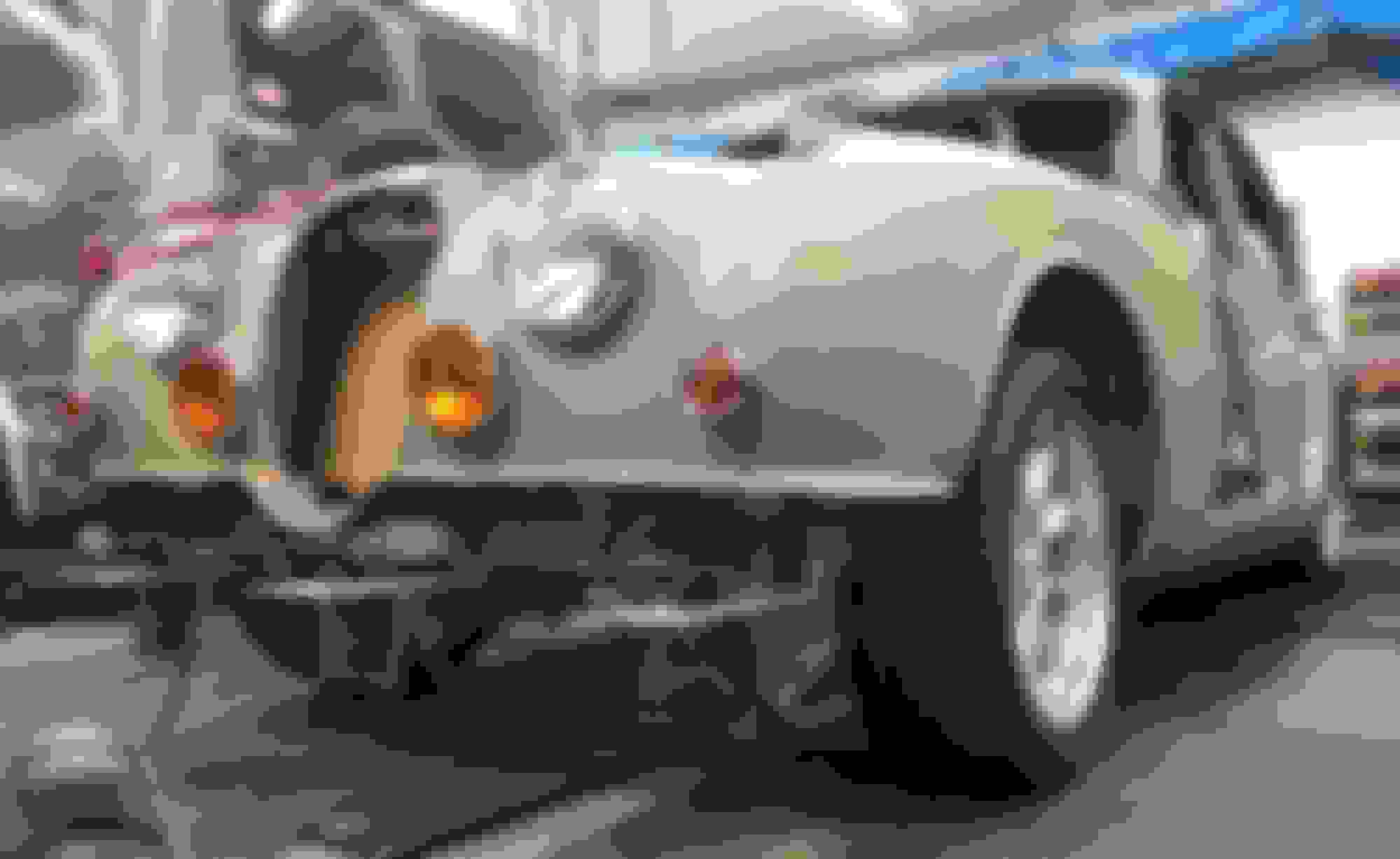
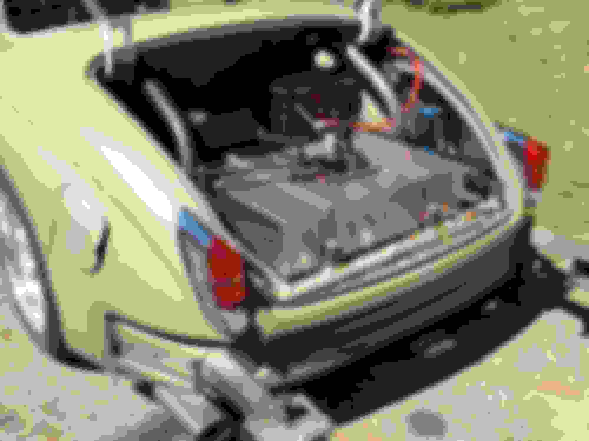
Well after five years on "the spit" (as my brother-in-law calls it), I set it back on the ground tonight. Shocks are set at minimal load. Ground clearance is better than expected - 5 1/2" in the rear. Wiring is laid in, not connected. I'll be dropping the engine in next week.
Thanks for looking.
Cheer
Congrats on touch down, Clyde - the wheel/tire combination should look perfect at ride height. Do you plan to finish the rear wheel openings, and what was the final decision for bonnet clearance?
Is that a rotisserie bracket at the rear or a Wheel-E-Bar mount? All the best with the project - can't wait to see some video of this thing launching.
Doug,
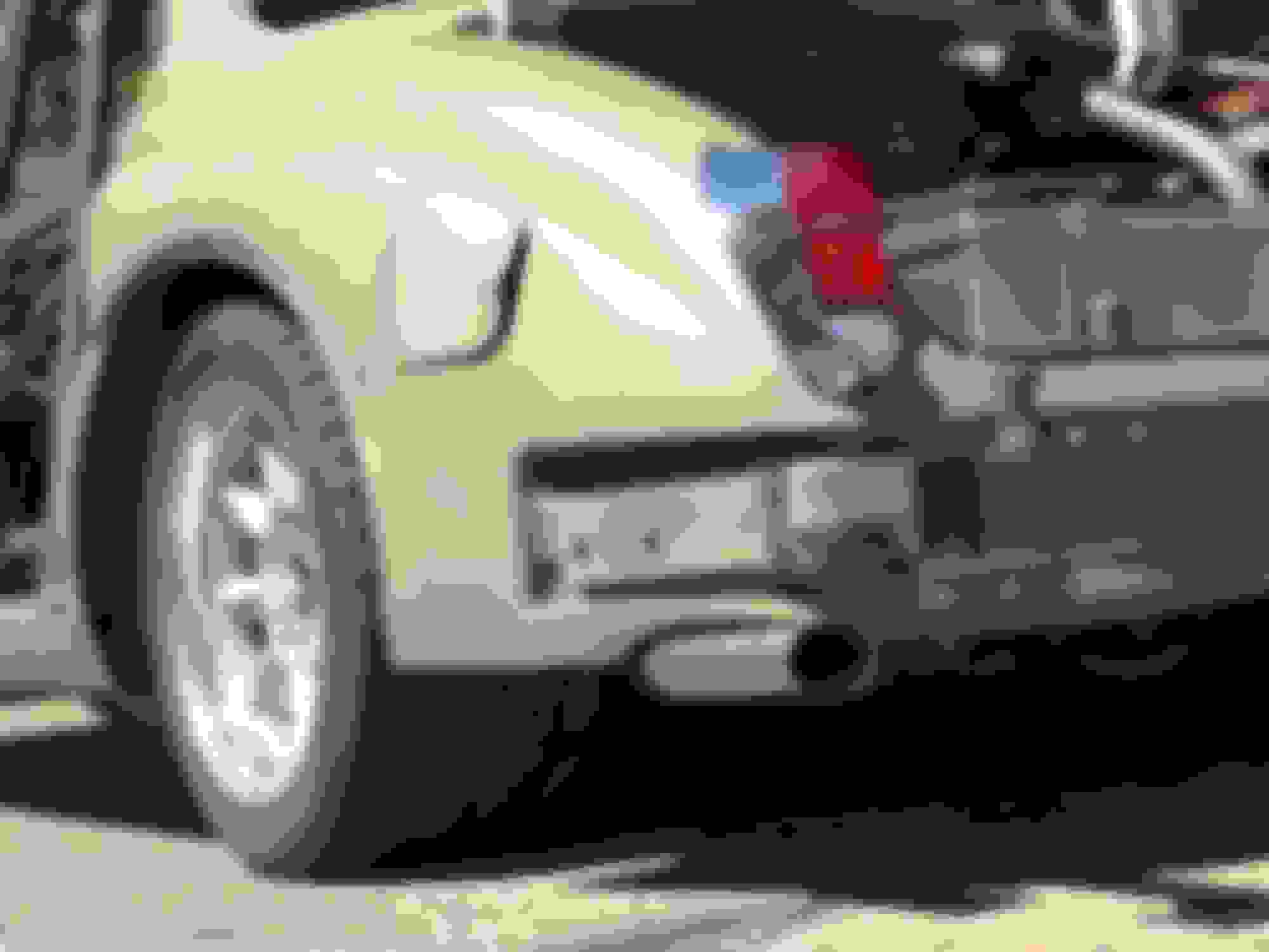
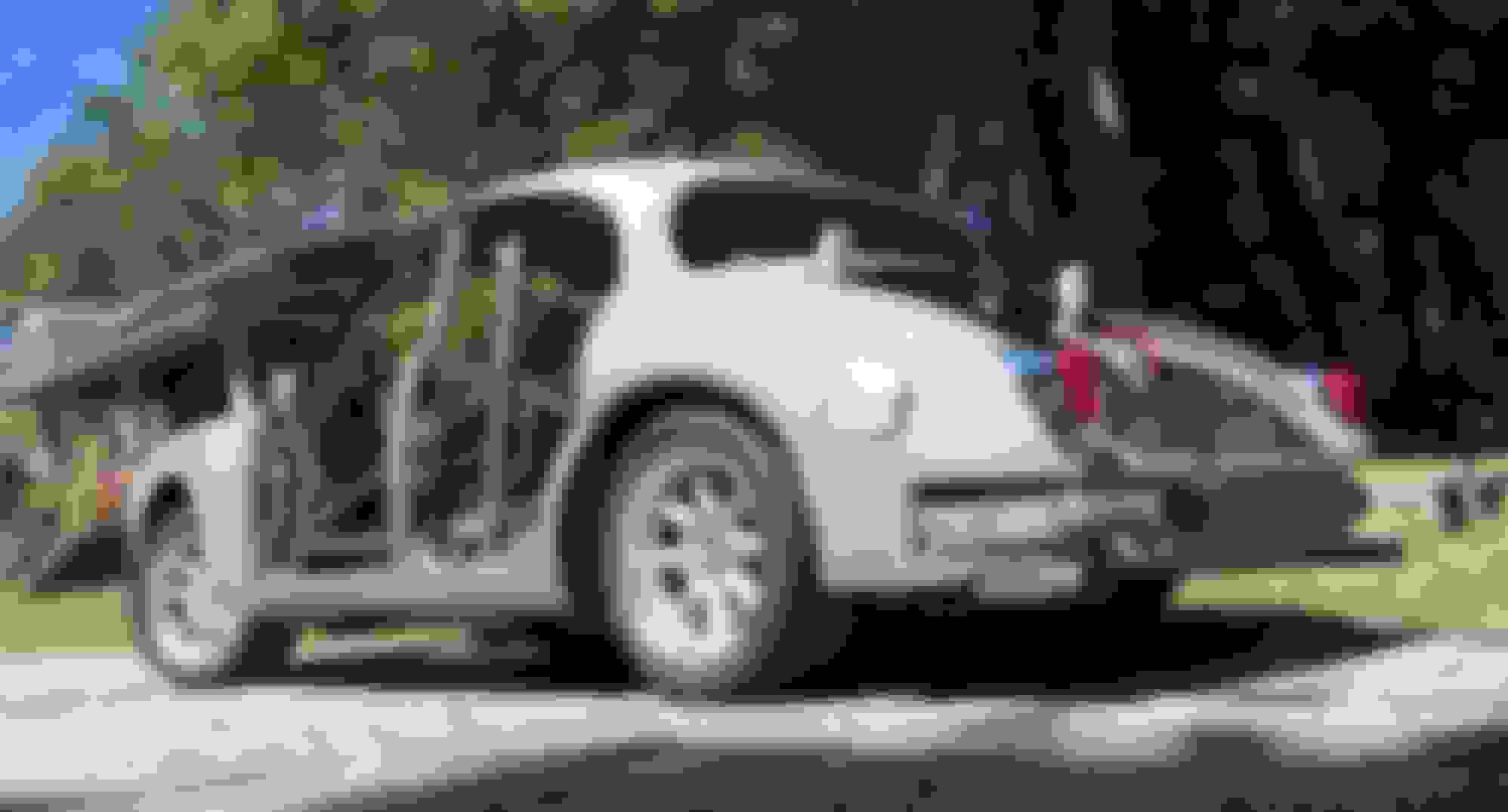
Wheel openings will bee with just lips. It would me grins with the spats, but under certain conditions they would likely rub. It may need wheelie bars.
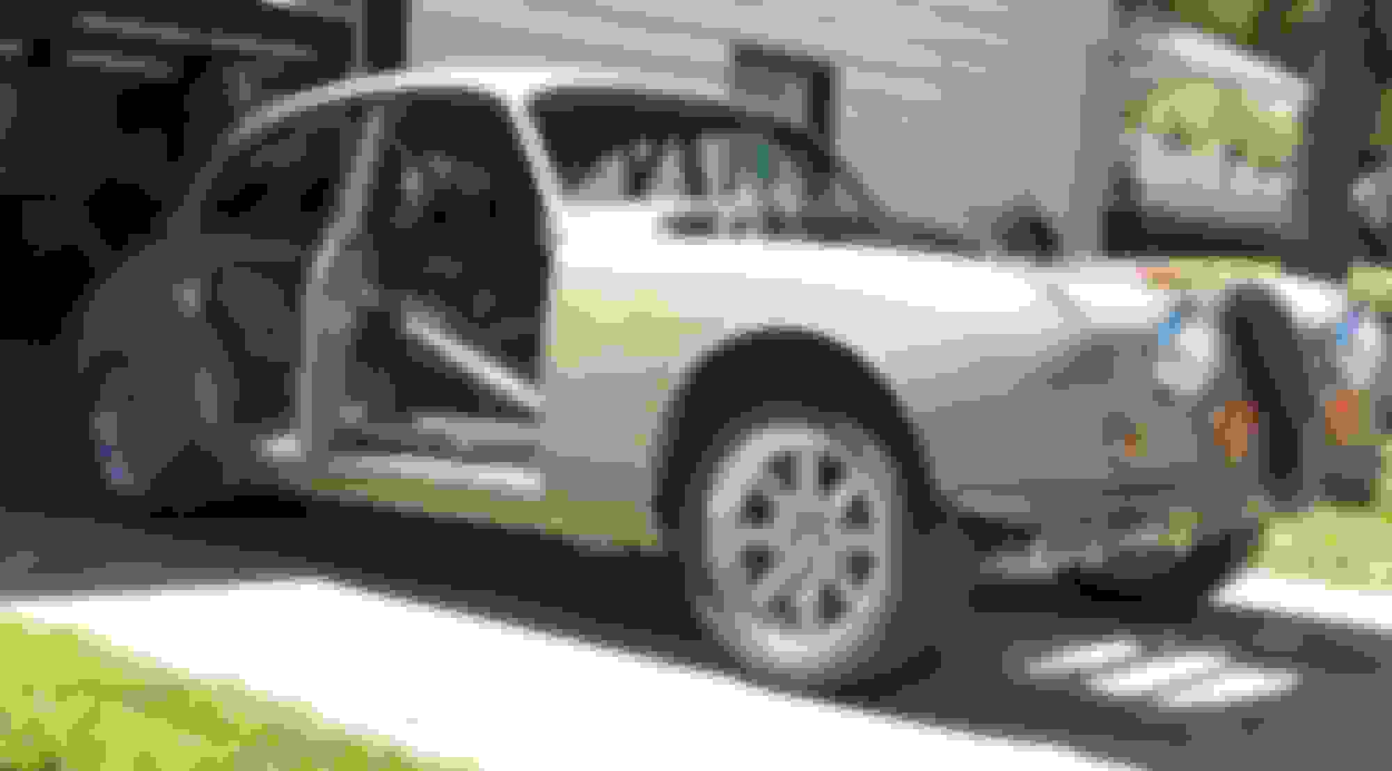
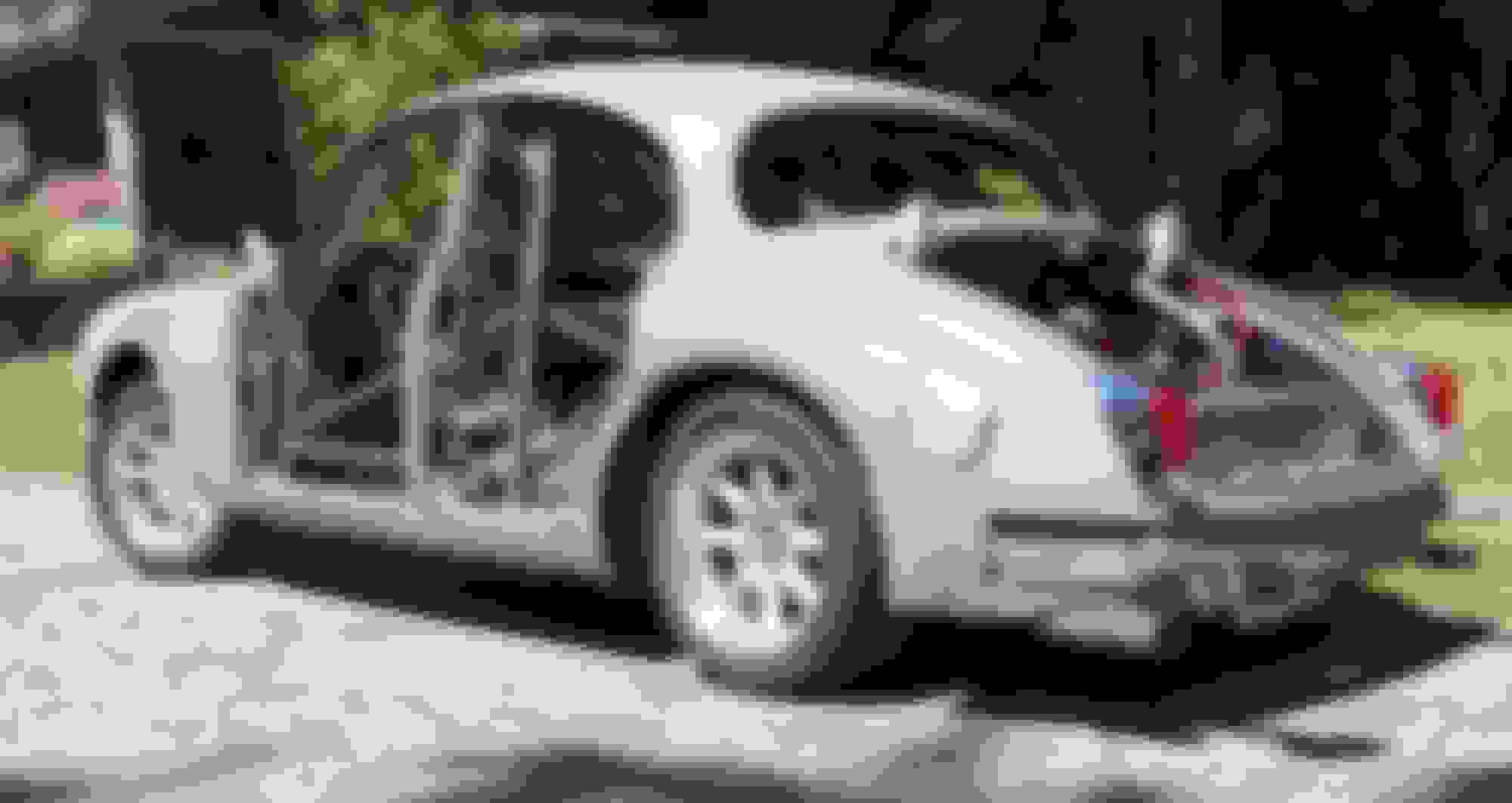
More pictures from today. Wanted to have similar shots to the outside pics from five years ago. Friend is photo bombing in several shots. likely will rub. shots for grins
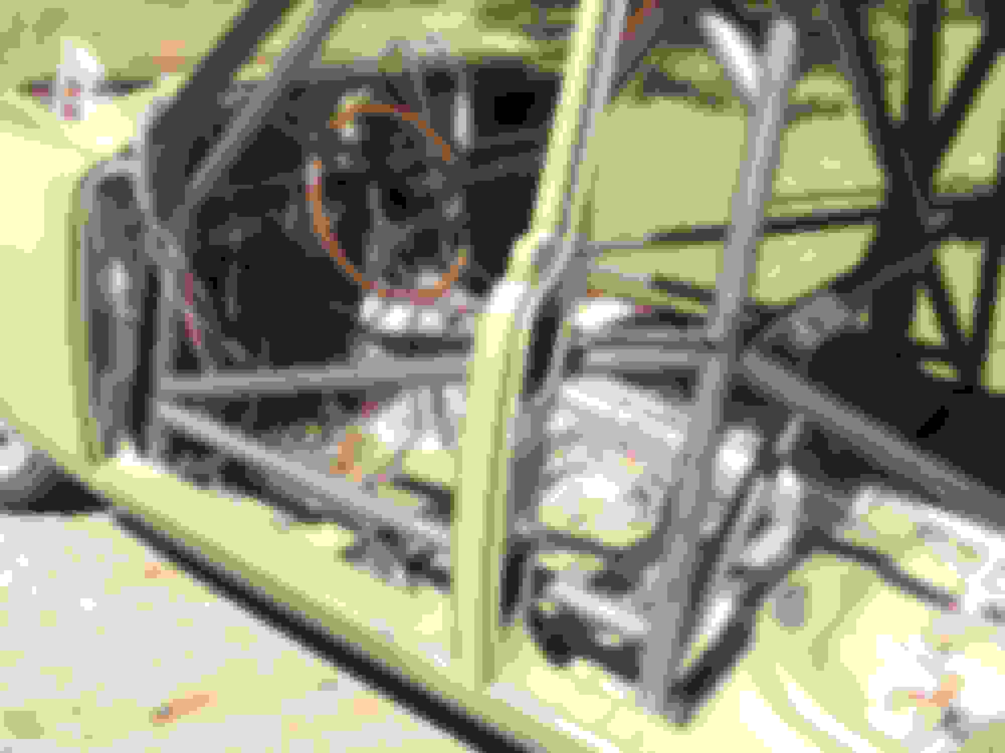
Front chain fall is hooked to the lower control arms
Rear chain fall lifted the rear of the car by the cage.
Looking at the washer imprints to measure for the shifter hole
three guesses - two marks and a pilot hole. Welder made the big "X" a couple of years ago, I made the other marks on Monday this week. Shifter ended up left and to the rear of the marks
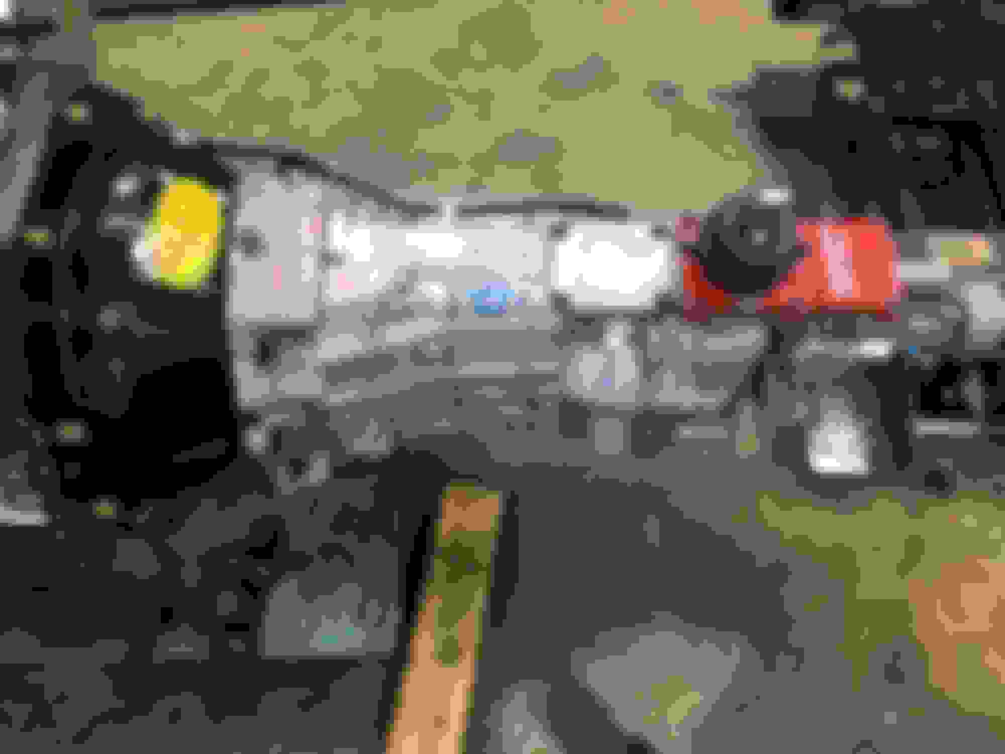
Tremec 6sp bolted up.
There are three choices for shifter position on this trans. Mr. NEWMAN photo bombing and helping
Not enough tilt
The trolley was a must.
"IN"
Carved with a ripping air chisel.
Shifter will sit slightly left and reward in the factory console hole.
Hurst stick arrives tomorrow.
A shoe horn would have been helpful today. Chain falls were helpful for taking the car up & down off the jack stands. I think the front end is officially too heavy for the rafters now. Neighbor Jeff saved NEWMAN and I from ourselves. We cut the shifter hole bigger, dropped the right engine mount, and removed the left valve cover then inched it in the car. A patch corrected the carved hole.
Thanks for looking!
Cheers
Good Evening,
I been working on the marriage of Jaguar switches, AutoMeter Gages, and Painless wiring. Drawing my own diagram has helped, along with referring to factory diagrams for older and newer Mk2's. It was interesting to figure out the SNG Barrett 4 position switch and my 3 position switch using the newer diagram showing both switches. Several times I had to quit and go do something else less painful. All switches except the Washer pump and Fan are wired. I want to put in a small school bus defroster fan facing the driver - just for grins. The "waterfall" panel is also wired. Next up is the toggle switches and the USB mounted to the ash tray cover.
Thanks for looking.
Cheers Drawing to help me understand the "marriage" of systems
Just getting started
Following a suggestion in a Hagerty article - build the dash on the bench!
Blue Sea Buss JB Welded into place
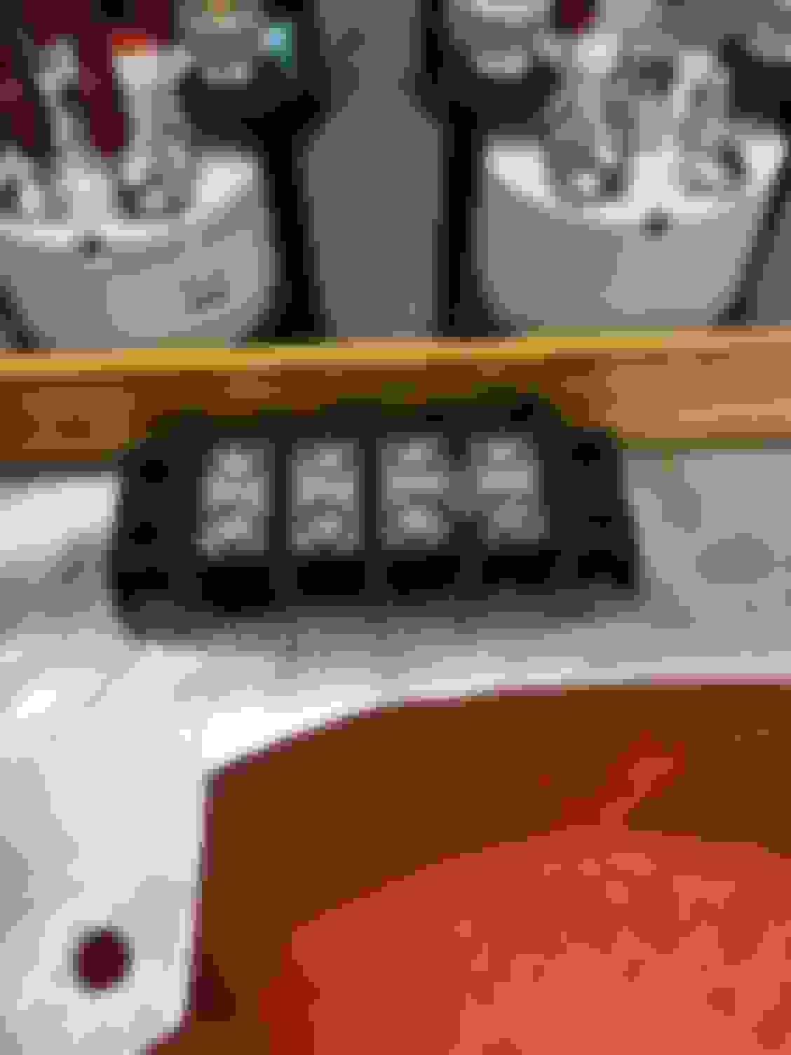
"Waterfall Panel" Engine Vacuum, Wide Band AF gage, and Fuel Pressure across the top. Engine and transmission temperature across the bottom
More toggles. Can't have enough dials and toggles. The only thing that will matter is the shift light! MSD power, electric fans, electric water pump, fuel pump. Two USB ports
Clyde,
Very nice, you must have been an engineer judging from what you would call a hand sketch and we would call as as build engineering drawing of your wiring diagram
Primaz,
Ok, a couple of engineering graphics courses in the mid 60's. Never finished the engineering degree.
Had to figure out a way to mate, Jag switches, AutoMeter Gages, and the painless wiring. Then I decided to put in the SNG four position headlight switch. So I had to merge the 60's three position head light wiring with the late 60's four position diagram with the no diagram SNG switch. The diagram helped me think it through.
Now it's time to fish or cut bait. The center section, tach & Speedo are ready for installation. I need to still prove the air fuel ratio gage operation. Then the waterfall panel will be ready.
Added one more twist, the Tremc requires a reverse lock-out module to operate a solenoid. It keeps the driver from reverse above five MPH.
For additional fun, I just bought a Brother P-touch label printer to code the wiring. The painless harness is marked but hard to read at times. I also added wires, and extended wires with similar color and incorrect markings.
Step away from the project for a couple of days and it's "what was this for?"
As always, thanks for the encouragement!
I knew it. I won't know exactly how far until the hood gets cut. My idea of reforming a second hood may not work either. First test drive with out a hood. No immediate worries. I've been at this for six years.
 06-13-2020, 11:44 AM