When you click on links to various merchants on this site and make a purchase, this can result in this site earning a commission. Affiliate programs and affiliations include, but are not limited to, the eBay Partner Network.
having gone through painting a car a couple of times myself, (and that's the only way someone can appreciate the shear insanity of doing all this work yourself), CONGRATULATIONS! it looks awesome and i bet the feeling you get when you look at the car can't be duplicated. i'm lucky enough to be close to the mexican boarder and have taken a couple of cars to a lifetime restorer down there. he's so busy he won't even touch collision work. pics are my 81 vet and 75 XJ12C both done with unbelievable amounts of work for less than $2K each. pays to not have the epa and a depressed labor force.
heriberto and his guys
'81 vette evercoat epoxy primer and "firemist orange" top coat
Couple of questions. On a positive ground car, where does the white wire go to on the SU fuel pump. The spade ot the top and the black ground (+) wire goes to the spade on the middle? And what is that little metal tube sticking out of the side- some kind of vent or overflow that needs a drain tube?
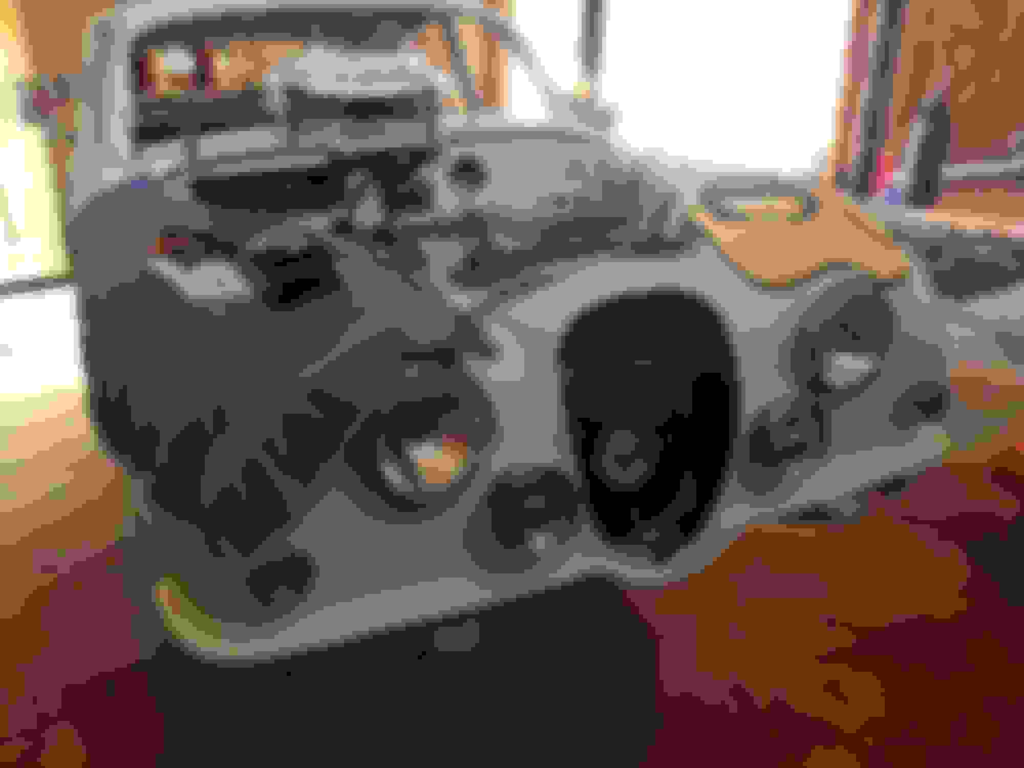
New fuel pump
Also, this part is not standard and I can trash it right? I am pretty sure it is from the old AC system, but thought I would ask before I removed all the wires.
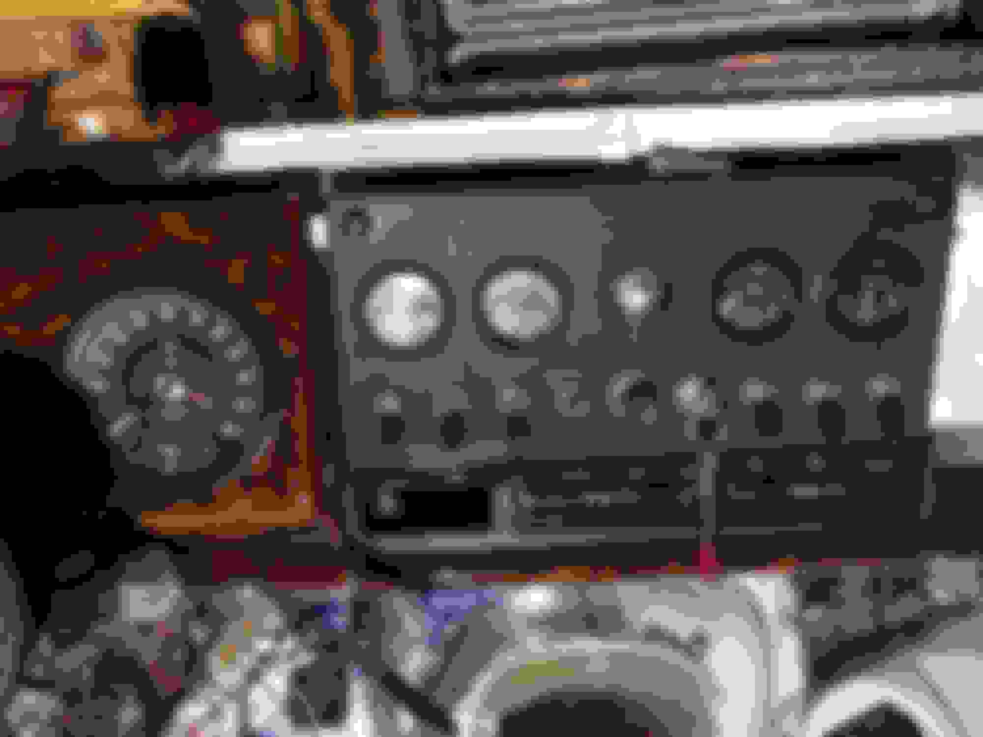
Thanks for the confirmation! I did pull the little switch out- was definitely not original. Pulling it out helped clean up the wiring behind the instruments. This is the kind of work that had been done:
Professional installation
One thing I did find was several green wires from the voltage stabilizer are melted together back into the main harness, so I will have to really dig around in the wires behind the dash, cut them out and install new wires. I think they head over to the speedo/tach, but haven’t gotten that far yet. I know- I should just redo the wiring harness like so many others are doing, but I’m not there yet.
Chuck, when you say several, how many do you mean ? There are normally two wires at -10V relative to ground, and two at -12V relative to ground. The 10V wires are for the fuel and water gauges and the others are main feed to fuse and the oil pressure gauge.
The wires should go directly to the gauges before heading off the the senders.
If the wires are in fact melted rather than deteriorated and stuck together, you need to find the cause of the problem as there may be a short somewhere.
It may be that they have just stuck together rather than melted, the old rubber insulation tends to go gummy and the wires can stick together, they also go very brittle and movement often makes the old insulation just fall off. That was often the reason the old looms failed.
Looked closer at the wires. The melted wires are the two green ones starting at the flasher relay and then into the harness. Looks like one goes to the wiper motor, and one back to A4 terminal on the fuse block. May have to open a lot of harness to replace them. They are definitely melted together anc compromised the grn/purple wire next to them. Perhaps the wiper motor caused them to overheat,but I’ll look for other shorts also. I’ll order some correct color wires to replace them all. Couple of other wires need replacing too.
Meanwhile I get distracted by shiny objects and fun stuff like cleaning and resealing gauges, installing the new battery mount, etc. there is no end of small fun tasks that will eventually end up in a running car.
Bumpers and overriders back from the chrome shop today. They came out very nice!
Question about a couple of wires coming out of the back center of the instrument console. Two black wires that were just twisted together. One goes to ground somewhere, and the other one doesn�t go to any black wires that I could find using a continuity tester.
There are also two white wires that come in and were taped together. Still haven�t found what they may go to. After I get my other wire repairs done, I will put some power into the system, and explore further.
Any idea what the black and white wires are? They come out of the same wire holder as do the flasher relay wires in the back middle of the instrument cluster.
Chuck, looking at the wiring diagram, the only white wires that should be coming to the dash area are the brake fluid warning light & ignition warning light from fuse A3, (there is a joint to both these then going via a single wire to A3) and also the starter push button is fed from fuse A3 with a white wire.
The fuel pump is also white as is the ignition feed to the coil, but these do not go through the dash.
To sum up all white cables are all switched with the ignition and are not permanent 0V (in your case as you are positive ground, if you were negative earth they would be switched 12V), so when tracing, there should be continuity to fuse A3 from all white wires at all times, and then continuity to the battery negative with the ignition on.
It can be more awkward to get your head around negative earth testing and you said you may not fully understand the principles. If you would like me to try and explain it I would be happy to just let me know, I can send you some diagrams and some explanation if you want.
That is helpful. I just need to focus on the basics, and run the wires down that way. I have a wiring diagram that I need to blow up and print so I can take notes on it, and track down all the loose wires that I have.
I spent a couple of hours this afternoon working on getting the blinker switch, overdrive switch, and associated lights hooked up as well as the rear wiring harness. Still have a ways to go. Of course the new blinker switch does not match the old one perfectly, so I’ll have to sort all that out too. Thanks for looking. Just thought the wires coming in by the flasher relay were odd- they do the same thing in the 67 I have...just come in there and don’t connect to anything. Perhaps they are for another option I don’t have, like a heated rear window.
Progress has been pretty slow this month. Lots of distractions, and too cold to want to run out to the barn in the morning and work. Engine assembly has been frustrating because every time I try and make the next step- like installing the head, I can’t get the engine to turn over properly. Finally figured out I am letting the timing chain get caught up- so now I have to get it un-kinked. Hope I don't have to pull the front cover off again, but that is what it looks like.
I finished repairing all the melted wiring running to the wiper motor. British wiring.com has been very helpful with getting the right wires. I have been testing circuits with a multimeter. I finished the installation of the battery in the trunk, so soon I can start testing with power. Just need some warmer weather!
I put in the front lights because it is fun and they look beautiful.
I am also working on installing the new air conditioning system. Lots of time consuming modifications. Fortunately Lin is installing the same type system, and his website is very helpful- much more so than the instructions provided by the company. The center AC vents are nice, but are a little awkward with the cigar box. Lin has a very elegant solution, but I didn’t want to move the vent lever and lose all the storage space, so I blocked off the area behind the vents with a piece of wood, flocked the whole area, and now have a nice little pocket to store a cell phone or small items.
Anyway, hope all your projects are going well out there!
Looking good Chuck, you say it's too cold, but the water gauge is measuring about 55 deg with no engine in, it must be quite warm !
Re Timing chain, have you tied the sprockets and chains up and toward the center before offering the head up? If you do that you should get no problems, some sprockets have a thread on the center pin that you can put a nut on to hold them in place which does make it quite easy.
AC panel looks like an elegant solution, nice job. I have ordered new Fograngers myself, also fancied the idea of seeing some actual nice shiny bits for a boost in the rain and cold.
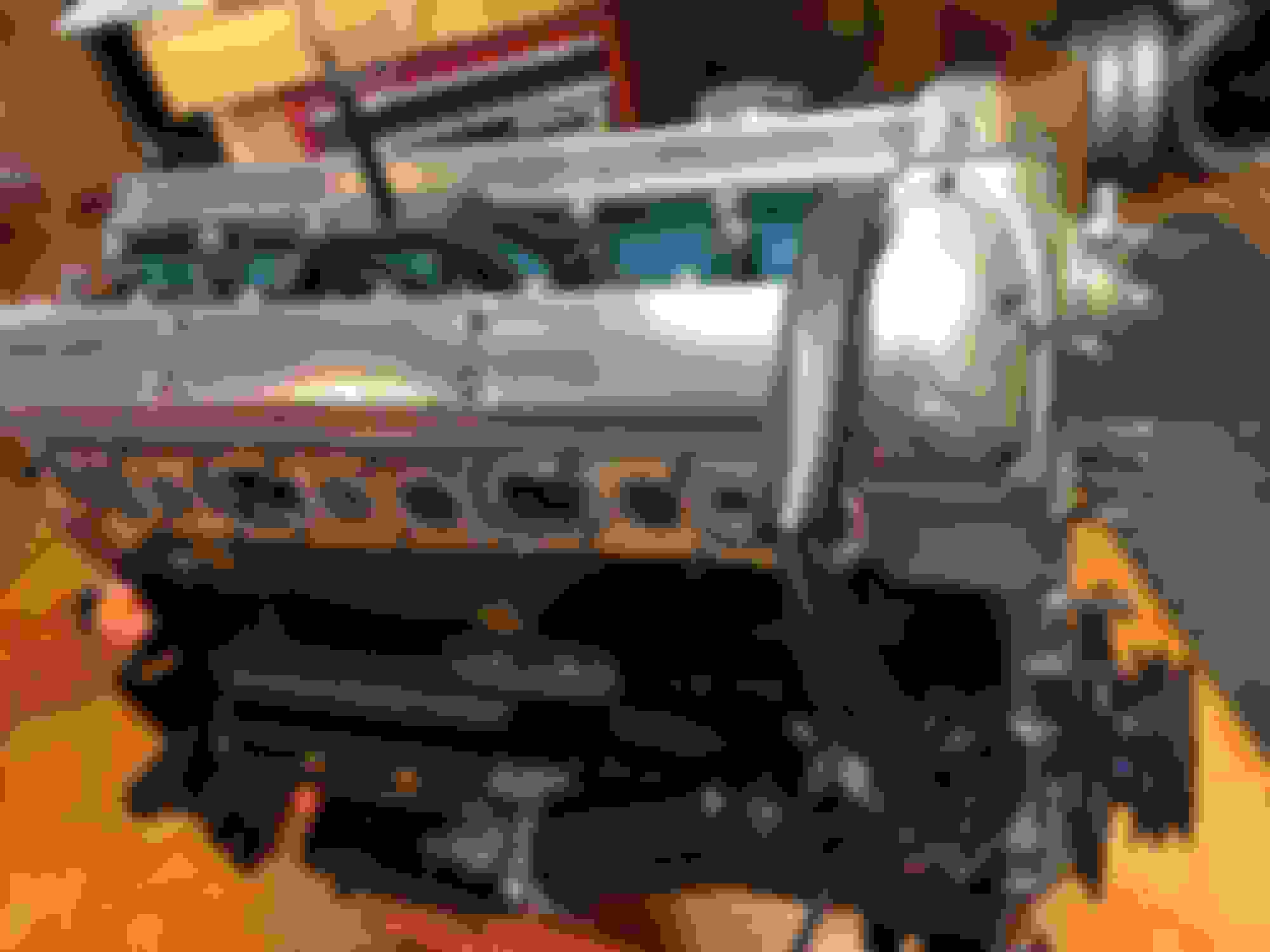
Finally making progress with the engine. Should get it mated up to the transmission in a few days and hopefully back in the car soon.
Head back on and cams timed.
Should any sealant be used on the metal gasket that the intake manifold bolts up to?
My car had a large metal bracket that holds the generator and air conditioning compressor. I was able find a York to Sandeen compressor bracket that bolts directly to this bracket and will hold my new AC compressor. Should be able to get away with one fan belt and the generator being the tensioner.
I will check about getting a better gasket. I used a fiber one on the head and it seems like it would work much better than the metal one that came with the top end gasket set.


 12-30-2017, 07:41 AM