When you click on links to various merchants on this site and make a purchase, this can result in this site earning a commission. Affiliate programs and affiliations include, but are not limited to, the eBay Partner Network.
Diagram of inner rocker, toeboard, floor, front wing to use as a repair guide
Hi,
I am working on a 1961 Jaguar MK2, with rusted front toeboard, rockers etc... Does anyone have a diagram of the various parts that meet in the front, either driver or passenger? I belive the inner rocker curve falls below the floor line, is welded to the toe board but the front wing and A pillar also meet in that area and because both sides are rusted for me, I would love to see if anyone has a drawing or picture exposed of the various pieces meeting in that area.
Those are ace pictures from Homer. There's a piece you can't see in them. It's a reinforcement that I think flares back to join the lower part of the A-post to the inner sill. As is typical in that area, so little remains that it's hard to be sure. I know I keep recommending the Practical Classics Mk2 restoration book, but this is another subject where it helps.
In Homer's 4th photo, you can see the inner wing splash panel (aka rust trap). If you keep that original like Homer's, you have to make sure your patch panels fit around it. You can guess how I found that out! In the end it's not too much of a disaster, as I decided not to use the original splash panels.
To be frank, the original design of the A-post to sill (rocker) is very poor, lacking stiffness and catastrophic for collecting mud and rotting.
Hi Peter, i'm not sure what reinforcement piece you mean, could you elaborate as I might have a photo of it from one of the cars i've done over the years.
The baffle panel on mine was replaced, they usually rot out badly and this car was no exception, the one in the picture was just held on by screws while I fitted the outer wing repair panel.
Homer, Reinforcement wasn't a good description for it. It was probably intended to (help) carry bending loads between the A-post and the sill. It's the panel that extends back from the side wall of the footwell into the space behind the first few inches of the sill. The bottom of the A-post is welded to it. In the picture below, my finger is on the remnants of the one on the left side of my car. The second picture is from below. As the bottom few inches has disappeared, it's not clear as to what it should attach to. Presumably, it's closed somehow and joined to the inner sill.
It's not important to me as I decided to re-design the whole area and put an intermediate sill in my car to make it all much stiffer, especially the connections of door posts to sills. However, for those seeking originality in every detail or prefering not to modify, it may be of interest.
Personally, working on my car has given me a fairly bad impression of the Pressed Steel Company both for the detail design and quality of assembly that they put into our cars.
I know the piece you mean, there wasn't much left of mine but there was no evidence it was ever welded to the inner sill along the return so I assume it just had a return on that was unfixed. I assume it was fixed to the inner still at the bottom but mine had rotted off there like yours (damn the British weather and our salted roads).
When I did my latest MK2 I made this piece a bit longer and left the end open so it was easier to get the rust proving cavity wax in with a tube.
Mine looked looke like this (drivers side work in progress) when I did it.
Homer, that's more or less what I've done on the driver's side of my car, except I've continued the section right through to the rear wheel arch. It's roughly on the lines of the intermediate sill in the S type and 420.
I've found some pictures of one I cut up years ago that was very original in this area.
You can see the end of the piece through the end of the sill and that it wasn't joined to the inner sill. The pictures are a bit odd, the front of the car is on the trailer and the middle/floor is upside ontop of this.
The cut up car looks as if it was less rusty than mine. That piece we've been discussing doesn't appear to do much useful. What structural engineers call a zero member.
The cut up car looks as if it was less rusty than mine. That piece we've been discussing doesn't appear to do much useful. What structural engineers call a zero member.
Yes it was a really good car and I regret cutting it up. I bought it in 2014 for a few hundred pounds as a largely stripped shell because I needed the panel behind the back of the rear panel for a car I was restoring and you can't buy them new.
The cat was a 1967 and had been in an accident in the mid 1970's and hadn't been on the road since.
Its just one of many cars that if I had my time again I would have kept.
Ok, just to make sure I have all of the stated parts:
1) The front inner sill flange is welded to the toeboard, and part of it falls below the floor
2) The front of the floor is welded to the side of the inner side and the front to the toeboard and inner sill flange
3) There is a piece of sorta folded over metal that is welded to the A pillar, and sits inside the inner sill
4) There is a box around the folded over piece connected to the A pillar and front part of the inner sill
5). There is a front piece that sits inside the inner wing, and closes off the front of the inner sill. This is separate from the toeboard.
Did I get that correct or miss something? Thank you all for posting and the commentary.
Owen
1 and 2 above are correct i'm not sure about 3,4 &5 as I don't understand the description.
The footwell side panel should continue down past the top of the inner sill and then turn back in and connect to the base of the inner sill.
In the sketch above green is the outer sill, yellow is the inner sill, red is the section adjacent to the A post and grey is the A post.
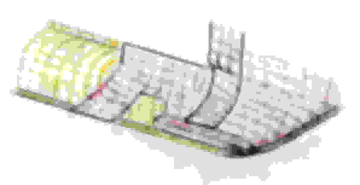
As Jaguar don't provide any pictures that I can find in either the service manual or spare parts book, I've worked up my best idea of what the pieces at the bottom of the A-post looked like. It's on the basis of the remnants on the left side of my car, Homer's photos and drawings, and the pictures in the Practical Classics Mk2 restoration book (page 37). I think it's more or less consistent with the sections that Homer drew. I've kept the same colours as in those drawings: yellow for inner sill, red for footwell side panel and sheet metal extending from it, grey for A-post. I've put a feint mesh on the surfaces to indicate curvature - there are a lot of subtle curves. And the view is looking forward and up to the right hand side of the car.
For myself, I wouldn't bother to try to recreate it on my car and I'm not going to. No one sees it. It doesn't look very stiff and is typical of the poor detailing that the Pressed Steel Company produced for Jaguar (and presumably all their other customers).
A few minor points:
The bottom of the A-post kicks out and then seems to follow a curve. I suspect this served to meet the outer sill and close the front of the box formed by the inner and outer sills. I don't know if the outer sill was welded to it. If so, I suppose it must have been gas rather than spot welding. For restoration purposes, it's better to make the bottom of the A-post too small to meet the sill and make a piece to fill in between it and the outer sill.
I think the wiring harness passes out along the sill through the rearmost space between the red and yellow panels.
I've drawn the bottom rear side of the A-post as open. I'm not sure if it should be, but the remnants on my car suggest it. I'd definitely close it for strength and stiffness.
Be aware of how the bottom front of the footwell side panel curves in towards the inner sill. It has to clear the complicated closing panel (yet another horrible mud trap design) that welds to it and the front wheel arch.
And please feel free to improve and correct, Peter

 07-04-2022 | 05:23 PM