When you click on links to various merchants on this site and make a purchase, this can result in this site earning a commission. Affiliate programs and affiliations include, but are not limited to, the eBay Partner Network.
As a side tangent to the recent discussion of T5 conversions, I visited my car this weekend and I changed out the drive( prop) shaft. I have had a shaft made in order to incorporate a CV joint at each end, as my driveline angles were wrong.
As a quick summary, the angle across a universal joint should be at least 1/2 degree and no more than 3 degrees. Also, the angles across joints at each end of a shaft should differ by no more than 1/2�. For example, if the angle between the differential pinion and driveshaft at the diff end is 2�, the angle at the other end of the shaft must be in the range of 1.5-2.5�. Mine was almost zero at the diff, and 3 degrees at the transmission, measured in the vertical plane. The shaft is also not parallel with the centreline of the car, as the diff pinion is not on the centre, so that angle in the horizontal plane also needs to be accounted for.
The reason I had the unequal angles is I couldn't raise the rear of the T5 high enough into the body, so the tail was drooping. The solution was to use a constant velocity joint, as they are insensitive to angle differences.
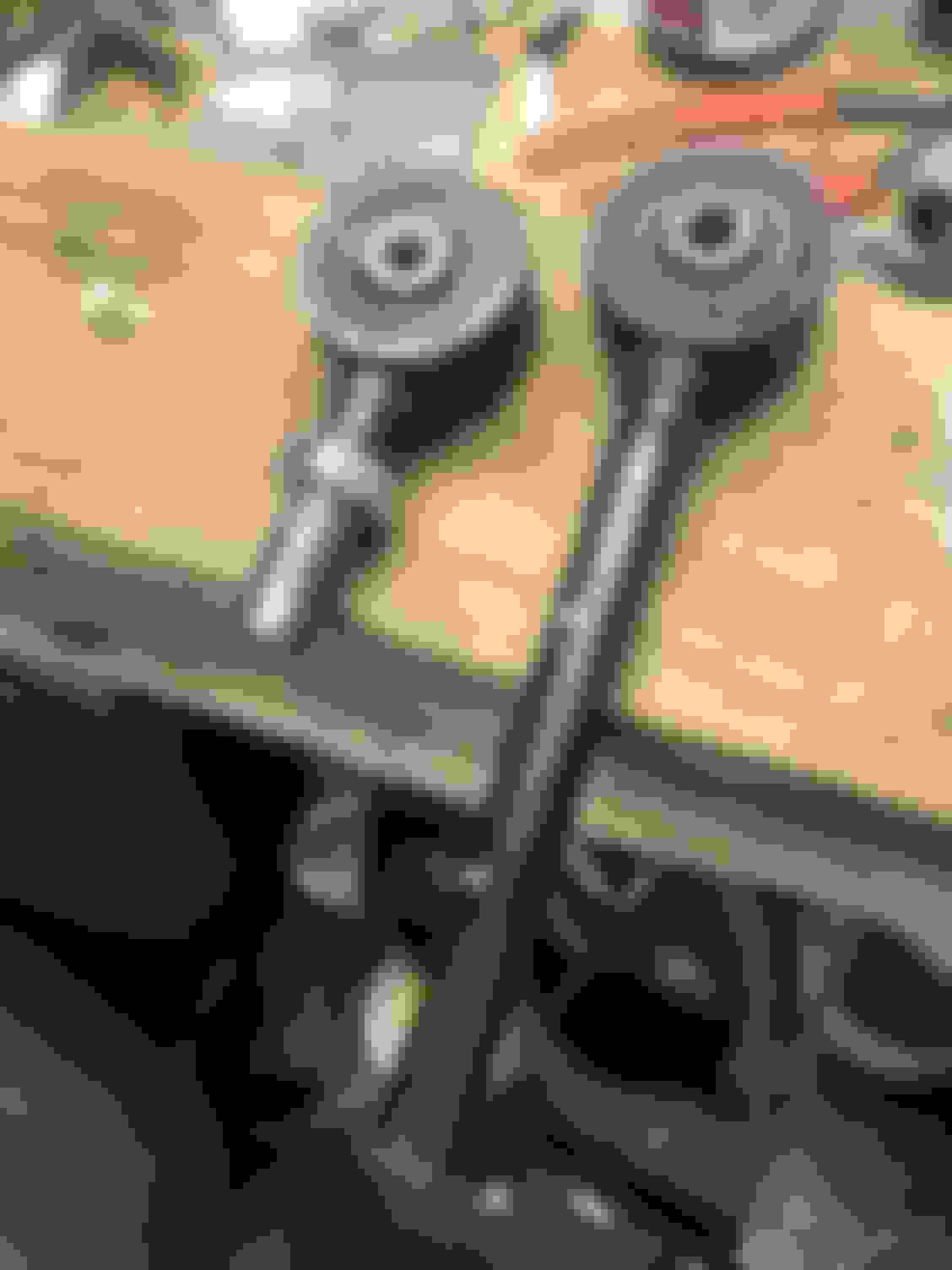
I retrofitted an XJ40 flange to the differential to enable the use of the rubber Jurid type coupling. The early XJ40's in 1987 used an adapter to convert the old style differential to the new style until revised differentials were available. It consists of a new flange and in insert that has a centering pin and snap ring. The later cars have the centering pin integral with the pinion. The tube portion of the shaft came from a Land Rover Discovery, as they use a similar coupling. The other end is a CV joint from an AWD Ford Escape, and I had a driveline shop weld them together.
To adapt to the transmission, I obtained a yoke from a 1969-71 Mustang, as these have a very long splined tube, about 9" long. Then I took the mating hub for the CV joint from the Escape and turned it to a size where I could heat shrink it onto the Mustang splined tube. This ensures that there is good engagement of the splines on the output shaft of the transmission and it keeps the hub concentric.
After bolting everything together I went for a short drive, taking it up to 70 mph. So far there is almost no vibration, so I think I have cured the driveshaft vibrations. Next is getting the wheels balanced properly, as I'm sure they are incorrect as I have 6-7oz or weight on each wheel.
Very Good. Mercedes uses CV joints at both ends of the propshaft & both ends of the side shafts then you don't need to worry about angles & drive is as smooth as a babies bum. You can also use a plunging CV joint at the normally splined "centre" piece in the propshaft & a centre bearing (both Opel & Merc do this). If you do this shaft length becomes more crucial than normal as there is a limit to Plunging CV Joints available. Most stay with the conventional "centre" spline.
I'm impressed & enjoy your smooth transmission of power to the rear wheels. No more UJ angles to worry about.
Last edited by Glyn M Ruck; 06-06-2022 at 06:20 PM.
Thanks! One thing to note about the rubber Jurid ( or Guibo in BMW/MB speak) coupling is that while it is a CV style joint, it is designed to tolerate up to about 1� of angle. Greater angles require the Rzeppa style joint, which is what Jaguar uses in the X Type.
Another "gotcha" along the way is while the external pinion seal diameter is the same between S Types through to X300's, the inner shaft diameter of the seal changes. The S Type (and E Type) sealing diameter of the companion flange is smaller than the XJ40/x300, so a later pinion seal needs to be used with this adapter flange. A Land Rover seal is cheaper than the Jag seal, part number AAU3381.
Interesting. I've only ever used genuine S Type Pinion seals. Thanks for that tip/info. I have a spare pinion seal on it's way from Barratts now ~ a final shipment of nick knacks of normal spares. They are made from a synthetic leather like material. When I first drove the car after restoration I had a slight pinion leak. I was going to add some seal swell additive (2%) to the oil but never got round to it. The leak has stopped. The oil is at correct level and I did soak the seal in diff oil overnight prior to fitting. Anyway while it does not leak I shall leave well alone but have a spare if needed in future. I worked hard on the mesh & pinion pre load on that diff & it's dead silent.
Last edited by Glyn M Ruck; 06-07-2022 at 12:16 PM.
I worked hard on the mesh & pinion pre load on that diff & it's dead silent.
I've rebuilt the differential in my XJS and it's silent too. It was a matter of taking my time and making sure absolutely everything was in specification. I measured everything 3 times to make sure the result was both repeatable and accurate. Diffs are a matter of patience I think, it's not a job that can be rushed.
Yes ~ it's all a matter of attention to detail. My diff had done 90 thousand miles with some caravan towing & is dead quiet set up properly. Original crownwheel & pinion.
BTW ~ Benz uses a combo of flex discs, proper CV Joints & plunging CV joints. Their flex discs will do a lot more than 1 degree & do in practice even on a simple old W203. A matter of design.
4 Matics are even more complex with the driveshaft running through the engine sump.
Last edited by Glyn M Ruck; 06-07-2022 at 04:11 PM.
Yes ~ it's all a matter of attention to detail. My diff had done 90 thousand miles with some caravan towing & is dead quiet set up properly. Original crownwheel & pinion.
My XJS had about 90,000 miles when I rebuilt it. It was a limited slip and the PO had broken the cross shafts, so it was effectively locked all the time. Made it very tricky to drive in the wet. The crown and pinion was the only thing I kept; I replaced everything else, including the case which was distorted. I managed to find a 1986 Sovereign at the junkyard, and took the differential from that. I changed the gears to keep the XJS's 3.54 ratio and the differential mounted pickup for the speedometer.
As you can see, it wasn't in the best shape when I opened it up.
I'm in a situation similar to where Jagboi was in the original post. I have converted an automatic to a T5 and the angles are all wrong. I have a Jaguar flange on both the transmission output and (of course) the differential. The transmission angle is 3.5 degrees down and pinion is about 1 degree down. Add in the slope down from the difference in height and I have a pretty big problem at the pinion. The math says that the drive shaft angle is about 4 degrees down from the transmission to the pinion. Given this, a standard U-joint could work pretty well at the transmission end but 5 degrees (4 +1) at the pinion is a mess. Has anyone had any luck rotating the rear axle? With fixed length on the upper locating arms, the only adjustment is at the spring. Seems to me that there is not much that can be done there and the center bolt through the spring leaves (leafs??) is centered in the mount. I assume the pinion must have pointed up a couple of degrees or the factory drive shaft geometry would have been way out. Being an automatic, the original setup used a center bearing about 18 inches from the transmission, making the angle even steeper.
Maybe the answer is to find a competent drive shaft shop and see if they can add a CV to the pinion end.
I suspect it's probably easier to adapt CV joints of some kind to the driveshaft. For conventional U joints, you want the angles across each end of the driveshaft to be within �� of each other. So if the angle is 2 degrees at the diff, the allowable range at the transmission is 1.5 to 2.5 degrees.
A 2 piece shaft may be the answer for U joints if you can split the angles to make each joint an equal angle. CV joints cure all the problems though.I've given some thought to converting a different Jaguar to CV's and I think machining an adapter disk so it can bolt to the Jaguar flange and then bolt to a CV style drivehsaft is probably the easiest. Audi and BMW usually have CV style joints, depending on the vehicle. A look at the Rockauto catalog can be useful to see what cars have what style joints.
I had a similar problem while setting up my 65 Daimler 250 to accept a small block chevy engine backed up by a T5. With the chevy engine, the t5 wanted to be around 3.5 degrees down and my pinion angle was about 1 degree up and then there is the off center issue. I didn't want to go with CV or Double Cardan. because of cost and eventual maintenance issues. So I decided i would rotate the diff to the same angle as the t5.... to do this i fabricated adjustable torque arms using the existing torque arms and some 7 inch swedge tubes from speedway motors. The swedge tube has 3/4-16 RH threads in one end and 3/4-16 LH threads in the other end. I cut the existing torque arm leaving about a 2 inch "tail" on the bushed end, on each end. I then cut LH threads on one and RH threads on the other.
After installing my adjustable torque arms, i simply adjusted them until the pinion angle matched the angle of the t5. We're just talking a few degrees, so the swedge tube rotation is just a few turns.
With the t5 and diff at 3.5 degrees I had a driveshaft made with stock 1310 u joints, stock pinion flange, t5 28 spline slip yolk, and 47 inches long. When i installed the drive shaft, to my surprise, it was sitting at 3.5 degrees. So i ended up wit a driveshaft working angle of 0 (at both ends) in the verticle plane and about 2.5 degrees in the horizontal plane (offcenter offset).
Thanks, Steve. That looks like the perfect solution. I was thinking about adjustable torque arms but don't have my own machine shop. I would have to find a machine shop to make them for me and that is probably big bucks. Did you have to turn down the torque arms before threading them? Did you use a standard die to create the threads or are they machined in? I have threaded stuff before but never anything that big.
My T5 is also at 3.5 degrees down but has a Jaguar flange. I calculated the drive shaft itself would also be about 3.5 degrees down, same as your. I would need to have the slide in the driveshaft itself but that is how the factory did it so probably not a big deal.
I still have to figure out how to mount the rear of the T5 to the body but that is likely something I can make on my own.
Thanks, again!
Craig
Machine shop is not necessary. the torque arms are .750 diameter..Mine had some surface rust which i cleaned up with a file. I cut them with a hand hacksaw, I did use a bench grinder to chamfer the end before cutting the thread. I had the RH die in my tool box but not the LH die... I got the LH die from https://www.msdiscounttool.com/catal...ucts_id=101211 If you need a die holder generally referred to as a die stock, they have that also. You need a good bench vice to hold the torque arm ends while you cut the thread.... the big die is a split die that has an allen screw that affect the depth of the cut.. start out with a shallow cut and go deeper on successive cuts until the jam nut threads on snugly but loose enough to thread by hand.... the swedge tube you can get from https://www.speedwaymotors.com/3-4-I...sku=91034534-7 .....they also have the 3/4 16 left hand jam nuts.
Ace advice from Steve. All I can think of adding (assuming you don't have much experience with taps and dies) is to make sure everything is nice and square as you start the thread, squirt a little oil on the die or tap, occasionally reverse especially when things feel a bit tight, and don't be afraid as, performed with care, it's quite easy to do.
as peter said, take your time getting it started, i like to chamfer the end at about 60 degrees for about a 1/4 inch from the top. i just eyeball it, doesnt have to be exact.. and i use LOTS of oil applied with an old 1/2 inch paint brush.... i use chainsaw cutting oil but any kind of oil will do. once started and down a few turns i never go more than a full turn on big dies without backing up a bit. use the oil brush to remove the metal chips as you go.
as far as using an output flange on the t5.... I have not seen that ... does the flange slide like a slip yolk? or is it held in place with a nut like most flanges?
My t5 is a WC mustang t5 with a chevy S10 tail housing and shift forks. I used the S10 setup to move the shift lever forward to a position similar to stock for the daimler ...I used a transdapt S10 transmission crossmember to hold up my t5. it comes from transdapt 36 inches long. i cut it down to about 23 inches to fit between the frame rails, then made a couple of 3/16 end plates. I bolted the end plates thru the frame rails then bolted the transdapt crossmember to the t5 while propping the t5 at 35 degrres. I tack welded the plates to the crossmember with everything in place with my little 100 amp welder. i removed it with end plates in place and took it to a certified welder and had him finish weld the plates.
Thank you, gentlemen! This is excellent and I think I will give it a try. Thanks for the links, also.
My T5 is new. I bought a kit from American Powertrain several years ago. They were (and I think still are) doing business as The Driven Man. The kit was supposed to include the trans mount but it arrived without one. After many calls, I gave up on getting one from them. Seems that they don't actually have it. The internals are beefed up to take the extra torque. The 1-4 ratios are the same as the Jag synchro box of the era and the 5th is a 0.73 that should work well with my stock 3.54/1 differential. The shifter seems to be in an ideal location. I did not have to do any cutting to the auto trans tunnel, aside from the hole for the shifter, to make it fit. It seems like the upward movement of the engine/trans is limited by the firewall and back of the engine, not by the end of the transmission.
The T5 output is the same as the diff flange and is fixed. No slide incorporated in that. The plan is to use my existing auto trans drive shaft with the built in slide and have them extend it 18 inches or so. Maybe an all new shaft with my flanges makes more sense. I have not contacted a drive shaft specialist to see what is available.
I have cut threads before but not on anything this big so I was a little nervous about that. Your advice is excellent.
I'm assuming that moving the pinion from down 1 degree to up 3.5 degrees will not move the axle back a significant amount as it pivots on the ends of the leaf springs?
I am a little nervous about using CV joints but maybe a quick call to the drive shaft shop will either push me toward a CV joint or the adjustable torque arms. I'm definitely leaning toward the modified torque arms since it seems like 3.5 degrees up would create the perfect geometry with the horizontal offset providing the degree or two that the u-joints like to see in operation.
Again, thank you all for the excellent input. Everyone has been so helpful with my questions over the years. Looking forward to having the car on the road sometime next year. It is a nut and bolt restoration of a very solid car and I want to do it right.
Another question. Why is the opening for the manual trans so huge? I'm not seeing any reason to get to the top of the trans from inside the car. The filler, drain, speedo take-off an reverse light switch are all easily accessible from the under side of the car. With the fairly small hole that I cut (maybe 8 inches round) I should be able to adapt a gaiter without having to make a fiberglass or metal cover. Is my thinking sound on this?
Thanks again,
Craig
The large opening probably isn't essential but is convenient for manufacturing and maintenance. It allows access to the reverse and top gear switches, spring load on the reverse detente, the connection of the stick to gear change mechanism, and it's possible to take the lids of the box without removing it from the car. It will also simplify alignment issues when putting the body and engine-transmission together.

 06-06-2022 | 05:04 PM