When you click on links to various merchants on this site and make a purchase, this can result in this site earning a commission. Affiliate programs and affiliations include, but are not limited to, the eBay Partner Network.
Dear All,
My Mk2 has DG auto transmission and hence has the subject switch mounted on the upper steering column.
The start function works: short circuit between switch connections 1 and 3 when in P or N. The reverse lamp function does not work: no short circuit between connections 2 and 4 when in R. I refer to the apparently corrected connections and not those in the workshop manual circuit diagram (apparently incorrect).
It�s not an adjustment problem: the reverse function doesn�t occur in any rotational position of the switch.
I have the following queries
- The circuit diagram shows also a �reverse light switch�. Should this be present on my car? If yes, where? I don�t understand why there would be 2 switches in series.
- I�ve seen a post saying the subject switch is repairable. Can anyone provide any tips eg. how to open the housing, what parts are inside?
try placing the gearshift in Reverse, ignition ON, loosening the switch, then slowly moving it forward and backwards while someone watches the reverse light.
try placing the gearshift in Reverse, ignition ON, loosening the switch, then slowly moving it forward and backwards while someone watches the reverse light.
Please explain what you mean by forwards and backwards.
these switches have two adjustments, one adjustment is not documented in the shop manual, at least the second adjustment isn't in the S type's shop manual with the DG250.
One is the Rotational adjustment that you already know,
the second one is a forward or backwards movement of the switch in relation to the length of the shifter arm's connecting rod.
I am not sure about the MK-2 with the DG250 but that is why I said "try".
In my '65 S type, I discovered the forward / backwards adjustment turned the reverse lights ON.
I have the BW35 gearbox where the inhibitor switch is mounted on the side of the gearbox but they use a similar inhibitor switch. The inhibitor switch for the DG250 is under the dash and I am not aware there is another switch on the gearbox for the DG250.
First of all this is not a complicated electronic gizmo switch it is as basic as basic can be.
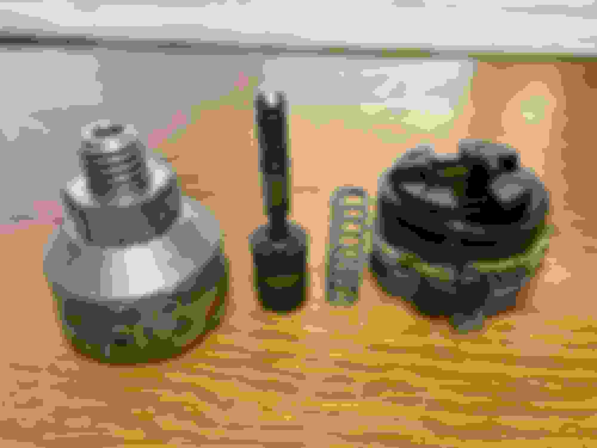
Below are some photos of an old one I had problems with a couple of years ago from my BW35 S Type. I pulled it apart as you do to see how it works and ended up buying a new one as they are only �35 from SNG.
It consists of four parts. An aluminium housing. a plunger that has an isolated area either side of a brass band, a spring and lastly a plastic end where the wires connect.
The way it works is the aluminium end on the BW35 screws into the side of the gearbox where a lever pushes the plunger in a certain depth depending on which gear you have selected. Adjustment is made by either releasing the screw in or out until the lever is pushing the plunger to the correct depth. The whole of the aluminium body has to rotate to screw in or out and sometimes the wires get tangled and have to be disconnected to allow it to be screwed in then reconnected. The plunger in the aluminium body is spring loaded so is always trying to go to its max length. The simplicity of the switch is that in the plastic end there are four brass tabs that correspond to the four electrical connectors on the end which are numbered 1 through 4. Two are for the ignition tabs 1 and 3 and two are for the reversing light tabs 2 and 4.The tabs are slightly off set so when the plunger is pushed down the brass ring only allows current to flow between tabs 1 and 3 or if pushed further down 2 and 4.
So if the plungers brass ring is at a position where it is not in contact with any of the tabs then the car is in gear and cannot be started. When the plunger is moved so the ring touches tabs 1 and 3 the car out of gear in park or neutral, and the ignition button will work. When the car is put in reverse gear the plunger is moved again and the brass ring makes contact with tabs 2 and 4 allowing the reversing light circuit to connect and the reverse lights come on.
I am not sure what Jose is referring to when he says there are two ways to adjust the switch as there is only one and that is to either screw the aluminium body in or out of the gear box until it is set at the correct depth. The adjustment is minimal and difficult to achieve. First the wires for the ignition and reverse lights have to be connect correctly to the plastic end of the switch and then the depth has to be adjusted as per the manual. I used a bulb with two wires that I could run across between terminals 1 and 3 with the car in neutral then 2 and 4 with the car in reverse whilst the ignition was on so when I had the plunger at the correct depths the bulb would light telling me I had the correct connections.
To check continuity between 1 and 3 then 2 and 4. Connect a continuity tester between 1 and 3 and push the plunger down until you get a reading. Repeat this with the tester across 2 and 4. If you have a connection between 1 and 3 by doing a continuity test but no connection between 2 and 4 for the reversing lights the switch is so simple that it could only be a break in the brass circuit or dirt in the switch. Taking it apart and cleaning it is not a problem but resealing it after is a pain as I tried that with araldite on the one in the photo. In the end I bought a new switch.
I have also attached a blow up of the area on the wiring diagram showing the wire colours. WR is white red and WU is white blue. These are from the ignition starter button. G is green and GN is green brown and these are green live in and green brown is out to the reversing lights.
Hope this helps.
Aluminium body , plunger with brass ring, spring and plastic end cap. Plunger with brass ring. Plastic end cap with electrical tabs at different depths. Wiring diagram of inhibitor switch.
Dave the principal behind the switch is going to be the same but instead of a plunger it will have a rotating barrel with the electrical connections so when the arm is rotated it will touch the electrical tabs inside to create a circuit between either 1 and 3 or 2 and 4 to allow the car to start and the reversing lights to come on.
When mine stopped working it was due to bad connections between the spade connectors on the base and the internal connectors. I tried to re-solder them but to no avail. With the BW35 one it is on the side of the gearbox and subject to all the crap coming up off the road. Yours is possibly just suffering from old age and needs a good clean. Sorry you can't get a new one and you are right I have just searched high and low but can't find a new one for sale. You need someone breaking a Mk2 with the DG250 box and buy the inhibitor off them. Buy two and have a spare as they no longer make them new. Strange that they make a new one for the BW35 but not the DG250 perhaps because the BW35 was used in so many other British cars from BL. Have you spoken to SNG or David Manners. They might be able to point you towards where you could buy one.
If you can't find a replacement and can't fix the old one you can always by pass the reverse light side of it. Install a separate switch under the dash and connect the Green and Green Brown wires to the switch to turn the reversing lights on and off. As long as the inhibitor side is working on the starter button you should be fine. Can't say I have ever had to use my reversing lights to actually see when reversing.
Cass, Thanks. I fully agree with your thoughts. I’m just hesitant to risk more damage by opening when the most important function is working.
I'm not sure how the German equivalent of the MoT would react to a manual reverse light switch but I can find out.
Dave
Cass, I have been describing the adjustments of the Lucas Neutral Safety Switch mounted to the Steering column, not the transmission switch which I am not certain the DG250 has.
Cass, Thanks. I fully agree with your thoughts. I�m just hesitant to risk more damage by opening when the most important function is working.
I'm not sure how the German equivalent of the MoT would react to a manual reverse light switch but I can find out.
Dave
Not sure about Germany but the UK does not have MOTs on our older vehicles so we could get away with it. I also think a reversing light is classed as an auxiliary light like fog lights and is not included in the UK MOT.
In the old days we used to put a spot light on the back bumper with a separate switch and the only stipulation was it had to have a warning light on the switch to show the reversing light was illuminated.
It might be possible to rig up a microswitch to be operated by the column stalk. The series XJ automatics use the same switch as that on the manual gearbox cars. It's arranged so the gear lever mechanism hits the plunger.
I have struggled with that switch in my car as well, and I remember wondering if the wiring diagram was wrong or if it was my car. I dont think you would run into too much trouble disassembling the switch. I would expect that its just a matter of a good cleaning and aligning the contacts inside. I will also suggest Vintage Jag Works in Blackfoot Idaho for a replacement. Their site is Vintage Jag Works.

 01-26-2024, 03:46 PM