

DIY Climate Control fix for jaguar s-type 2003+ FAQ
#1
 05-09-2010, 04:46 PM


My DCCV broke, and after replacing I found out that my climate control module was now broken (because of the DCCV). For an indepth explanation of my symptoms and what I did up until doing this repair, see this thread https://www.jaguarforums.com/forum/s...ad.php?t=36503 .
Thanks to Brutal on this forum for telling me that it can be fixed by a PC repair company (I actually own a network consulting firm). So with that knowledge I figured I would take a stab at it, what's the worst that could happen? Broken climate control module (just buy one on ebay, $150 or so if you can find one...)
Okay, so here are the pics and the steps. may come in handy if you don't have a jtis CD and don't know how to remove the trim because of it (lolrd knows I was worried).
You need to replace your DCCV first, because the board doesn't burn itself out. I noticed that when checking the DCCV when it is unhooked from coolant, it cycles when key is clicked to on position. Just look in the holes and you will see it move. Mine only moved on one side, so my climate control unit was bad.
Tools needed, solder, soldering iron, some small wire, a few torx bits for the center console, and some tiny torx for the climate control circuit board (or just cut a groove in them with a dremel tool like I did, and remove them with a flat-head screwdriver). 8mm socket (I think) to remove the climate control and radio unit from the dash.
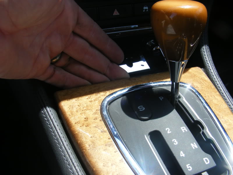
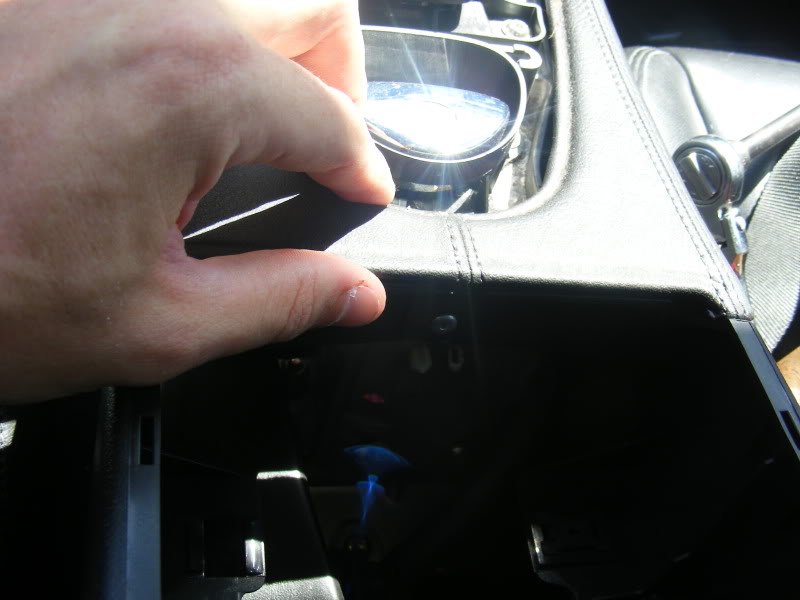
First step, remove shifter trim by opening ash tray and pulling up like so.
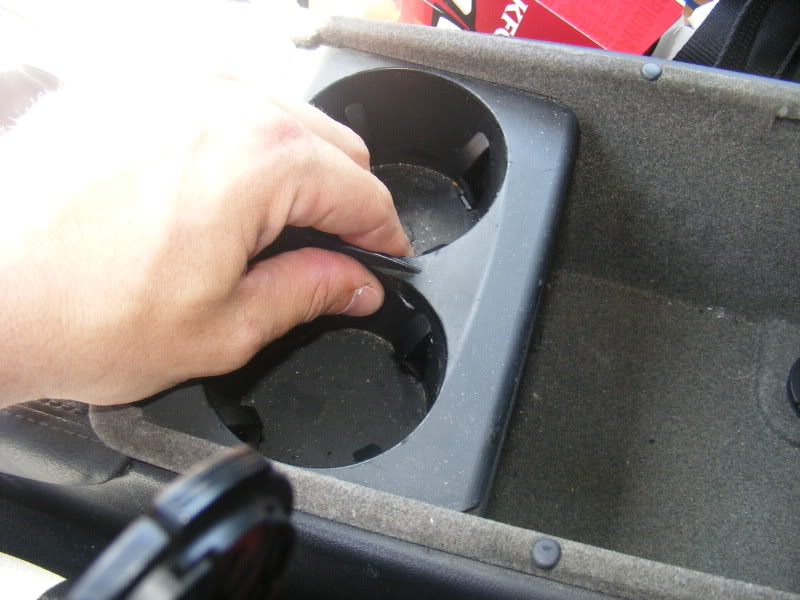
Then open up center console and remove cup holder and fluid catch tray beneath it.
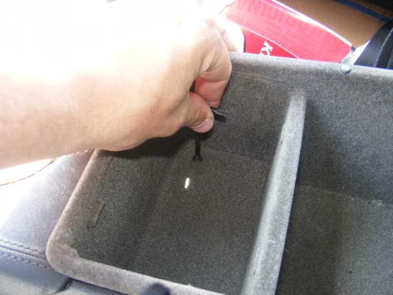
remove two torx screws that hold center console compartment in.
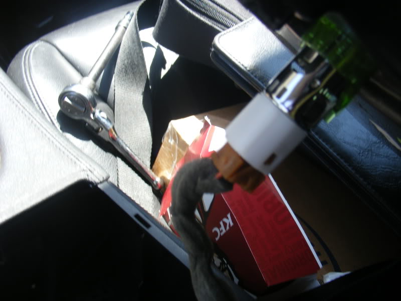
Lift up center console storage compartment and disconnect power outlet (yummmm.... KFC box in the background, less than a week old!)
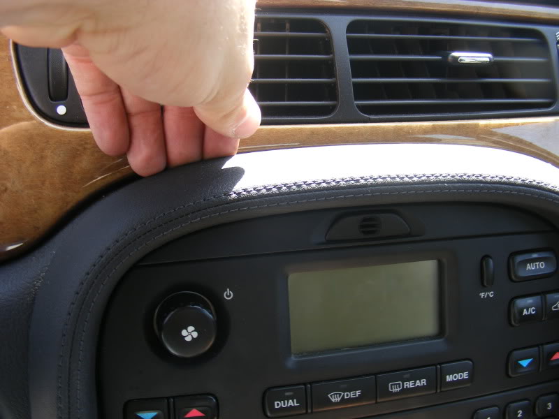
Remove center console trim by first pulling up here
and then pulling back from this point on each side.
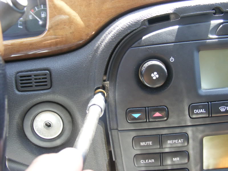
remove 4 bolts holding in climate control and radio
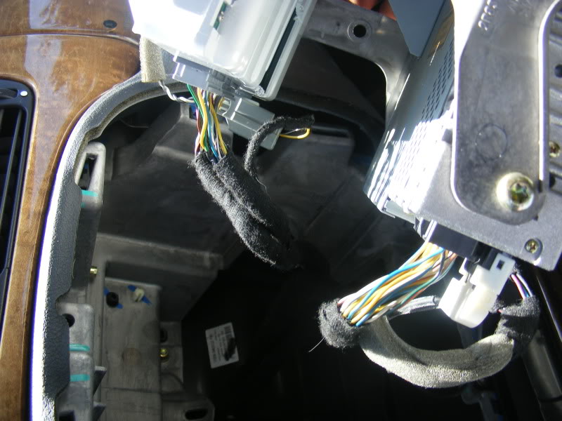
remove the crazy amout of wires going into all the sensors, buttons, radio, and climate control module. The bottoms ones just squeeze and pull they will come out
remove 4 torx screws that hold in climate control module
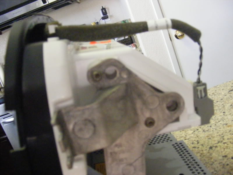
pry off air-bag distance sensor from back of climate control module
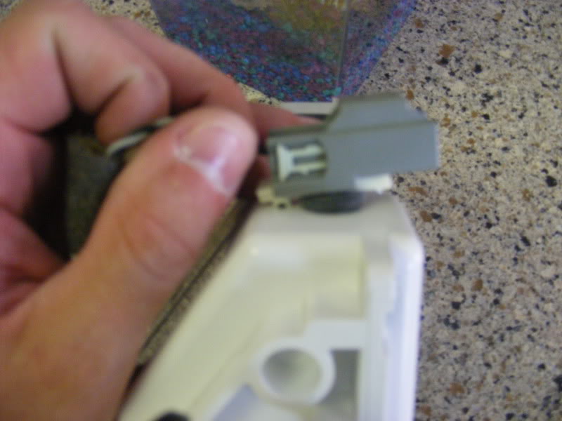
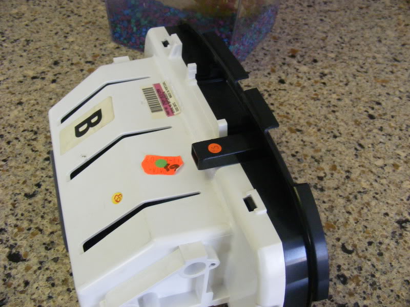
separate back cover from front on climate control module, by pusihing in on the two tabs
pull connector off of back circuit board
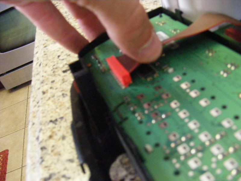
Remove four tiny torx screws to free up circuit board from back piece. (I had to cut a groove in them with a dremel and use a standard). Ignore the hole I cut out of it to get a better view..
Locate your bad trace (or 2 I guess, depending on how bad yours failed).
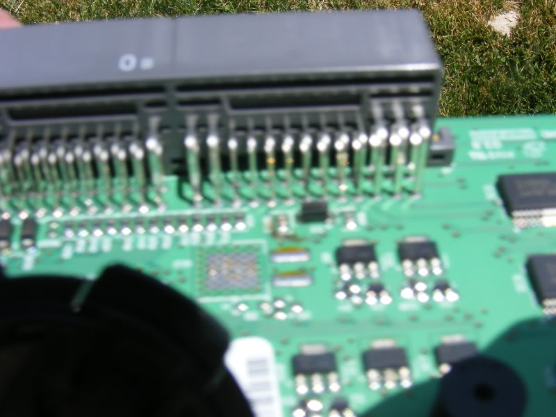
Follow trace from beginning to end, and solder a small wire from the pin going to the board, to the hole where the trace ends. For the pin going into the board, I just made a J with my wire, and hooked it around the pin and soldered it into place... For the other side, I just pushed the wire through, laid a glob of solder on it, then pulled it into the hole while applying heat (gently). I don't really know what I am doing with electronics repair, so there is probably a cleaner way to do it.
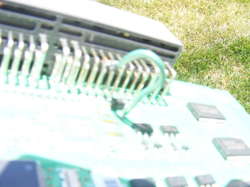
Test with Ohm meter, reassemble, and enjoy your air-conditioning (I know I am, its almost summer in southern california, I've been burning up!).
Thanks to Brutal on this forum for telling me that it can be fixed by a PC repair company (I actually own a network consulting firm). So with that knowledge I figured I would take a stab at it, what's the worst that could happen? Broken climate control module (just buy one on ebay, $150 or so if you can find one...)
Okay, so here are the pics and the steps. may come in handy if you don't have a jtis CD and don't know how to remove the trim because of it (lolrd knows I was worried).
You need to replace your DCCV first, because the board doesn't burn itself out. I noticed that when checking the DCCV when it is unhooked from coolant, it cycles when key is clicked to on position. Just look in the holes and you will see it move. Mine only moved on one side, so my climate control unit was bad.
Tools needed, solder, soldering iron, some small wire, a few torx bits for the center console, and some tiny torx for the climate control circuit board (or just cut a groove in them with a dremel tool like I did, and remove them with a flat-head screwdriver). 8mm socket (I think) to remove the climate control and radio unit from the dash.
First step, remove shifter trim by opening ash tray and pulling up like so.
Then open up center console and remove cup holder and fluid catch tray beneath it.
remove two torx screws that hold center console compartment in.
Lift up center console storage compartment and disconnect power outlet (yummmm.... KFC box in the background, less than a week old!)
Remove center console trim by first pulling up here
and then pulling back from this point on each side.
remove 4 bolts holding in climate control and radio
remove the crazy amout of wires going into all the sensors, buttons, radio, and climate control module. The bottoms ones just squeeze and pull they will come out
remove 4 torx screws that hold in climate control module
pry off air-bag distance sensor from back of climate control module
separate back cover from front on climate control module, by pusihing in on the two tabs
pull connector off of back circuit board
Remove four tiny torx screws to free up circuit board from back piece. (I had to cut a groove in them with a dremel and use a standard). Ignore the hole I cut out of it to get a better view..
Locate your bad trace (or 2 I guess, depending on how bad yours failed).
Follow trace from beginning to end, and solder a small wire from the pin going to the board, to the hole where the trace ends. For the pin going into the board, I just made a J with my wire, and hooked it around the pin and soldered it into place... For the other side, I just pushed the wire through, laid a glob of solder on it, then pulled it into the hole while applying heat (gently). I don't really know what I am doing with electronics repair, so there is probably a cleaner way to do it.
Test with Ohm meter, reassemble, and enjoy your air-conditioning (I know I am, its almost summer in southern california, I've been burning up!).
Last edited by justinb67; 05-09-2010 at 10:01 PM.
The following 10 users liked this post by justinb67:
GT42R (07-04-2012),
Hotshoe (07-25-2013),
joycesjag (02-19-2015),
Jumpin' Jag Flash (07-22-2013),
milespunter (07-21-2013),
and 5 others liked this post.

#3
05-09-2010, 09:50 PM
Justin
The following users liked this post:
Alvin Burns (07-28-2011)
#4
05-10-2010, 08:26 AM

Veteran Member
#5
05-10-2010, 08:38 AM

Veteran Member

#7
05-10-2010, 01:39 PM
Senior Member
Trending Topics
#8
05-11-2010, 07:50 AM
Veteran Member
#9
05-11-2010, 08:12 AM
Veteran Member
#10
07-11-2010, 08:13 AM

Junior Member
Join Date: May 2010
Location: park city
Posts: 26
Likes: 0
Received 0 Likes
on
0 Posts
#11
10-14-2010, 11:07 AM

Member
Join Date: Oct 2010
Location: Thousand Oaks, CA. USA
Posts: 67
Likes: 0
Received 0 Likes
on
0 Posts
#12
10-14-2010, 11:24 AM
Veteran Member
I'll chime in here being an EE.
The easiest way to test the traces, is to set a multi-meter to either continuity beep if your meter has it, or ohms. Touch one side of the meter to the pin, follow the trace, and at the last pad (round thing with a hole you will solder too). It will show continuity if it is good. You will either get a beep, or the ohm reading will get to zero, or very close to zero.
Higher wattage Irons to a point actually help, not hurt the ease of soldering, because they are quickly able to melt solder, and heat up just the piece you are soldering.
30-40 watt irons are perfect for this task.
Should be left to warm up nice and hot - solder should melt instantly when touching the tip.
Also when soldering, you want to touch the solder to the wire or joint you're soldering, not the tip of the iron. You will realize when solder flows. Don't over do the solder, a bit goes a long way.
I'd be happy to resolder one for anyone local if they need help with it.
George
The following 2 users liked this post by androulakis:
Jumpin' Jag Flash (07-22-2013),
StephanWolf (05-09-2011)
#13
05-12-2011, 08:36 PM
Member

#15
05-13-2011, 05:22 AM
Veteran Member
Justin great write up!! Thank you for taking the time to take photos editting them in.
Guys I know I will get flamed here on which soldering irons to use. I personally have 3 different types, a corded pencil style, gun type and my favorite the "cold heat" type that uses 4 AA batteries. By far the cold heat type is my soldering iron of choice on delicate projects like Justins. They work FANTASTIC on circuit boards. If you have you have children you would be amazed at the "broken hair thick wires" used would cause you to throw a $50.00 to $350.00 electronic toy in the dumpster!
I purchased mine long ago through Radio Shack ($20.00), but I see they don't sell them anymore. I looked around and found negative feedback... I don't understand mine has NEVER failed me in many soldering jobs. The only thing I can see is the user(s) must have been using the very thick solder like for plumbing.
The following picture was for an aquaintances lighted steering wheel controls in a 2005 Denali, 4 switches @ dealer $75.00ea. I charged him $135.00 about an hour and a half labor.
The following users liked this post:
Jumpin' Jag Flash (07-22-2013)

#18
07-28-2011, 09:42 PM
I just did this repair and this thread was my source of inspiration and every bit as valuable (if not more) than my torx set or soldering gun.
https://www.jaguarforums.com/forum/s...-thread-58187/
https://www.jaguarforums.com/forum/s...-thread-58187/
#19
09-10-2011, 07:37 PM

Hey, I found a quick fix for this issue. After replacing the DCCV(which was a pain and took about 2hrs with my wife's help), my a/c still was blowing hot/cold. After reading a ton of threads I felt that it was the CCM(Climate Control Module). I removed the module and opened it up(all took about 20mins). I found the burnt trace. I don't know anything about soldering and couldn't find a electronic shop to fix this for me. After looking on youtube I found a video showing a pen that will repair a broken/burnt trace. I purchased it from Radio Shake for $20, its called a Conductive Writer. I followed the directions let it dry for about 45min and prayed it would fix the CCM. I put the CCM back together and hooked it up in the car, powered it up and.... Arctic Air in all vents once again!! I then reassembled everything(car still running), I had to turn the air down before I re-installed the center console liner. I am one happy Jag owner again, come on hot Alabama summer days, we can do battle again.
The following users liked this post:
Jumpin' Jag Flash (02-20-2015)
#20
04-14-2013, 02:59 PM

Junior Member
Join Date: Apr 2013
Location: Durham
Posts: 1
Likes: 0
Received 0 Likes
on
0 Posts
This was very helpful. I replaced DCCV w/ Lincoln part.
Then I took CCM out. I found one very obviously burnt line (see pic). I cleaned it up and tried that radioshack paint stick thing, but that didn't work. Well, it worked for a few minutes. So then I soldered a wire across the 2 points. However, I now only have cold air on the driver's side. The passenger side still blows warm air.
The 2nd pic shows a trace that is very near the connector, partially under the "R86" label. It looks brown-ish. But I can't tell. More importantly, i can't see a point that it leads to or from, except possibly the one I soldered my wire to. Perhaps I burned it when I soldered?
Does anyone know what traces are supposed to lead to where? I've searched all over.
On my CCM, the repaired trace connects (0ohm) to pins 5, 6 & 7 - this does not seem right at all. On the car, 6 & 7 are both black w/ green stripe.