Intake experimenting
#1
 04-14-2009, 04:02 PM


I've done a little experimenting with the intake on my 03 s-type r and here is what I have found so far. Nothing is supported by concrete evidence. Again, this is by my “seat of the pants” meter. I have an odb-II usb scanner with software that can guess hp, 0-60, Ľ mile but I need to wipe ubuntu off my laptop and put xp back on for it to work... which I have not done.
There are 3 areas where I experimented with changing:
2. Mina conical filter & mass air meter housing connected to 3” aluminum tubing up to the oval shaped middle intake piece. My 3" aluminum pipe replaced the mid section plastic tube that runs from the filter box up to the middle of the charge coolers. The factory black plastic pipe has 6 tubes that stick out of it to help quiet down the intake as well as an accordion type section which connects to the mass air meter. On my right angle 3” aluminum pipe, I used a clamp to make one end oval shaped. This made it easier to connect my aluminum pipe to the mid intake piece that runs between the charge coolers. 3” outer diameter pipe is slightly smaller than the factory mass air meter connection and it is smaller than the oval mid intake. 3.5” outer diameter would have actually been better.
Performance Review: Car lost even more torque. Cruising in 2nd gear using j-gate around 3500, punch it and instant torque seems even lower than with the mina intake, but, the power quickly builds afterward. Top end hp felt better than the mina intake alone. It was pretty cool to feel the boost build. Heat soak was horrible. After a few runs, and then idling at a stoplight, the power felt way down.
Sound: friggin wicked. I almost kept the intake like this because of how jacked it sounded.
3. Mid section tube replaced replaced with 3” aluminum tube and factory filter box/mass air meter housing. I was actually surprised at how much better it felt just from replacing the mid section tube. This by far felt like the most increase in hp and torque. Gobs of torque in the mid range punch. Top end felt great as well. I've got a k&n panel filter that is supposed to be at my house tomorrow along with a 2.5-3lb s/c pulley. The existing filter needs to be replaced anyways. I'll see if the filter change helps as well.
Sound was louder than stock. Blips of the throttle equals gulps of air sucked in.
Quality is better than quantity here. The cooler air from the stock over-radiator tube directly into the filter box seems like the way to go. Too much heat is pulled in from an open filter to make a difference. Replacing only the mid section tube seems to have helped the most. I am contemplating building a box to house the conical filter with some additional sources of cool air rammed into it.
There are 3 areas where I experimented with changing:
- Mina intake only
- Mina conical open air filter & mass air meter housing. Mid section plastic tube with silencers replaced with 3” aluminum tube.
- Mid section plastic tube with silencers replaced with 3” aluminum tube. factory filter box and mass air meter
2. Mina conical filter & mass air meter housing connected to 3” aluminum tubing up to the oval shaped middle intake piece. My 3" aluminum pipe replaced the mid section plastic tube that runs from the filter box up to the middle of the charge coolers. The factory black plastic pipe has 6 tubes that stick out of it to help quiet down the intake as well as an accordion type section which connects to the mass air meter. On my right angle 3” aluminum pipe, I used a clamp to make one end oval shaped. This made it easier to connect my aluminum pipe to the mid intake piece that runs between the charge coolers. 3” outer diameter pipe is slightly smaller than the factory mass air meter connection and it is smaller than the oval mid intake. 3.5” outer diameter would have actually been better.
Performance Review: Car lost even more torque. Cruising in 2nd gear using j-gate around 3500, punch it and instant torque seems even lower than with the mina intake, but, the power quickly builds afterward. Top end hp felt better than the mina intake alone. It was pretty cool to feel the boost build. Heat soak was horrible. After a few runs, and then idling at a stoplight, the power felt way down.
Sound: friggin wicked. I almost kept the intake like this because of how jacked it sounded.
3. Mid section tube replaced replaced with 3” aluminum tube and factory filter box/mass air meter housing. I was actually surprised at how much better it felt just from replacing the mid section tube. This by far felt like the most increase in hp and torque. Gobs of torque in the mid range punch. Top end felt great as well. I've got a k&n panel filter that is supposed to be at my house tomorrow along with a 2.5-3lb s/c pulley. The existing filter needs to be replaced anyways. I'll see if the filter change helps as well.
Sound was louder than stock. Blips of the throttle equals gulps of air sucked in.
Quality is better than quantity here. The cooler air from the stock over-radiator tube directly into the filter box seems like the way to go. Too much heat is pulled in from an open filter to make a difference. Replacing only the mid section tube seems to have helped the most. I am contemplating building a box to house the conical filter with some additional sources of cool air rammed into it.
Last edited by blaksplash; 04-15-2009 at 03:39 PM.
#2
04-14-2009, 05:10 PM

Senior Member
blaksplash, excellent write-up! I've been searching for some options on a different intake. The stock intake box works well but the factory mid-section tube has way too many cutouts to muffle sound. I have been wanting to replace that piece with a custom pipe.
How were you able to bend the pipe to fit? And don't forget to update us with how that 2.5-3lb pulley works out for you! I am enjoying my 1.5lb pulley...but you can never have more power...
How were you able to bend the pipe to fit? And don't forget to update us with how that 2.5-3lb pulley works out for you! I am enjoying my 1.5lb pulley...but you can never have more power...
#3
04-15-2009, 02:28 PM
patrick, i was actually reading your post about your pulley yesterday! very good information in there. I hope i won't have to cut my pulley off like they did yours. i will have to trim the snout of the s/c down a little for the pulley to fit. I will probably wait a little while before i put the pulley on there and hopefully get a few runs using the obdII software for a before/after comparison.
i bought a kit off ebay that contained number of different length and angle 3" aluminum tubing designed for a turbo inter-cooler kit. Really anything like this could be used for that section. Just cut each end to fit. To get the one end oval shaped, i put it in a vice to compress it a little so it fit better. The breather hose that comes out of the cam/valve cover - I put a small air filter on it and separated it from the intake.
But today, I was driving and the restricted performance light came on. Guess that will make me fix my laptop so i can pull the code and see whats going on. I changed the intake on friday 4/10... i thought it would have fired off a code quicker
#4
04-15-2009, 03:52 PM
Senior Member
Ah that's the thing I hoped wouldn't happen...the car throwing a code, that is. Hopefully somebody can figure out an efficient design that wouldn't upset the car in any way. Maybe if you routed that small hope from the valve cover to the intake pipe, the car would be happier.
When will you be installing your pulley?
When will you be installing your pulley?
#6
04-16-2009, 08:55 PM
Ah that's the thing I hoped wouldn't happen...the car throwing a code, that is. Hopefully somebody can figure out an efficient design that wouldn't upset the car in any way. Maybe if you routed that small hope from the valve cover to the intake pipe, the car would be happier.
When will you be installing your pulley?
When will you be installing your pulley?
-----------------------
Well last night i ended putting xp back on my laptop. I installed the obdII software and pulled the code- P1111 Intake Air Temperature Sensor Circuit Intermittent High Voltage. I've seen where just cleaning your MAF sensor will sometimes cause this to fire. I'll monitor to see if it comes back. I cleared the code and commenced doing a series of tests using the obdII scanner...
The test consisted of
(a) cruising for a couple miles in second gear at around 35-40mph
(b) stopping and idling for about 40 seconds
(c) then cruising in 2nd for about 45 seconds at 30mph
(d) hammering 2nd gear from 30mph till it hit the rev limiter.
The engine was properly warmed prior to the begging of each test
Ambient air temp during all test: 61deg F
here are the results...
test 1: completely stock intake. stock mid pipe, stock filter box, stock panel filter
(a) intake air temp: ~68 deg F
(b) intake air temp: ~79 deg F
(c) intake air temp: ~71 def F
(d) intake air temp: ~68 deg F, air flow rate from MAF sensor ~43.5 lb/min
test 2: 3" aluminum mid pipe and open air conical k&n filter
(a) intake air temp: ~74 deg F
(b) intake air temp: ~149 deg F
(c) intake air temp: ~111 def F
(d) intake air temp: ~83 deg F, air flow rate from MAF sensor ~50 lb/min
test 3: 3" aluminum mid pipe and stock filter box, k&n panel filter
(a) intake air temp: ~67 deg F
(b) intake air temp: ~78 deg F
(c) intake air temp: ~71 def F
(d) intake air temp: ~67 deg F, air flow rate from MAF sensor ~48 lb/min
I would imagine that if the 3" pipe was replaced with a 3.5" pipe for test 2 & 3, the results would be even better. I saved screenshots of the tests.
As a reference,
(b) is ~170-110
(d) is roughly at -60.
P.S. am i really hitting around 14psi of boost?
Last edited by blaksplash; 04-16-2009 at 10:28 PM.
#7
04-16-2009, 10:54 PM
My hat is off to you blaksplash... this is a very detailed and comprehensive post.. I will definitely be looking for great things from you in the future. As soon as I get my Duster back on the road I am going to start experimenting with the Jag again. Mine is dying for a pulley and I'm assuming yours is going to be needing a less restrictive exhaust soon as well. Thanks again, this is definitely the next modification I am going to do, but I might try to retain the same location for the factory breather on the upper intake tube..
Trending Topics
#8
04-17-2009, 02:26 AM
Veteran Member
Good stuff, to measure is to know is my motto.
Just an additional note, the MAF sensor is very sensitive, and will give different readings when the tube it sits in is only slightly different, I already got different readings when just cleaning the tube… On the danger side it could measure less air, causing a lean mixture. Just to say that the max airflow measured cannot be used as a base to see which air intake will flow more, unless of course you use the same airflow meter part. Of course a leaner mixture might give again some horses, but imho do not play with this unless you actually measure the mixture on a dyno to ensure you are within the safe regions.
With your second test; if for example the MAF would read more air it would mean a rich mixture. That in combination with the higher intake temps, which will cause the ECU to even retard the ignition and increase the mixture, would explain the power loss. But just the hotter air is enough to drastically reduce power; this is a classical problem for supercharged systems (especially roots systems) with an air to water cooling system.
I hope people will take here notice of your 2nd test, the Open filter & temperature thing.
Another tip, you can get more readings per second (so more accurate picture) from a standard obdii meter if you select fewer sensors to measure. The ECU will only provide a couple of values per second, so the fewer sensors you select, the more readings you get for the other sensors. Usually I always select the engine RPM, and then the parameter I would like to check for instance just the MAF, or just the ignition. Also even better would be to use 3rd gear as it takes longer so you get even more readings, unfortunately you will also go a bit quicker…
Andre.
Last edited by avos; 04-18-2009 at 02:15 AM. Reason: Typo
The following users liked this post:
zetecstr101 (04-16-2012)
#9
04-17-2009, 02:34 PM
My hat is off to you blaksplash... this is a very detailed and comprehensive post.. I will definitely be looking for great things from you in the future. As soon as I get my Duster back on the road I am going to start experimenting with the Jag again. Mine is dying for a pulley and I'm assuming yours is going to be needing a less restrictive exhaust soon as well. Thanks again, this is definitely the next modification I am going to do, but I might try to retain the same location for the factory breather on the upper intake tube..
I do plan on moving the breather to the new aluminum pipe. I haven't done it yet because i didn't want to put too much time into it if there was no real improvement.
Good stuff, to measure is to know is my motto.
Just an additional note, the MAF sensor is very sensitive, and will give different readings when the tube it sits in is only slightly different, I already got different readings when just cleaning the tube… On the danger side it could measure less air, causing a lean mixture. Just to say that the max airflow measured cannot be used as a base to see which air intake will flow more, unless of course you use the same airflow meter part. Of course a leaner mixture might give again some horses, but imho do not play with this unless you actually measure the mixture on a dyno to ensure you are within the safe regions.
With your second test; if for example the MAF would read more air it would mean a right mixture. That in combination with the higher intake temps, which will cause the ECU to even retard the ignition and increase the mixture, would explain the power loss. But just the hotter air is enough to drastically reduce power; this is a classical problem for supercharged systems (especially roots systems) with an air to water cooling system.
I hope people will take here notice of your 2nd test, the Open filter & temperature thing.
Another tip, you can get more readings per second (so more accurate picture) from a standard obdii meter if you select fewer sensors to measure. The ECU will only provide a couple of values per second, so the fewer sensors you select, the more readings you get for the other sensors. Usually I always select the engine RPM, and then the parameter I would like to check for instance just the MAF, or just the ignition. Also even better would be to use 3rd gear as it takes longer so you get even more readings, unfortunately you will also go a bit quicker…
Andre.
I might do a few more test runs with the current setup with the scanner to get more detail measurement as you described. I tried to do the HP dyno tests with the software, but it kept saying it had around 2700hp...
What is the best way to launch these things? I get a lot of 1-wheel spin. MY best 0-60 out of 3 tries was 5.3... and that was with traction control on and the 60' was 2.38
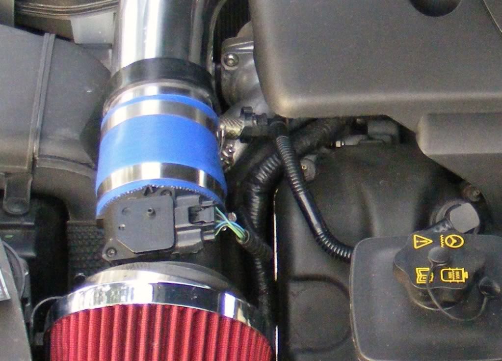
attached is a quick camera phone pic of the intake
Last edited by blaksplash; 04-17-2009 at 03:23 PM.
#10
04-17-2009, 04:57 PM
Hi Backlash,
Awsome write up mate, i'm very intersted in this mod as would like a little more induction noise and increased air flow but was dubious about the minagallery kits due to all the engine bay hot air being sucked in!!!
Did you also order the silicone tube from E-bay or is that just used from the mina kit?? also how have you attached the silicone tube to the supercharger end? and the most important question............any more warning lights?
Cheers,
Damien
Awsome write up mate
, i'm very intersted in this mod as would like a little more induction noise and increased air flow but was dubious about the minagallery kits due to all the engine bay hot air being sucked in!!!Did you also order the silicone tube from E-bay or is that just used from the mina kit?? also how have you attached the silicone tube to the supercharger end? and the most important question............any more warning lights?
Cheers,
Damien
#11
04-17-2009, 05:58 PM
Hi Backlash,
Awsome write up mate, i'm very intersted in this mod as would like a little more induction noise and increased air flow but was dubious about the minagallery kits due to all the engine bay hot air being sucked in!!!
Did you also order the silicone tube from E-bay or is that just used from the mina kit?? also how have you attached the silicone tube to the supercharger end? and the most important question............any more warning lights?
Cheers,
Damien
Awsome write up mate
, i'm very intersted in this mod as would like a little more induction noise and increased air flow but was dubious about the minagallery kits due to all the engine bay hot air being sucked in!!!Did you also order the silicone tube from E-bay or is that just used from the mina kit?? also how have you attached the silicone tube to the supercharger end? and the most important question............any more warning lights?
Cheers,
Damien
and so far no warning lights... but i will definitely let you know if it returns
for those of you who would like to see the stock tube that was replaced, i've attached pic of it - notice all 6 silencing tubes and many cavities. also attached is a pic of the mina intake kit - the aluminum tube is the MAF sensor tube, the heat shield is in there as well.
Last edited by blaksplash; 04-17-2009 at 07:23 PM.
#12
04-18-2009, 02:14 AM
Veteran Member
"With your second test; if for example the MAF would read more air it would mean a right mixture. "
That should have read of course "rich mixture" not right.
If indeed as you say the pipe was smaller, the MAF sensor would measure more air comming thru that actually is, so a very rich mixture, and combined with the hot air noticable hp loss as you have fealt.
Andre.
That should have read of course "rich mixture" not right.
If indeed as you say the pipe was smaller, the MAF sensor would measure more air comming thru that actually is, so a very rich mixture, and combined with the hot air noticable hp loss as you have fealt.
Andre.
#14
04-18-2009, 09:14 PM
"With your second test; if for example the MAF would read more air it would mean a right mixture. "
That should have read of course "rich mixture" not right.
If indeed as you say the pipe was smaller, the MAF sensor would measure more air comming thru that actually is, so a very rich mixture, and combined with the hot air noticable hp loss as you have fealt.
Andre.
That should have read of course "rich mixture" not right.
If indeed as you say the pipe was smaller, the MAF sensor would measure more air comming thru that actually is, so a very rich mixture, and combined with the hot air noticable hp loss as you have fealt.
Andre.
and today it threw some codes- p0171 & p0174. I'll try cleaning the MAF sensor and see if that helps. Also, anyone got a good idea how to plumb the breather hose to the aluminum tube?
#15
04-19-2009, 03:55 AM
Veteran Member
"so if i understand you correctly, test 2 might not have really had the best flow. The MAF may have thought it had more air than it actually did."
Yes indeed.
"and today it threw some codes- p0171 & p0174. I'll try cleaning the MAF sensor and see if that helps. Also, anyone got a good idea how to plumb the breather hose to the aluminum tube? "
If you haven't connected the tube, the engine will suck false air in, so most likely the case of the P0171/P0174, which are lean codes.
You must connect this breather tube to the intake; otherwise you could get an imbalance in engine over/under pressure. Ask an aluminum welder to fit a similar connection fitting to weld to your intake tube; any professional welder can do this for a fair price. Then connect the original tube to that.
Andre.
#16
04-19-2009, 05:34 AM
#17
04-20-2009, 09:45 AM
While i work on getting the breather hose on my aluminum pipe, i put the stock tube back on. I realized that I never did a run with the stock filter box and stock pipe with the k&n panel filter.
So, here is a graph of the stock box/pipe with the k&n filter, and also another graph of the stock box with k&n filter and aluminum pipe. This time there is a bit more detail... but i should have graphed RPM as well. Just by adding the k&n filter allowed it to hit a much higher flow than the stock panel filter, which hit ~43.5 in the other test... or maybe my paper filter was just that dirty?

Low-mid range has much better airflow, and max flow at the top is sustained longer.
Last edited by blaksplash; 04-20-2009 at 09:53 AM.
#18
04-20-2009, 04:50 PM

Member
Join Date: May 2008
Location: Toronto
Posts: 92
Likes: 0
Received 0 Likes
on
0 Posts
#19
04-20-2009, 04:57 PM
Senior Member
Very interesting thread. What software and reader do you use to pull out these numbers, blaksplash? It would definitely be helpful for me, and I assume many other people, if we could know what you are using so that we can all monitor our numbers.
I wonder if my car will read that it is taking in a little more air as I have a pulley. Your car has the factory pulley correct?
I wonder if my car will read that it is taking in a little more air as I have a pulley. Your car has the factory pulley correct?
#20
04-22-2009, 10:33 AM
"and today it threw some codes- p0171 & p0174. I'll try cleaning the MAF sensor and see if that helps. Also, anyone got a good idea how to plumb the breather hose to the aluminum tube? "
If you haven't connected the tube, the engine will suck false air in, so most likely the case of the P0171/P0174, which are lean codes.
You must connect this breather tube to the intake; otherwise you could get an imbalance in engine over/under pressure. Ask an aluminum welder to fit a similar connection fitting to weld to your intake tube; any professional welder can do this for a fair price. Then connect the original tube to that.
Andre.
Andre is correct. I purchased my intake tube from a shop that welded the connection for the breather tube. No codes after install.