When you click on links to various merchants on this site and make a purchase, this can result in this site earning a commission. Affiliate programs and affiliations include, but are not limited to, the eBay Partner Network.
No chimes, dings or buzzes on my 06 STR. Fixed. Also found major manufacturing defect
Sometime soon after I got my 06 STR I realized my front parking aid wasn’t working. Also I dont believe i ever had any tones or noises for the key in buzzer or any warnings chimes.
Some quick troubleshooting at the time showed that I had the signal for the front parking aid at the connector that’s behind the side panel on the left side of the dash pad so I figured the problem was with the actual speaker In the instrument panel. I figured the speaker must’ve gone bad or I had a open connection somewhere.
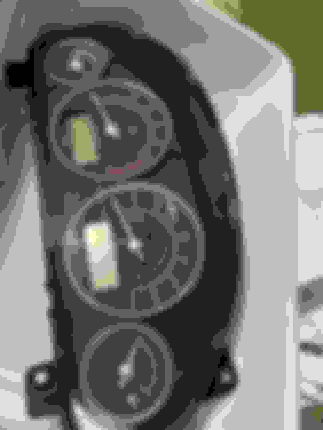
not wanting to break any trim pieces or tackle removing the instrument panel I let it sit for a while. that’ll changed last night when I got some encouragement from some other forum members who had removed the panel who claimed it was quite easy to remove the instrument panwl. They were right! It was pretty easy!
So I got the instrument panel out of the car and I verified that I had continuity from the parking aid modual all the way to the connector at the back of the instrument panel and I had a good ground at the instrument panel so the fault must have been in the speaker as I suspected
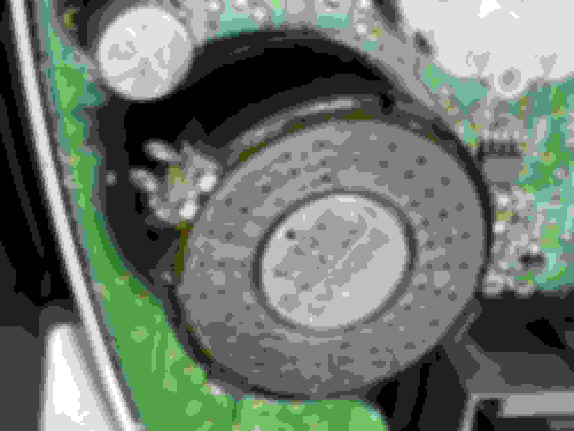
The speaker mounts the back of the instrument panel circuit board and is held in place with a small plastic structure that is supposed to keep it from wobbling around but it does not do a very good job. I noticed that my speaker was still mounted to the back of the instrument panel but it could move quite a bit even though it appeared to be soldered in place
I had no continuity between the exposed terminals on the speaker to the circuit traces on the circuitboard on the instrument panel so that pretty much pointed to some broken solder joints. Unfortunately that black plastic mounting structure that holds the speaker in place covers up the solder joints and I didn’t want to try to see if the circuit board can come completely off the back of the Instrument panel because I was afraid of breaking something in the process so I basically cut a small access slot in that plastic mounting piece that holds the speaker down so I could get to the speaker connections at the circuit board to check for cracked solder joints
After making a little access hole I could see the solder joints were both cracked using a magnifying loop and I will solder it back into place. I’ll probably add some JB Weld to the back of it to make sure it doesn’t vibrate into another cracked solder joint.
Since I had the Instrument panel off, I decided to do a detailed visual inspection of all the other components to make sure nothing else had a cracked solder joints.
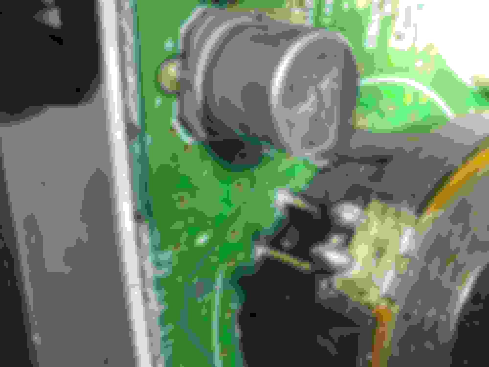
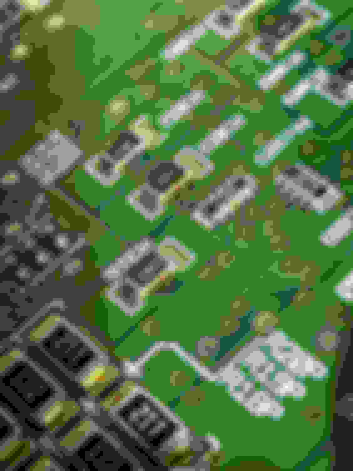
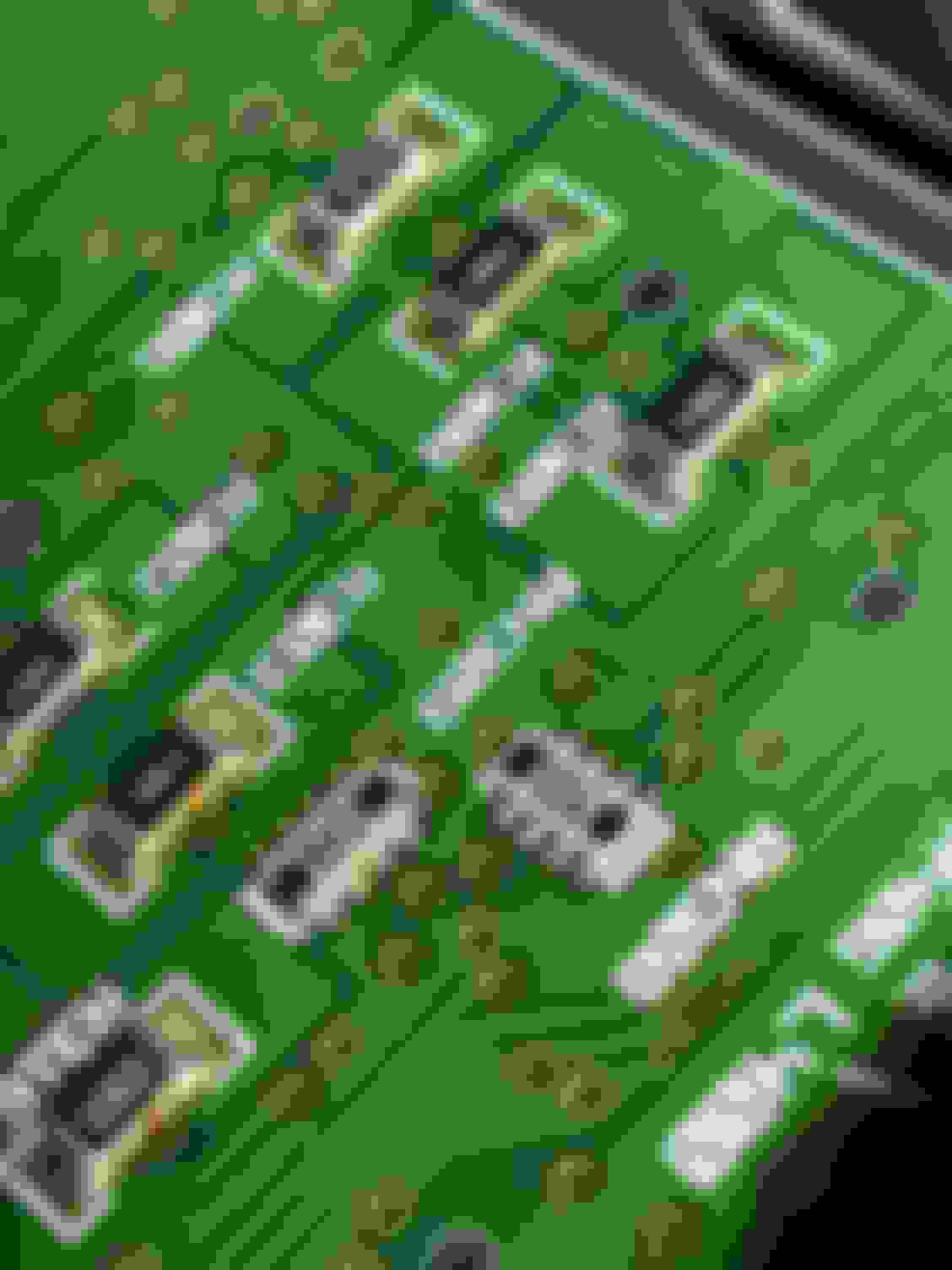
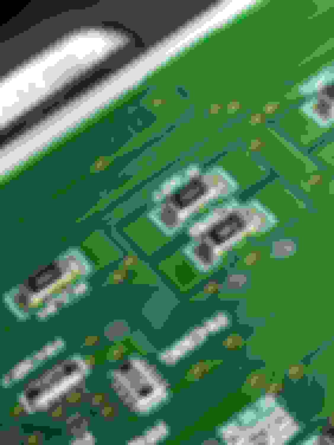
I’m glad I did because I noticed a major latent defect with the board That is probably on many other instrument panel circuit boards- There were tons of little solder ***** along the sides of most of the surface mount resistors on the board. The solder ***** were pretty well adhered due to the residual flux that was still on the board but many of the solder ***** Looks like they bridged between two conductors and could have caused shorts if it wasn’t for the solder mask that’s used to insulate the copper traces on the circuitboard. I used a very short pair of tweezers to pick the soda ***** off the circuitboard but it makes me Wonder one of the solder ***** was Causing and intermittent short. I would get random periodic can bus faults from time to time And well I’ve done several things to try to make it go away it keeps coming back now and then
so
I haven’t yet resoldered the speaker back onto the board but I’m pretty sure that that will cure my problem.
Here are just a couple of the pictures I took of the solder ***** i had.
but there were a couple dozen of them in total.
I found solder ***** on almost every surface mount resistor on the board. Some look like they had made contact to the solder joints at the ends of the resistors and quite a few bridged across circuit board traces. This can shorts and reap havoc on the electrical system. It’s definitely a **** poor manufacturing process. Looks like they don’t have a very well organized workmanship inspection on these during assembly. (If any).
here are some examples of the latent defects I found.
No wonder there are occasionally electrical issues, which are kind of impossible to explain....
One can only hope that those extra solder-***** are encased in non-conductive flux and glued into position that way.
Btw.: I am always overly cautious when soldering on any kind of PCB: I let the soldering iron heat up, clean the tip, but a bit of solder on it, and then - before any contact with the PCB - I switch the soldering iron off, because I am kind of afraid that some overlaying sparks from the grid could jump over to the tip of the soldering iron and cause damage to those highly sensitive ICs...
PS: I know it from the past (last millennium) that the supplier of the instruments would print its name on the instruments, like "VDO", but that dodgy job above does not look like something VDO would do, and apparently the supplier does not dare to put its name to it - not even on the backside on the PCB...
Last edited by Peter_of_Australia; 07-15-2023 at 06:10 AM.
This looks worse than Italian electrics from the mid 1980s to late 1990s.
I had my instrument cluster out to fix the speedo which had a slipping clutch on the drive. There's a place in the Detroit area that does all of these, a benefit of the Ford ownership.
I never had any of these intermittent error messages but then my car never got this old or had this many miles on it. BTW, it looks like it's going to the wreckers soon. I think I've lost my mechanic. I think the job is much bigger and potentially problem fraught than he'd hoped.
One of my friends here in Essex UK, used to work for the company that made the clusters for Jaguar.
I think this was Visteon in Chelmsford Essex.
He was involved with testing and fault finding the clusters, I will mention this to him when I see him next.
Mellow
Last edited by M-e-l-l-o-w; 07-21-2023 at 03:42 AM.
One of my friends here in Essex UK, used to work for the company that made the clusters for Jaguar.
I think this was Visteon in Chelmsford Essex.
He was involved with testing and fault finding the clusters, I will mention this to him when I see him next.
Mellow
well the resoldering job did not fix the problem. Still nothing (no sounds) from the speaker in the IP.
I have a spare IP from my parts car but its just a regular IP from a 4.2l NA (not supercharged) and I wasnt real excited with the thought of the module configuration chaos that awaits ne if I tried swapping in a used IP module.
ask your buddy if theres any way to get his hands on a schematic for the circuit board. Maybe I can find another bad solder joint. I did spend a long time-at least an hour inspecting this board using a high power magnifying loupe but besides the possible broken solder joints at the speaker and the solder *****, I couldnt find any other obvious issues. No signs of overheated parts no burnt traces and no puffed up caps.
it is interesting to note that after I reinstalled the original cluster I had several module communication faults when I went back in the SDD. So I re-examined the data link connector and looked at all the wiring harnesses that I had messed with prior to removing the cluster and I thought to doing some continuity checks on the bus lines. Prior to messing with this cluster issue I had replaced the data link connector under the instrument panel because I noticed I was having some troubles with SDD. On my Continuity checks did not show any obvious broken wires but many of the connector sockets that were in the data link connector (female contacts) as well as some connector sockets in the front electronics module connectors felt loose like they had lost some of their spring contact force. I spent a lot of time unpinning those connectors and readjusting the wipers in each socket to restore the contact forces and that seemed to solve the communication errors.
for those that dont know, the terminal sockets used in both the DLC and the FET (front electronics modules) as well as many other connectors in our cars use female sockets as shown in the pic below. Inside the opened end of these female sockets there is a thin strip of tin plated copper that is bent over and runs along the inside cavity of the socket that acts as a wiper and makes electrical contact with the male meeting pin. This wiper works great to make electrical contact when the connectors are first mated together. but if you’ve ever disconnected and reconnected a connector, especially more than once or twice (like when you’re hooking up to that data link connector to check for codes or during troubleshooting), that wiper tends to get pushed back away from the mating pin so you can lose electrical contact. So I spent hours twisting my body to get under the dash to remove each pin one by one and using a tiny jewelers screwdriver to try and get under each wiper in each socket to bend it back into position where electrical contact is restored.
I also noticed the green and yellow twisted wire pairs for the SCP bus going into the FET had an abnormally long section where the wires werent twisted right as they go into the connector housing at the FET. So I twisted them before I put those pins back into their slots at the connector housing and it seemed to fix the communication error.
those bus wires seem very sensitive to electrical noise and ive found that poor connections and having too much untwisted length on the bus wires cause data communication errors so its kind of routine for me to rebend wipers, retwist twisted pairs and clean off any oxidation from the terminals.


 07-15-2023, 05:34 AM