When you click on links to various merchants on this site and make a purchase, this can result in this site earning a commission. Affiliate programs and affiliations include, but are not limited to, the eBay Partner Network.
It came time for me to change the front shock absorbers on my car, which incidentally has CATS suspension. I duly ordered the new shockies ($$$$) and then started doing my research on how to do the change-out. The manual talks about using Jaguar compression tool number 204-476 (see below) so out of curiosity I priced one. From what I could find there were none available anywhere, but I did find a price if one happened to become available – USD1650 plus delivery to Australia.
The Bilsteins had already pretty much emptied my bank account, so there was no way I was going to buy the real tool, even if I could find one. Hence I thought it was back to a pair of auto-shop spring compressors for me. The first pair I tried wouldn’t fit between the turns of the spring, so I bought another pair which did fit between the coils, but they were fouling on the shockie. It took me about five seconds to decide I valued my limbs/life too much to persist, so I put on the old thinking cap. The following was what I came up with.
I noticed that the centre section of a set of front disk rotors which I had recently changed would nicely enclose the upper mounting plate, and all I would need to do would be to drill two holes to accommodate two of the mounting studs; the other pair fitting in one of the original wheel stud holes.
The next step was to cut a slot in a second rotor to allow the lower end of the shock absorber to go through its centre. I worked out that this slot would still allow the lower spring seat to be fully supported.
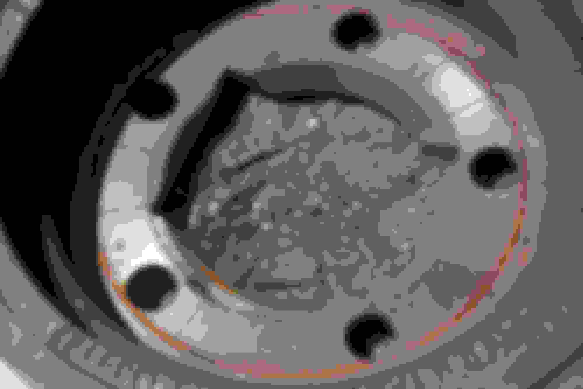
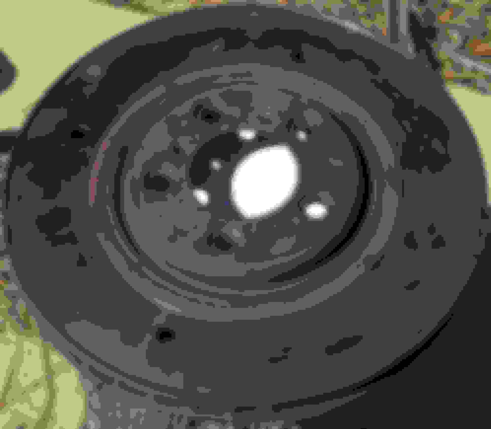
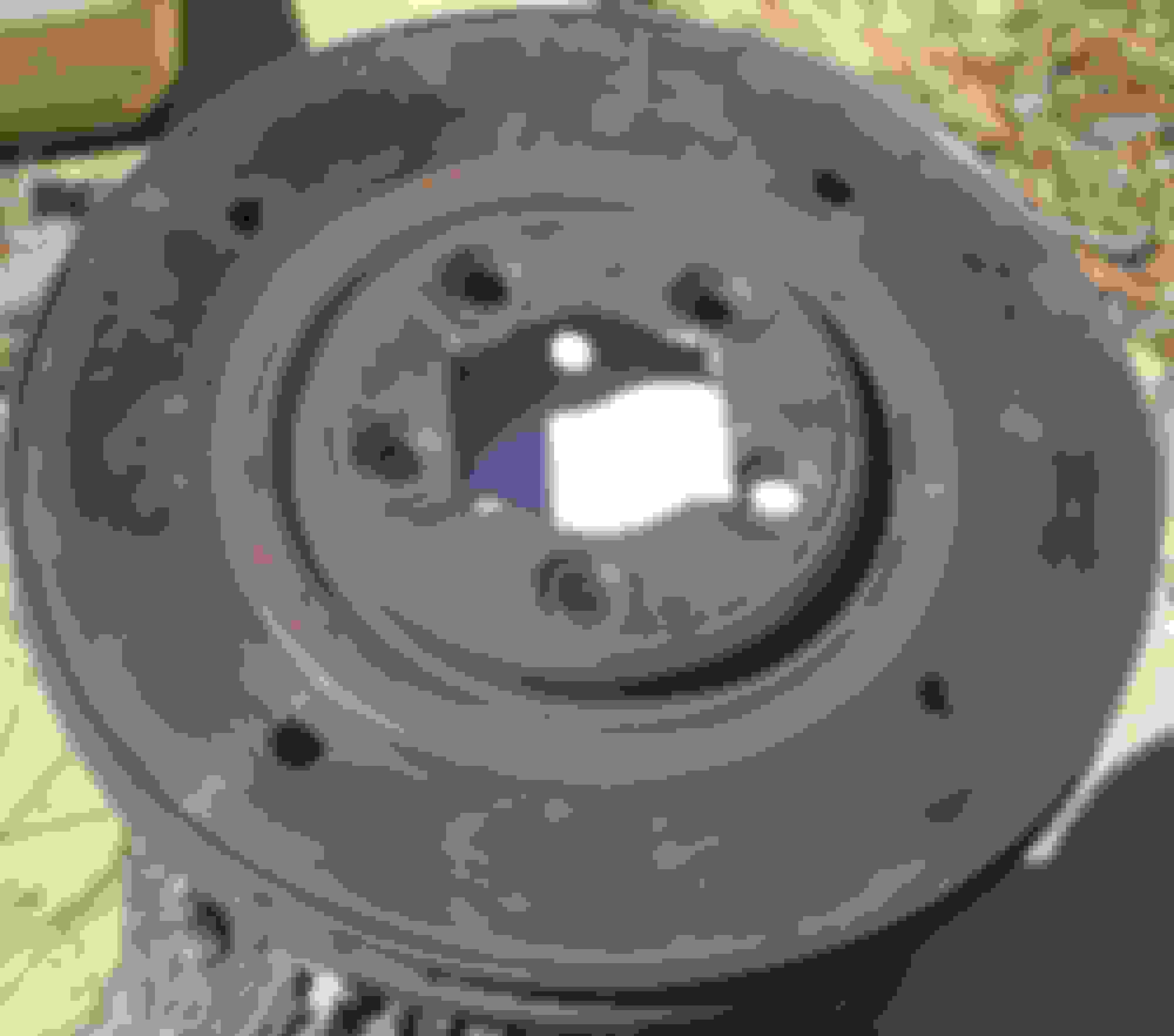
Now that I had the top and bottom plates for my spring compressor, I had to come up with the actual means of compressing them. I decided to use four, eighteen inch long threaded rods, half of an inch in diameter. The rods are arranged in a square, 170mm on the side (sorry about the mixed units). This necessitated me drilling 9/16 inch holes in the rotors. The main challenge was to very carefully orient the square so that it missed the fins in the middle of the rotor. I almost succeeded, as can be seen in the photos below!
Top Plate Bottom Plate
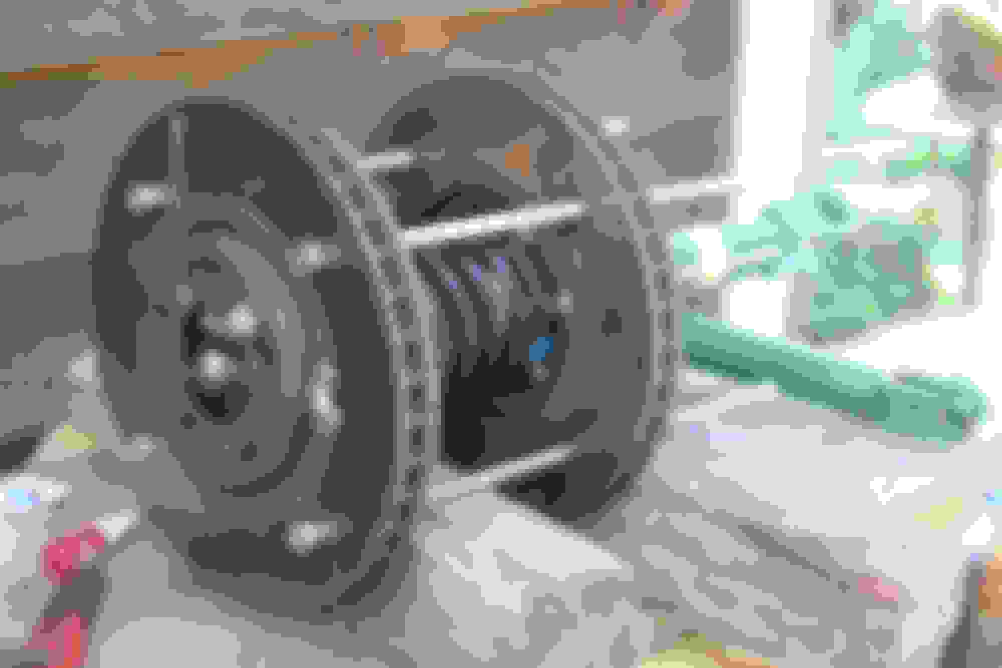
Now that the basic elements of my jig were in place, this is how I used it. I secured the rods to the ‘top plate’ using nuts either side of the rotor. I then secured the spring and old shockie to the top plate using two of the upper mounting studs. I turned the whole thing upside down and then put the second rotor in place. A washer and a nut was used on each of the rods and they were lubricated with oil. This is what it looked like (its actually the new shock absorber but, except it is clean, in a photograph it looks the same whether the old shock absorber is coming off or a new one going in):
Completed Jig
At first I very laboriously tightened the four rods in rotation, measuring the distance between the rotors as I compressed the spring. I fairly quickly learnt that this jig worked so well that I only needed to pull down on two of the rods, on opposite sides, while the other two rods effectively acted as ‘dowels’. So the sequence became: spanner tighten rods One and Three approximately 3-5 mm, and then finger tighten rods Two and Four, as an insurance policy.
Once the spring had been sufficiently compressed that the tension had been taken off the top nut of the old shock absorber, the jig was tipped on its side, top nut removed and then the tension taken off the spring so that the shock absorber could be safely removed.
8mm allen key, 17mm spanner
I had one other little problem that I had to overcome. The torque on the top nut of a CATS shock absorber is 20 foot pound. Unfortunately my torque wrench is a very conventional, half-inch socket drive. I had to come up with some way of securing the centre shaft of the shock absorber, which uses an 8mm allen key, while simultaneously measuring the torque I was applying to the nut. Fortuitously I own a set of through-drive sockets, so I made the following adaptor:
3mm plate
This let me engage my torque wrench to the pass-through socket, while simultaneously using the allen key as shown below. If you do the trigonometry, with my torque wrench oriented the way I had it, the error caused by the offset is almost negligible – certainly the error in my torque wrench would be greater.
I have to say that, in contrast to my sense of unease (terror?) whenever I have used conventional coil spring compressors in the past, using this jig I felt that I was at all times in control of the situation, feeling completely safe throughout the operation.
And in case you are wondering - the difference to the car's ride and handling is remarkable!
Last edited by roger.neill; 03-10-2020 at 08:10 AM.
One small favor to request. I'm not familiar with how the end of the shock/spring assembly fits into the rectangular opening you cut into the brake disc. Can you please post a pic of the end of the shock/spring assembly?
If one didn't have a scrap pair of brake discs handy, could this tool be fabricated from something like 1/4" plate steel?
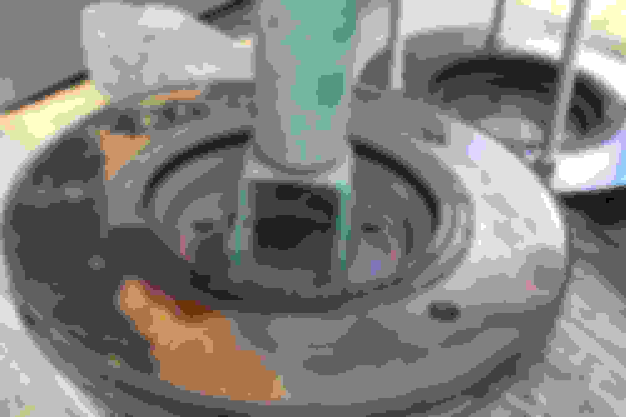
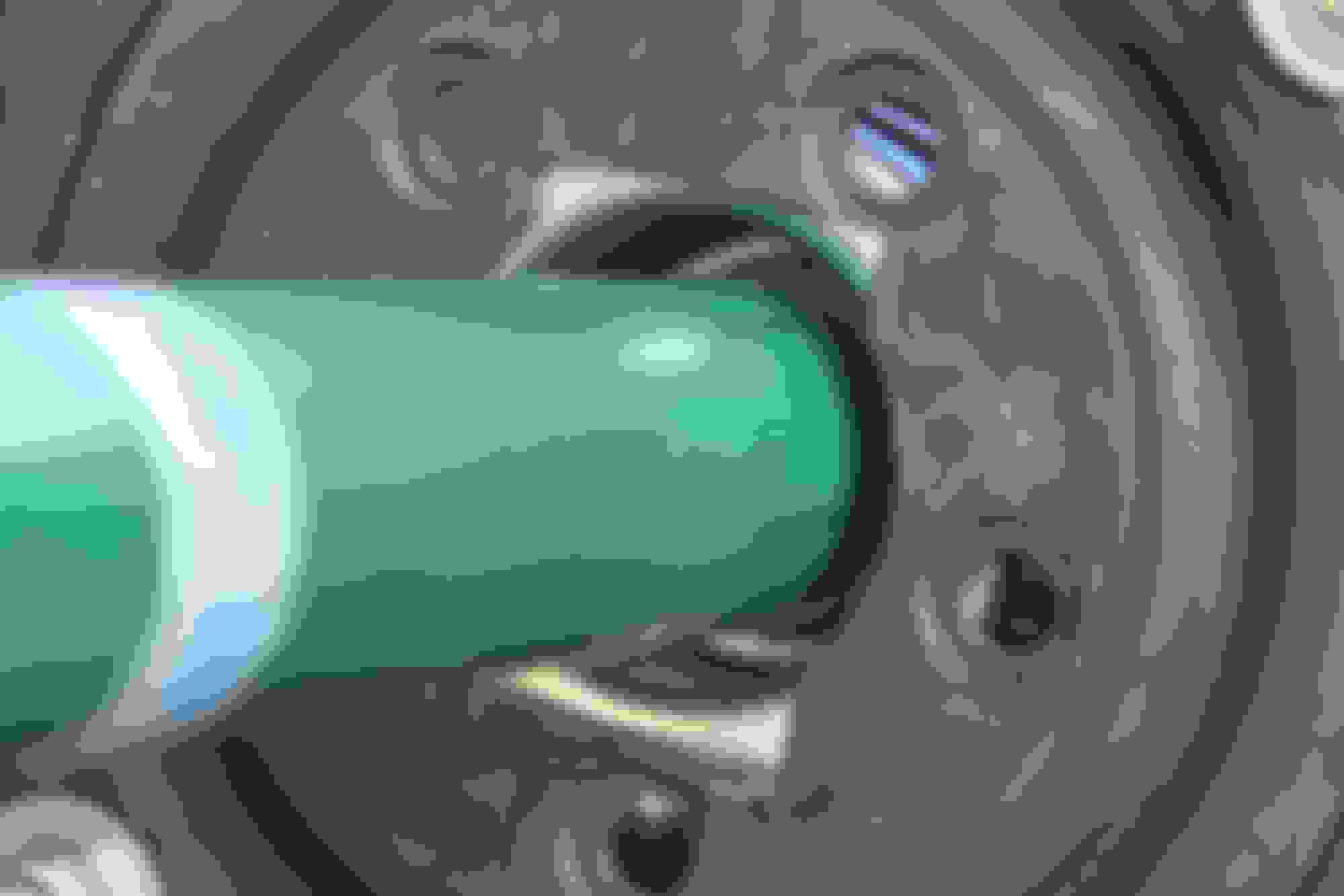
The rectangular cutout simply allows the disk to be slipped over the end of the shock. It doesn't serve any other purpose. Sliding shockie through the slot
These are views from both sides of the plate once it is seated on the spring:
Regarding you question about the use of quarter inch plate - I am a scientist not an engineer, so I tend to overdo design to make sure. I am also a bit of a bush mechanic so take the following for what it is worth: if I were to use plate I would bring the rods in from 170 mm between centres to, say, 140 mm between centres. That should minimise the chance of the plate distorting.
I think I was doomed to be bush mechanic - after all I live in a town called Woodend. Rather fitting that here is a picture of my chassis stand
The rectangular cutout simply allows the disk to be slipped over the end of the shock. It doesn't serve any other purpose.
Uff da! I hadn't thought of that. My brain clutch must have been slipping.
Originally Posted by roger.neill
if I were to use plate I would bring the rods in from 170 mm between centres to, say, 140 mm between centres. That should minimise the chance of the plate distorting.
You've answered my next question before I even had a chance to ask. It looked the spacing you used was based on drilling through the middle of the flat surface of the brake rotors. I had been wondering if one could tighten up that dimension if working with a blank slate, i.e. a flat piece of heavy plate steel.

 03-10-2020, 08:03 AM