When you click on links to various merchants on this site and make a purchase, this can result in this site earning a commission. Affiliate programs and affiliations include, but are not limited to, the eBay Partner Network.
Specifically this picture, showing how the valve can be disassembled:
From what I understand, you can remove 6 fasteners and then lift the solenoid coils and valves from the main housing. Has anybody ever tried replacing any bad parts this way, without removing the entire valve assembly? Inquiring minds want to know...
Well, none of you cotton-headed ninny muggins stepped up, so I had to answer my own question.
As previously mentioned, the Dual Climate Control Valve (DCCV) started acting up on my �02 V6. I was only getting moderate heat on the driver�s side. The passenger�s side was nice and toasty, but not so much for me behind the wheel. The valve seemed to close properly when cooling was commanded. When heat was requested, one side of the valve wasn�t letting enough hot coolant reach the heater core. You can read plenty more about the DCCV and the rest of the heating/cooling system in this troubleshooting guide:
Post #2 in the guide details two methods to make sure the valve closes properly, something very important for proper AC operation. However, I never considered the valve failing to open fully when heat was commanded. In my case, only one side was misbehaving. This was easy to confirm by increasing the selected temperature until HI was displayed. This puts the system in manual mode, and bypasses most (but not all) automatic inputs. I selected the dash vents because it�s an easy spot to measure the temperature, and sure enough, my handy pocket thermometer showed the driver�s side was about 20F cooler.
It was time for a new DCCV, which is a real pain to replace. I had replaced this unit about 10 years ago, and remember it was a miserable experience. Courtesy of Gus, here's a good write-up of a DCCV replacement. For an easier installation, be sure to notch the mounting flange as he has suggested.
If you replace the DCCV, repeat either test from the troubleshooting guide. The DCCV has a very high failure rate and there's no guarantee a new one will be good.
Now I�m lazy, and proud of it. I put on my orthopedic thinking cap and got to wondering if there was a better way. Did I really have to replace the entire valve assembly, and deal with those inaccessible hose connections? Or could I leave the body and hoses untouched, and simply replace the two individual valves? Well, happy day! It turns out it was quite easy to do. This lazy man�s shortcut busted a lousy job down to size. Please note these details are specific to the DCCV found on the early (�99-�02) S-Type. I don�t know for sure, but it looks like this method would also work on later models. The following is not a step-by-step guide, but more of a general overview.
The OEM valve was manufactured by Bosch. Look at your old valve and you should see BOSCH stamped in the two sheet metal covers on the top. This guide assumes you�re swapping parts from a new Bosch unit into an existing Bosch housing. All bets are off with any aftermarket parts, and they may not be a perfect match.
Here�s the label from the Bosch box, showing part number 1147412148. Note the important safety precautions for your attire:
Most of the following pictures show the new valve. Although I disassembled it for the pictures, I do not recommend tearing it apart until you�ve removed the guts from the old valve on your car. That way, if you find a problem with the old one and need to swap the entire unit, the new one is untouched and ready to install.
Six screws secure the two sheet metal covers over the individual valves. You�ll need a Torx T10 bit. (More details later.) This view shows one cover removed. This part of the valve should be dry, with no coolant present. Note the tip of the valve spindle, and how the cover has a matching guide to keep the spindle centered. The brown cylinders are electromagnets that operate the spindles:
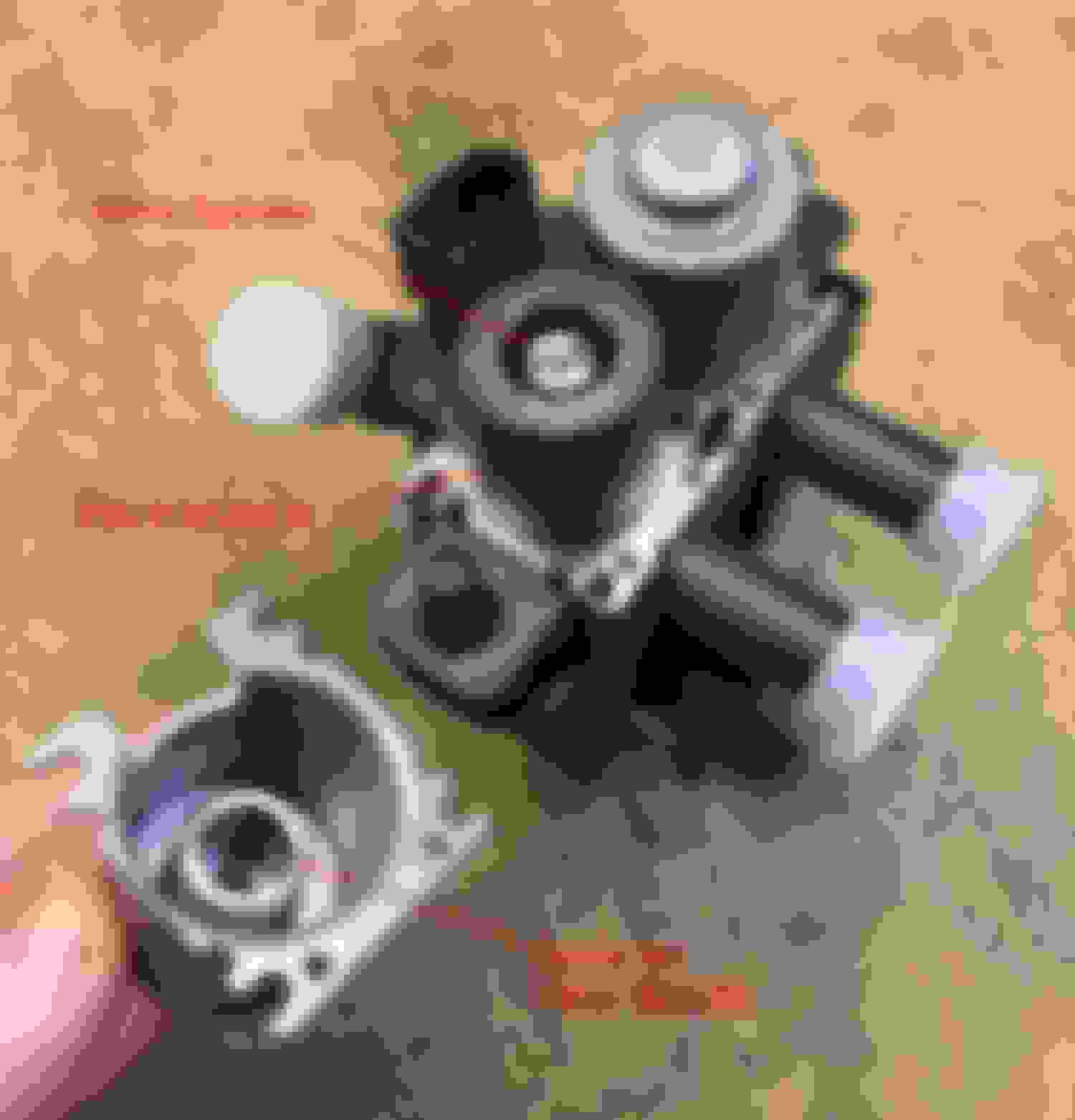
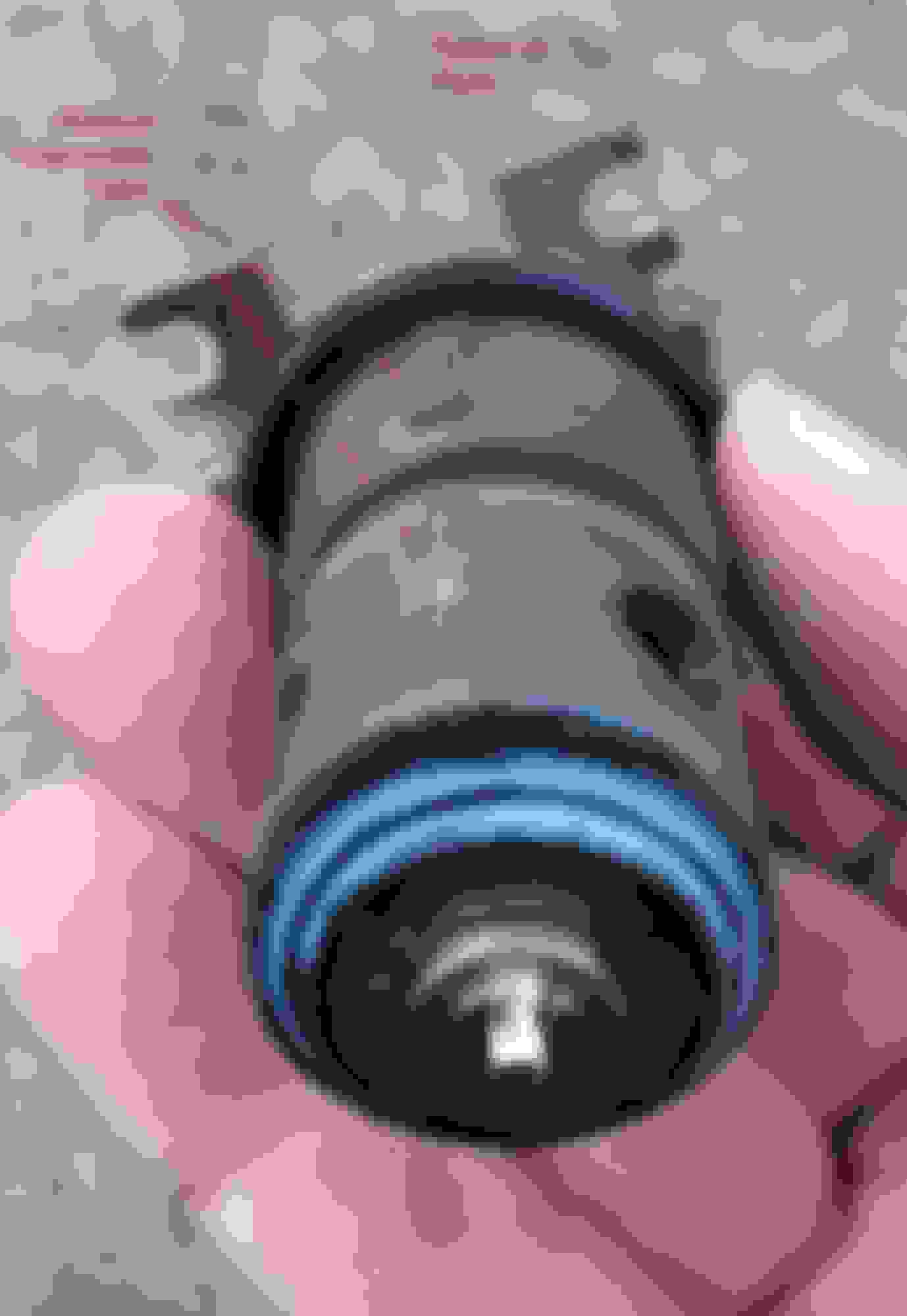
With both covers removed, the electromagnet assembly lifts straight off. Note the two O-rings, which fit under the electromagnet assembly:
With the electromagnet assembly removed, the individual valves simply lift straight out of the housing. All relative movement within each valve takes place inside the removeable portion. No wear takes place against the main housing, which in theory should last forever:
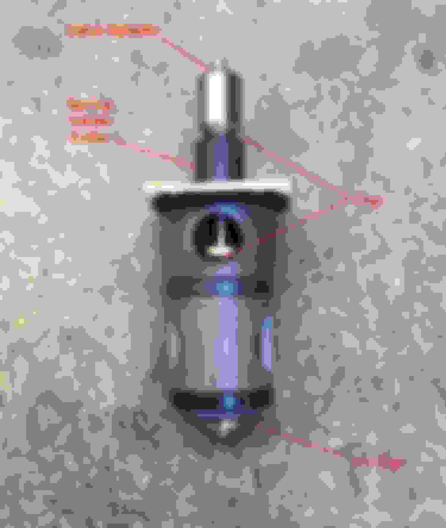
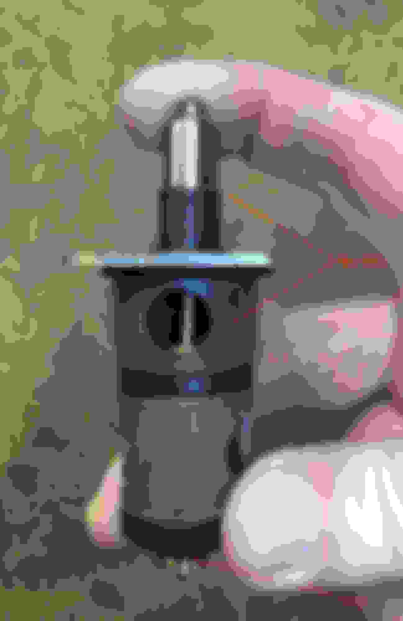
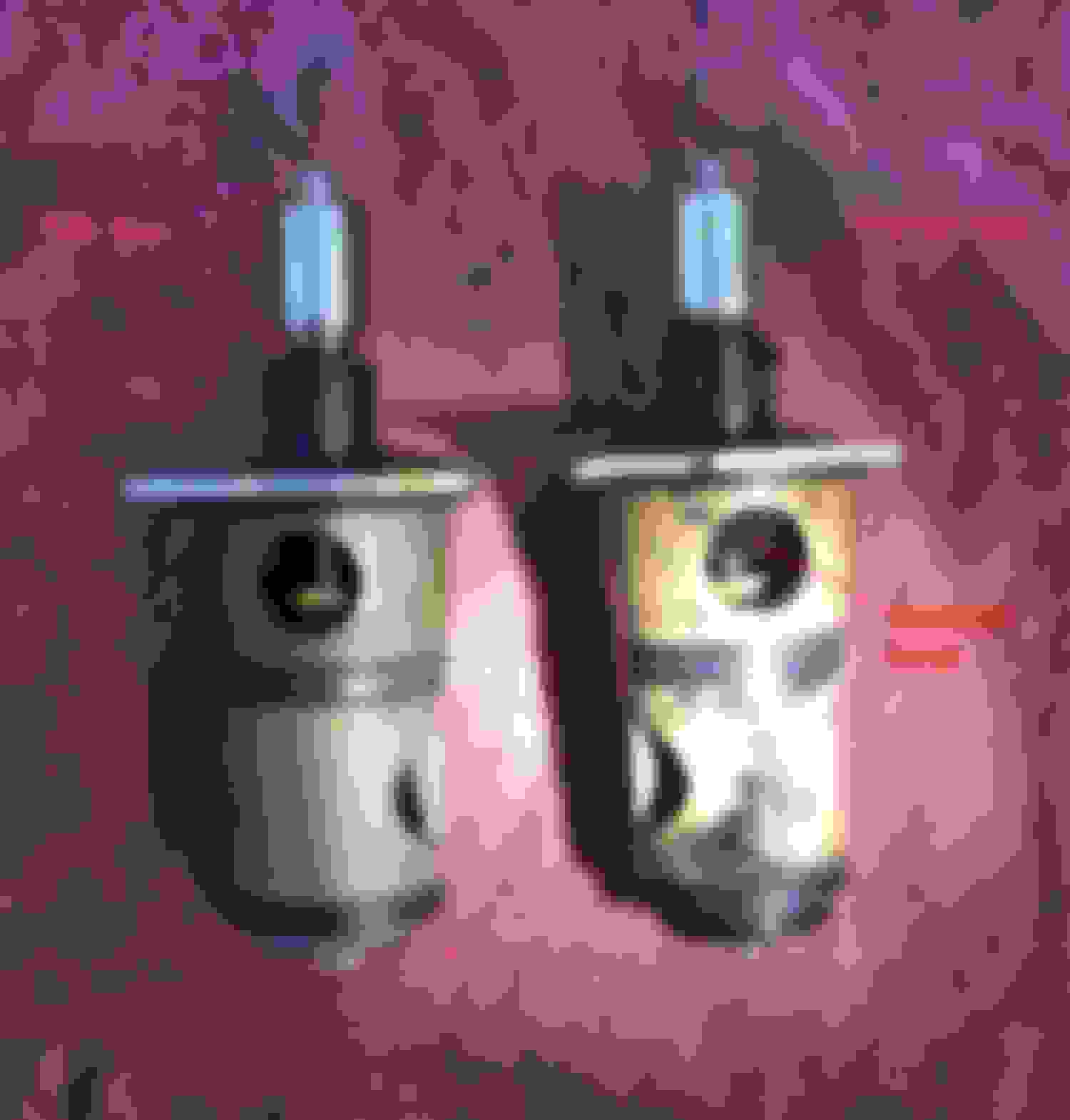
Here�s a close-up of one of the valves. There�s no need to disassemble the valve beyond this point. The spindle is spring-loaded to this open position. Hot coolant would flow to the respective side of the heater core. The spindle only moves about �� maximum. Note how the gap is closed at the very bottom, and open in the middle. There�s also a gap between the upper portion of the spindle and the collar around the spring. Although I�ve pointed out this upper gap, no coolant flows through this area. I�m only mentioning it so you can easily determine if the spindle is spring-loaded up (coolant flows = heat) or pushed down (no coolant flow = no heat).
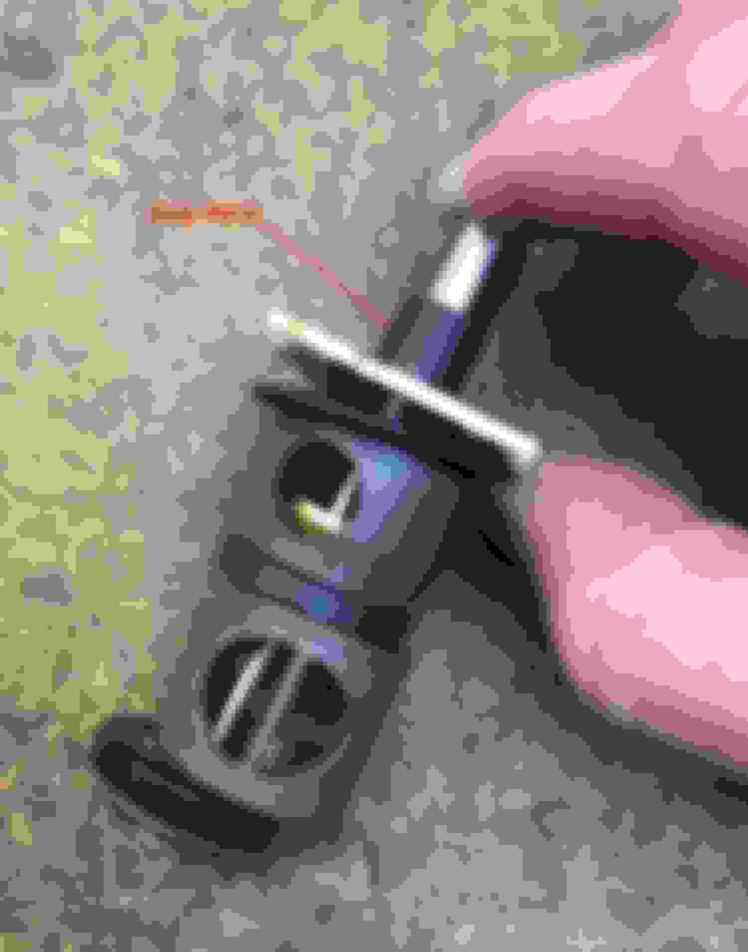
In this picture, I�m pushing down on the spindle, same as if installed and the electromagnet was energized to turn off the heat. Note how the gap is closed at the top, indicating the spindle is depressed. The gap in the middle is closed and the bottom is open. No coolant would flow to the heater core.
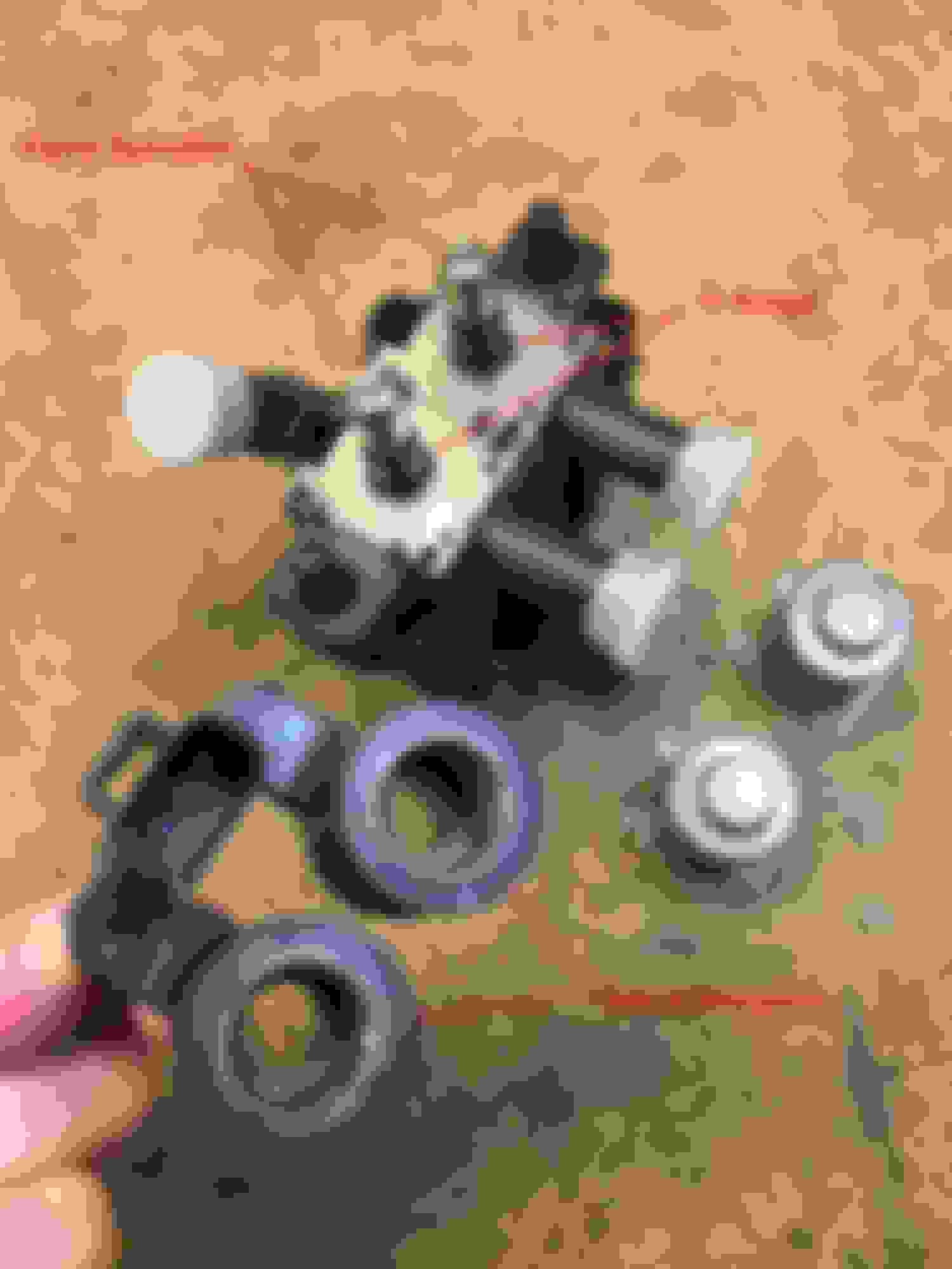
When it�s time to install each valve into the housing, the individual pieces must be properly aligned. The metal plate has a notch that must face towards the front of the vehicle (the side of the housing with the electrical connector). Each valve consists of an upper and lower half that must be orientated so the raised alignment tabs face forward, too:
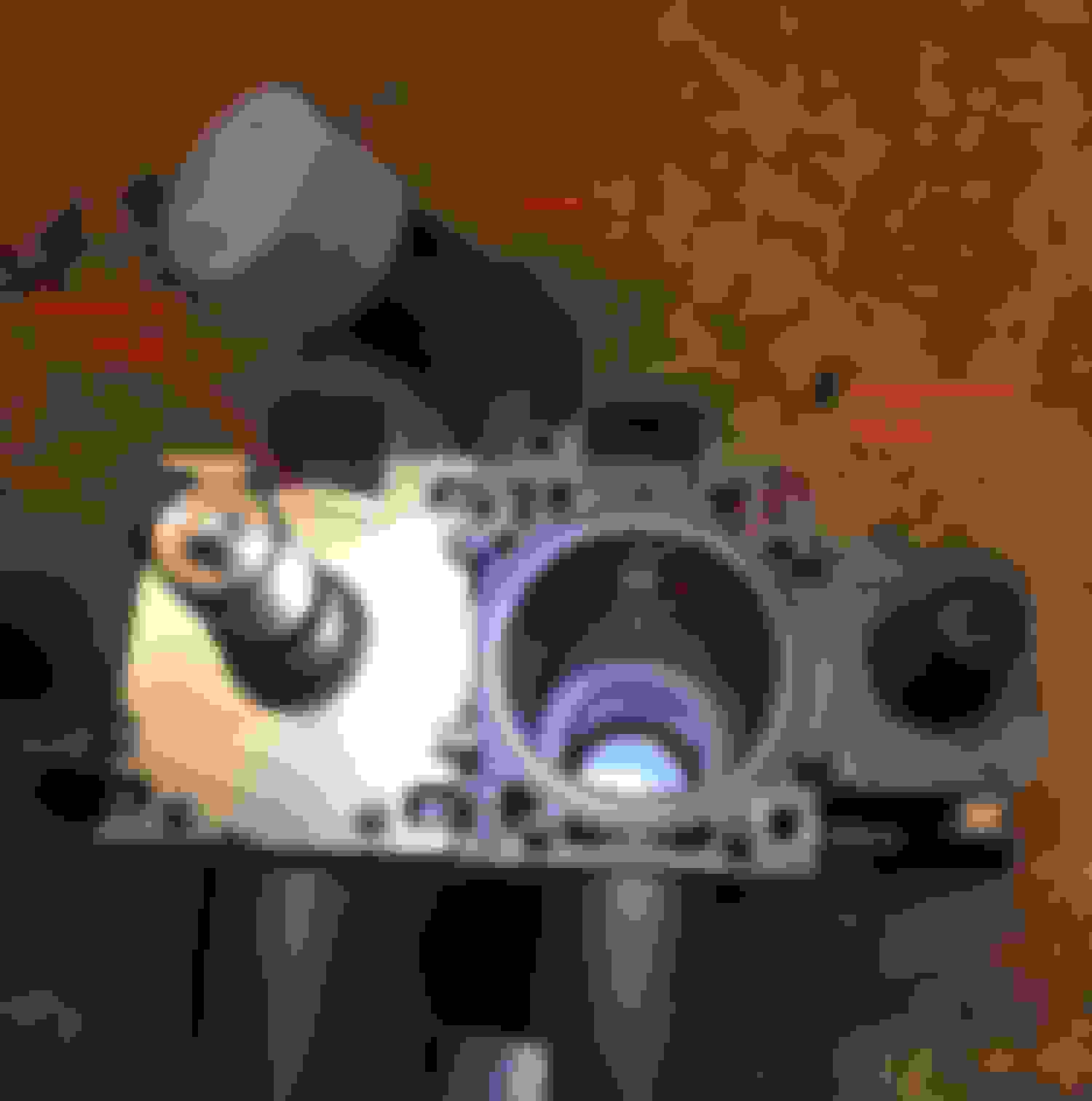
Here�s a view of the housing, showing where those two raised alignment tabs fit. Also note the large notch in the metal plate, which also must face forward:
When installing the individual valves, it�s important not to depress the spindle. As seen here, the individual pieces can shift when not held together by the spring-loaded action:
If I were to do this again, I�d slip a short piece of �� inside diameter hose over the top before installation. This would create a handy grip for working in a tight spot on the car, and keep from bumping the spindle and letting the pieces get out of alignment:
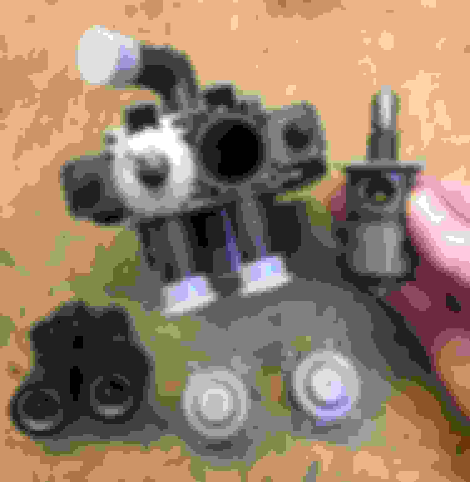
Let�s take a look at the electromagnet assembly. It�s simply two coils in a common housing, sharing one electrical connector. When each electromagnet is energized, the respective spindle is pulled down and coolant flow is stopped to that side of the heater core. When the electromagnet is de-energized, the spindle is spring-loaded open for coolant flow.
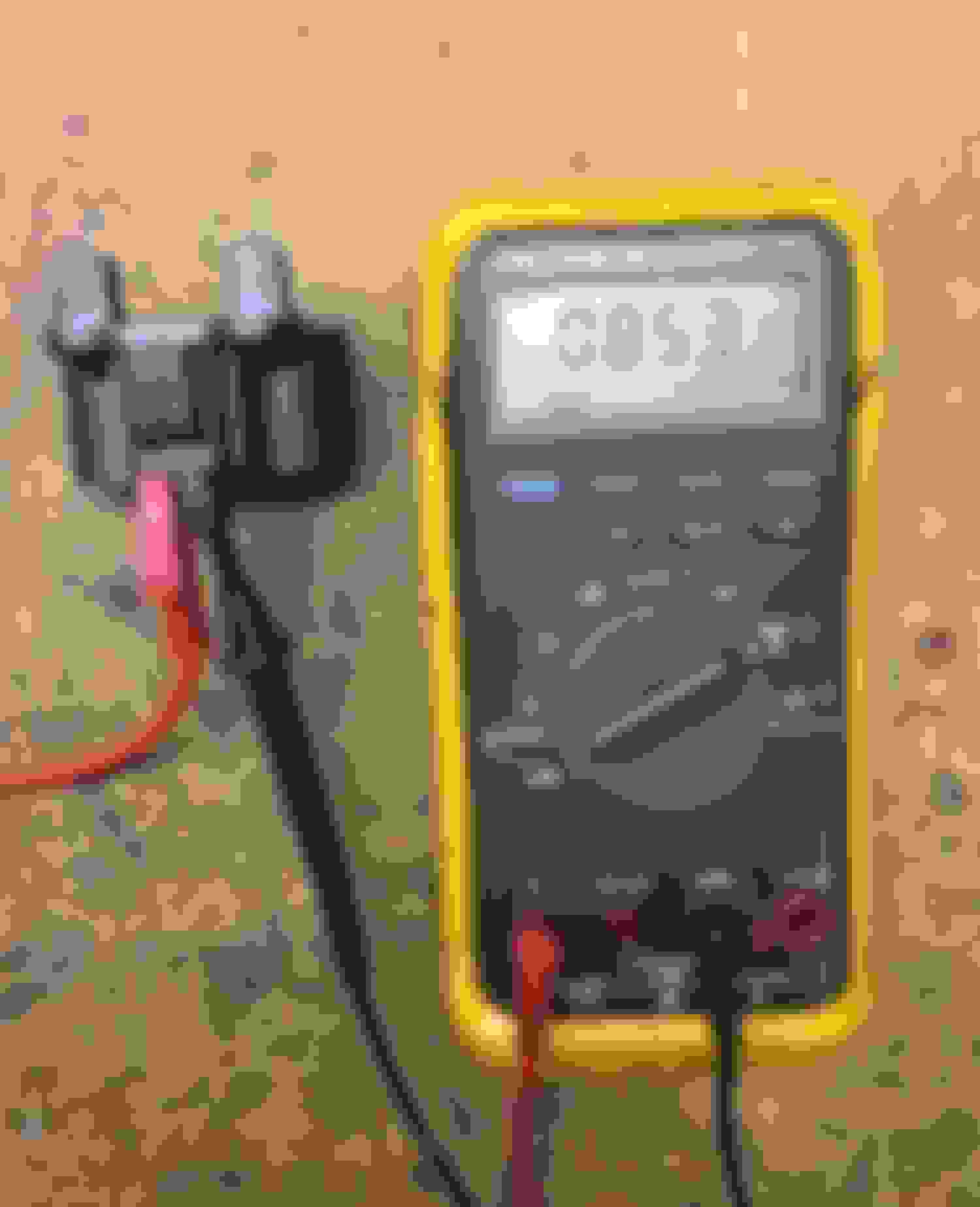
The electromagnet assembly is easy to test. Although I�m taking these readings on the bench, you can do these tests before removal, but access to the connector is tight on the vehicle. Here I�m testing resistance on one side, in this case between pins 1 and 2. I measured just under 15 ohms. Connect your meter between pins 2 and 3 for the other coil. If you measure between pins 1 and 3, that will test both coils in series, for approximately 30 ohms total:
Here�s I�m testing amp draw, which is a preferred method for testing. I�m using a variable power supply set at 13.5 VDC, which is comparable to system voltage with the engine running. For each coil, I measured about 0.85 amps:
Here�s a post-mortem of what I found with the old valves on my car. The passenger side was fine, but one of the seals had swollen on the driver�s side. I have absolutely no idea how this one particular seal failed, but the others were fine. All seals were original to the complete valve installed about 10 years ago. Note how the spindle could only spring-load partially open, which explains the reduced heater output:
So far we�ve mostly seen details of a shiny new assembly sitting on my workbench, with a comfy padded seat and plenty of fresh coffee. Now it�s time to shift gears and discuss how to work on the unit while still installed.
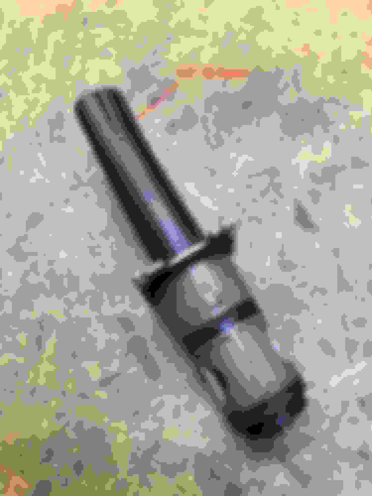
Perhaps I shouldn�t have to state the obvious, but open the hood for access. Make sure the engine has been off for at least several hours, as you don�t want to deal with hot coolant. Drain the cooling system. Remove the trim panel across the top of the radiator. On each side, remove the three bolts (circled in red) that secure the upper radiator mounts. This lets you tip the radiator forward a couple of inches, which improves access:
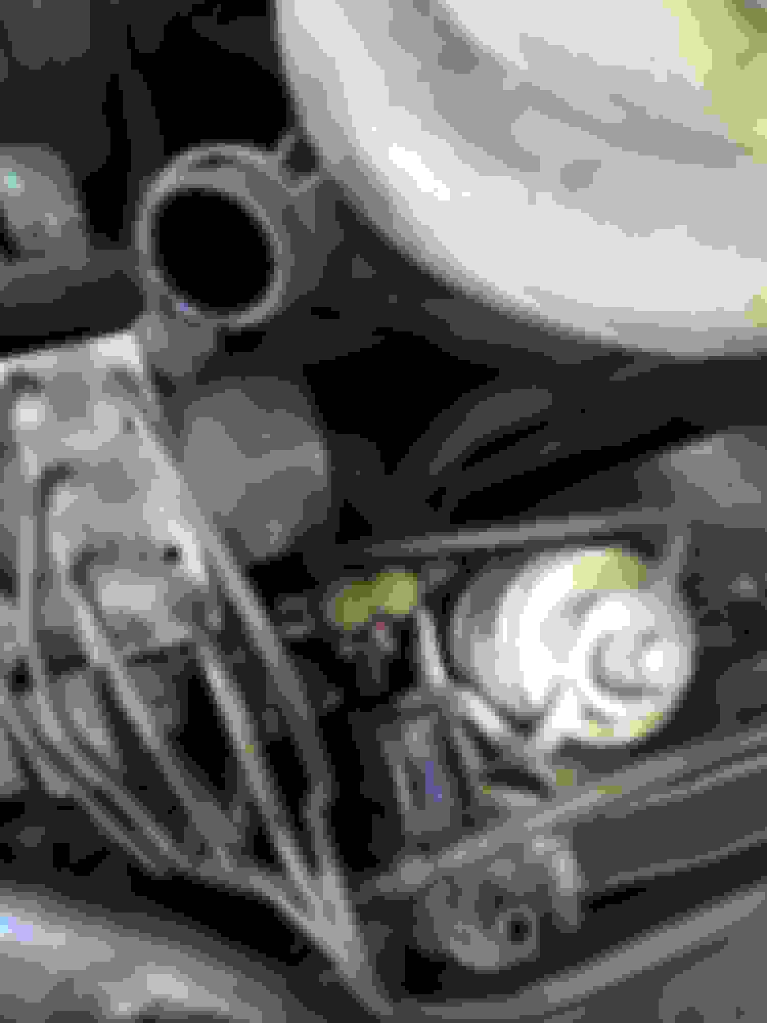
Next, disconnect the upper radiator hose from the radiator, and swing it aft out of the way. Remove the single bolt that secures the AC accumulator to the radiator shroud. You do NOT have to depressurize the AC system. The accumulator is connected via flex hoses, and can also be moved for better access to the DCCV below. If you look closely, you�ll note the trim panel above the radiator has not been removed yet:
Finally, here�s that pesky DCCV partially visible below the AC accumulator.
The single electrical connector uses Ford�s infamous sliding red lock, which has to be released first. Here�s a quick video explaining the process:
Access is pretty tight to remove the six Torx screws securing the two covers. I found the screw heads clogged with crusty debris. Take a moment with a small pick to break up the crud and then blow it out with compressed air.
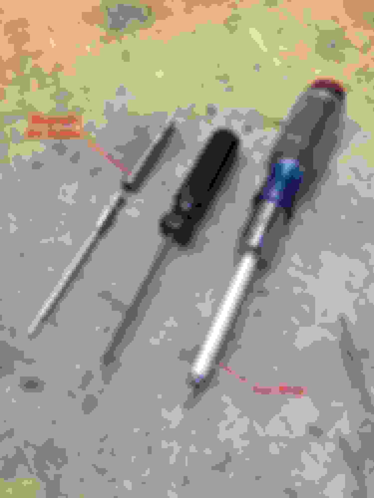
I do NOT recommend using a short Apex bit, as the body of the screwdriver will be too wide. You can reach the screw heads if you come straight in, but there�s no room to work from a slight angle. I recommend a long Torx bit with a magnetic bit holder, as seen to the left in this picture. In a pinch, you could make do with a Torx driver with a narrow shaft, but the magnetic action is very handy for working one-handed in a tight spot:
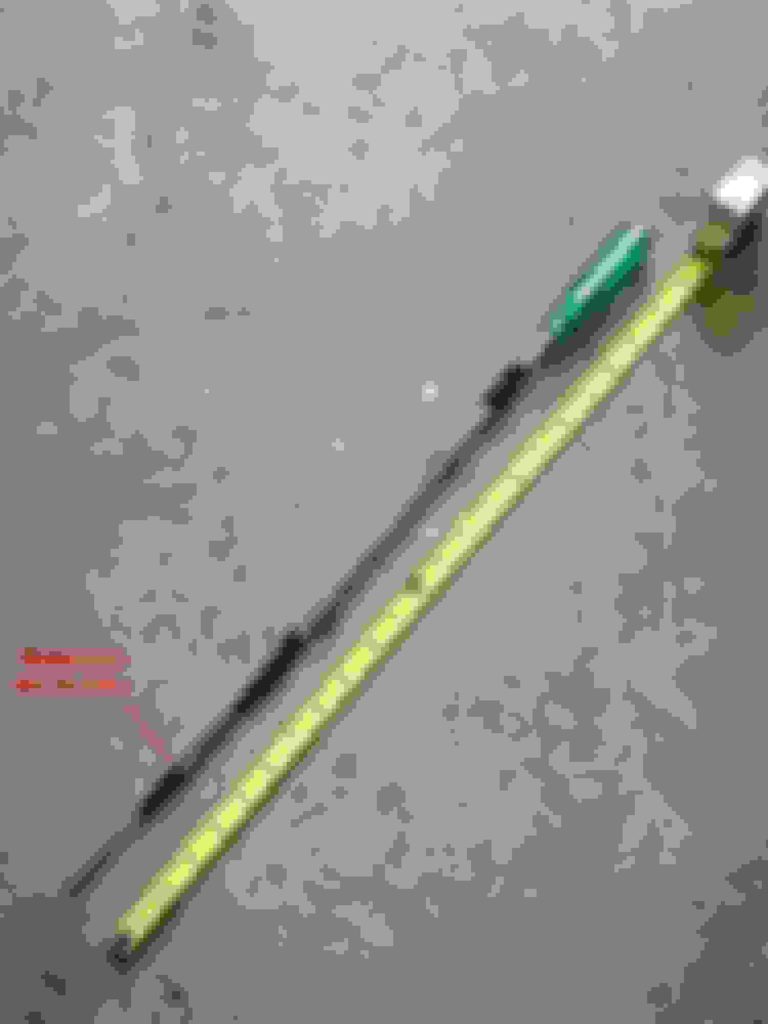
Here�s what I ended up using. It�s a long Torx bit with a magnetic bit holder and a long extension and drive handle. The overall length isn�t important. Note how I taped the connections together so nothing fell apart:
The actual repair is anti-climatic. Take your time and make sure the top of the housing is clean before installing the new valves. Hand tight only on the screws, as they go into a plastic housing. Do not overtorque them. I spent about two hours total swapping out the valves, and that included learning a few things the hard way. For example, make sure you clean out the screw heads before trying to loosen them. My first attempts were very frustrating, as I couldn�t get a decent grip to break them free. I also HIGHLY recommend using a long extension and magnetic bit holder, which allows you to work at a slight angle.


 10-01-2021, 09:48 AM