MAF Sensor wiring for an X350
#1
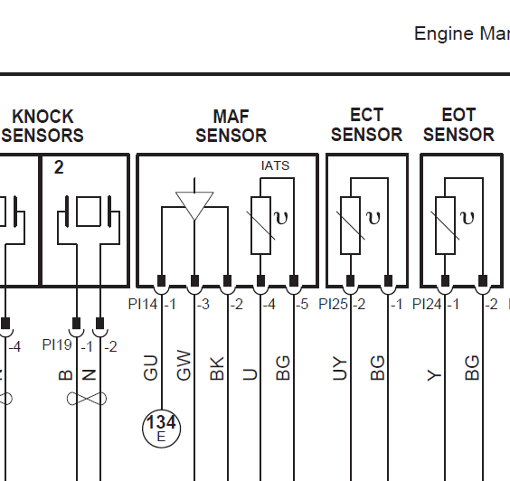
I have found several posts for MAF Sensors in the X300 forum etc, but none for my 2005 XJ8L in this forum. Please find attached photo of my MAF Sensor wiring. The colours are not particularly clear and are as follows (from left to right or more accurately from bottom to top):
Green/blue : Brown : Green/white : Blue ; Green/black
Which wire is the live feed, which the Earth and which the output to the ECU, please?
Green/blue : Brown : Green/white : Blue ; Green/black
Which wire is the live feed, which the Earth and which the output to the ECU, please?
Last edited by EsRay; 11-20-2017 at 05:36 AM.
#3
Thank you for this - Now I can test my MAF Sensor with a multi-meter and (hopefully) rule it out as a source of my ongoing problems!
Incidentally, I have downloaded the full electrical manual from the sticky post at the top of the x350 page. I even found the diagram you have kindly place before me, but I was totally unable to decipher what each of these wires do!
Incidentally, I have downloaded the full electrical manual from the sticky post at the top of the x350 page. I even found the diagram you have kindly place before me, but I was totally unable to decipher what each of these wires do!
Last edited by EsRay; 11-27-2017 at 11:34 AM.
#4
#5
#6
https://www.jaguarforums.com/forum/x...-p0405-192712/
I hope this link works?
The following users liked this post:
Don B (12-04-2017)
#7
Thank you for this - Now I can test my MAF Sensor with a multi-meter and (hopefully) rule it out as a source of my ongoing problems!
Incidentally, I have downloaded the full electrical manual from the sticky post at the top of the x350 page. I even found the diagram you have kindly place before me, but I was totally unable to decipher what each of these wires do!
Incidentally, I have downloaded the full electrical manual from the sticky post at the top of the x350 page. I even found the diagram you have kindly place before me, but I was totally unable to decipher what each of these wires do!
With a voltmeter, can really just check for 12v and ground. You will need a scope to see the output of the MAF sensor, and would need another working unit to compare the output.
I believe there are MAF reading ranges (g/sec) posted somewhere on this forum that you can check against. See if your unit is reading approx correctly at idle and at 2000 rpm via the scan data.
Trending Topics
#8
Hello (again) mhamilton,
You very obviously ARE an electrical engineer and for your sins I have designated you my very own electrical expert! There now, that'll teach you for being so knowledgeable!
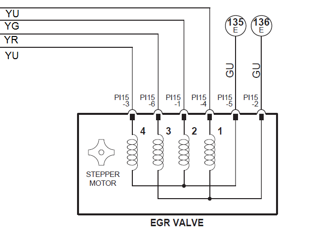
Please could you repeat the process above to show me which pin is the earth, which the 12-Volt supply and which is the 5 volt 'signal' on my EGR Valve connector. I have a Code P0405. I have inspected my EGR Valve and it is clean and unblocked, so either the solenoid has failed, or a supply, ground or signal voltage is failing. I think!
Last edited by EsRay; 12-04-2017 at 02:25 AM. Reason: Add photo
#10
#11
With the ignition on you should have 12v at the two Blue/Green wires at the harness plug.
To check the valve, I would unplug the EGR and put the ohmmeter from pins 2 to 4 and 2-6, and from pins 5-1 and 5-3 on the EGR itself. All should show the same resistance (coil check). Start there and see what you get. Any that are obviously open or way different resistance than the others will indicate it's time for a new valve.
To check the valve, I would unplug the EGR and put the ohmmeter from pins 2 to 4 and 2-6, and from pins 5-1 and 5-3 on the EGR itself. All should show the same resistance (coil check). Start there and see what you get. Any that are obviously open or way different resistance than the others will indicate it's time for a new valve.
#12
#13
Careful Higgins, Mr Hamilton (Sir) is my designated electronic expert!
Last edited by EsRay; 12-04-2017 at 12:14 PM.
#14
#15
Join Date: Feb 2014
Location: Crossroads of America
Posts: 19,574
Received 13,199 Likes
on
6,549 Posts
Yes, the values of the MAFS an intake air temperature sensor (IAT or IATS) are directly readable with an OBDII scan tool that can read live data and sensor outputs.
As a general rule of thumb, at idle a healthy MAFS will read about the same number in grams/second as the displacement of the engine in liters, so the MAFS on a 4.2L engine will usually read 4 to 5 g/s at idle. As rpm climb, the MAFS reading will also increase to 20 or 30 g/s or more.
The IATS will typically read a little higher than ambient air temperatures due to the air being heated as it is inhaled into the warm intake plumbing
Cheers,
Don
#16
Haha, not stepping on my toes, I'm far from an expert here! It's a full time job taking care of these cars.
Agree with Don 100%, the OBD scan tool is the way to go. I have an inexpensive (approx USD$100) tool that will give about 4-5 pages of OBD data points (PIDs). All the basics are there--MAF flow, air temp, coolant temp, MAP, TPS, fuel trims. However the full Jaguar SDD will let you see every data PID the car has to offer. I've never gotten SDD to work well enough to look through that myself.
You won't be able to read values directly from the MAF with a voltmeter.
The following users liked this post:
Don B (12-04-2017)
#17
#18
Join Date: Feb 2014
Location: Crossroads of America
Posts: 19,574
Received 13,199 Likes
on
6,549 Posts
Any good OBDII/CAN scanner that can read live data can give you a lot of information. Many of us have the Torque Pro app (about USD $5) on our smart phones used in conjunction with a ELM327 bluetooth OBDII adapter (available from many sellers on eBay form $10 or less). This setup offers pretty good live data, thorough reporting of P (Powertrain) DTCs, as well as some Mode $06 data which can help understand pending DTCs or why P1000 will not resolve to P1111.
For an affordable hand-held, I'm currently enjoying a Launch Creader X431 VIII, which has very impressive abilities for its size and cost and can read more than just the basics on a wide variety of auto makes, including Jaguar.
My old hand-held was an Innova 3130b, which has decent live data but not current state-of-the-art.
In order to read the proprietary Jaguar DTCs that begin with the letters C (Chassis), B (Body), and U (Undefined, mostly Network), you need a high-end system. I have the dealer-level Jaguar Symptom Driven Diagnostics (SDD) set up on a laptop and used with a Drew Technologies Mongoose cable. I also have Autoenginuity, a high-end PC-based third-party system, but I have not purchased the Jaguar enhancement module that would give it capabilities similar to SDD.
Cheers,
Don
#19
Hi Don,
thanks for all the info, fantastic. To go with an smartphone app seems the most tasteful solution to me since I already have the Bluetooth adapter. I use it on my german car with great benefits. Will the Bluetooth adapter and smartphone app work on my 2000 Xkr also?
Regards,
Higgins
thanks for all the info, fantastic. To go with an smartphone app seems the most tasteful solution to me since I already have the Bluetooth adapter. I use it on my german car with great benefits. Will the Bluetooth adapter and smartphone app work on my 2000 Xkr also?
Regards,
Higgins
#20
Join Date: Feb 2014
Location: Crossroads of America
Posts: 19,574
Received 13,199 Likes
on
6,549 Posts
Hi Don,
thanks for all the info, fantastic. To go with an smartphone app seems the most tasteful solution to me since I already have the Bluetooth adapter. I use it on my german car with great benefits. Will the Bluetooth adapter and smartphone app work on my 2000 Xkr also?
thanks for all the info, fantastic. To go with an smartphone app seems the most tasteful solution to me since I already have the Bluetooth adapter. I use it on my german car with great benefits. Will the Bluetooth adapter and smartphone app work on my 2000 Xkr also?
Many of us use the Torque Pro/ELM327 bluetooth adapter on X100 and X308 Jags, so yes, it should work on your 2000 XKR, although some members have reported occasional glitches on their particular vehicle. You'll just have to try it.
I should have mentioned that some members are using other smart phone apps such as Dash Command, so you might search the forum to see if any pros and cons of the different apps have been reported. I've been overall very happy with Torque Pro for the minimal cost. I purchased ELM327 adapters to keep in all our cars, so anywhere we go I can do basic diagnostics even when I don't have my more sophisticated tools.
Cheers,
Don
Last edited by Don B; 12-05-2017 at 07:28 PM.


