When you click on links to various merchants on this site and make a purchase, this can result in this site earning a commission. Affiliate programs and affiliations include, but are not limited to, the eBay Partner Network.
The 2001 XJR transplant into the Mark 2 has been running fine until this morning - no power to the fuel pumps. Relays and fuses all fine. I have battery power to both pump relays (circuit 33), and I have switched power to both pump relays (circuit 1). There is no power making it to pump 1 (R4) but the relay closes and holds until switched off. There is power to pump 2 (R1) for approx 1 second, after which the relay opens. No trouble codes. Any thoughts appreciated.
Just finishing up the interior wood - some of this should look familiar to you folks.
Last edited by Doug Dooren; 03-17-2018 at 12:49 PM.
I followed your build and have been looking forward to the final completion. I know you swapped the entire harness to the XJR into the Mark. Most likely your problem is the inertia switch has tripped and it will disable the fuel system until reset. Locate and reset the switch and see if that resolves the issue.
- no power to the fuel pumps. Relays and fuses all fine. I have battery power to both pump relays (circuit 33), and I have switched power to both pump relays (circuit 1). There is no power making it to pump 1 (R4) but the relay closes and holds until switched off. There is power to pump 2 (R1) for approx 1 second, after which the relay opens.
It's the other way around, battery power is Circuit 1, ignition switched power is Circuit 33. The fact that both relays operate, suggests that it is not the inertia switch. The brief engagement of the relay for Pump 2 is probably normal as Pump 2 will only come on at higher rpm.
If Pump 1 does not get power when its relay is on, I would first check the sockets of the relay (at pins 3 & 5 or 30 & 87 depending on the markings on the relay) and the fuse for any corrosion or signs of burning. It is not uncommon that, due to fairly high current, the female connectors at the pump relay and the fuse sockets get overheated when somewhat corroded causing them to distort/weaken and lose contact.
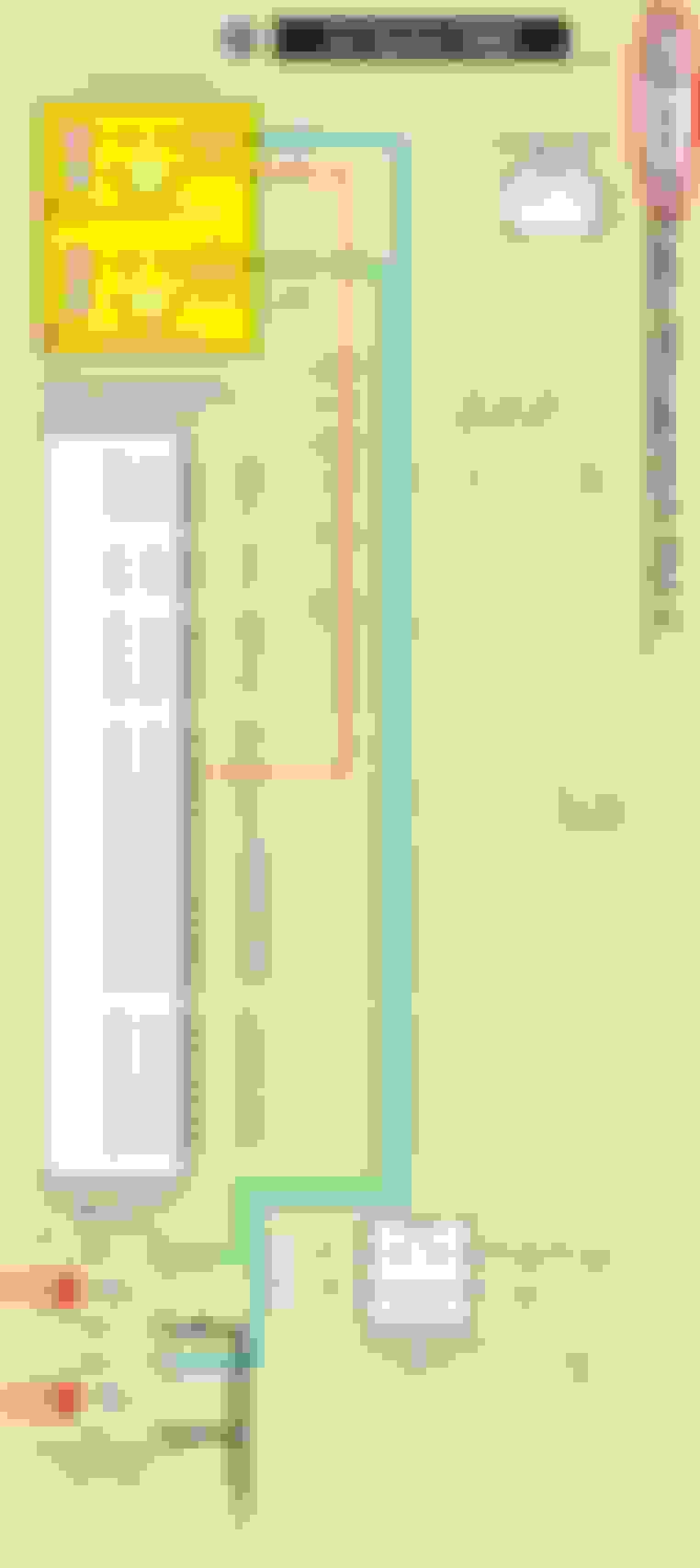
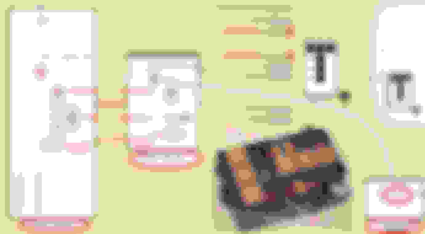
These pics I made are for the X308 with the 2 pump configuration . Editing If the relay closes for a moment then opens there may be a compromised wire from the source of control power at point 29 as the ECU provides a ground to pull the relay control coil . Loose ground on the other side of the pumps ? The point 33 you are referring to may be that on the Mk 2 which in that configuration that power leg may be relay controlled . I would need to see the Mk 2 wiring guide that I don't have . You can jumper the power contacts in the relay with a blade type connector and a short heavy wire with the battery disconnected because of the high current arcing damage potential . Or you can bring power in at the relay socket at point 5 that goes to the pump . Notice on the X308 configuration the fuses are after the relay .
Last edited by Lady Penelope; 03-18-2018 at 01:44 AM.
Something I forgot to mention in the X308 ECU is the # 1 pump will run for 3 - 5 seconds and then turn off . Safety / crash design feature . It will turn back on for the duration of the drive by seeing engine rotation through the crankshaft position sensor . If there is a unsuccessful start the ECU will provide the ground to start the # 2 pump . This can mess you up in troubleshooting . Do you see the tach respond to the engine rotation during starting attempts ?
The control aspect of the pump relays can take some effort to resolve and may want to just jumper the relay power sockets to see some positive progress if you haven't been able to start it after conversion . You can get back to the designed control later .
There is the inertia / crash switch that you my not have addressed in your wiring adaption for the conversion .
Thanks for the great feedback. MS, I don't see any evidence of corrosion, but my eyes aren't what they used to be and this box does not live in the best environment next to the battery. I've also relocated fuses and relays in an effort to resolve any issues with the contacts, but no change.
LP, everything was carried over from the XJR to the Mark 2, so the only thing left of the latter is the body and front suspension. A compromised ground from the ecu might be it- I'll start by checking the wire on the 10A circuit from the heel board to boot boxes. I've had these harnesses in and out numerous times during the build and that's never a good thing with 17 year old wiring.
Re "loose ground on the other side of the pumps?" - meaning inside the tank?
Jumpering the power contacts is a good suggestion - will probably go there to get the beast running again to finish the build and come back to this. Any thoughts as to why I'm not getting any DTCs?
Although the wiring guide page 59 and 61 does not show a case ground vs. the many wire grounds in the lower left side on page 41 it wouldn't hurt it if you gave it one through the mounting hardware depending on how you have it mounted . The 96 X300 requires one and from experience on other ECU's they will not function unless they have one .
The pump motor ground are the 2 black wires coming out of the 4 wire pump connector and are grounded to the frame on the side of the battery . Yours may be different on the Mk 2 so you would have to follow the wires with you eyes . Since you had a pump action for a little bit the grounds may be in place , just loose .
The CEL code for the crankshaft position does not always show and they can partially fail and give you one aspect of it's usage but not all .
You can source the control power from and source including the positive battery terminal as the pulling coil winding have a resistance and will not short the wire and overheat .
Without looking the LH fuse box power source probably has to have that fuse box king relay closed to enable power though that 10 amp fuse . Yes in looking at the wring guide . The ECU provides a ground to pull the control coil closed as it is ground seeking . You can put your finger an the ignition positive relay and feel for the click as you turn the key ( how the king relays are controlled ) and if no click you can swap the ignition positive relay .
Since you said you had the pump action for a while it points to the crankshaft sensor ( or it's wiring to the ECU ) as you require 3 clicks of the fuel pump relay ( on - off - on ) during the engine starting sequence and sees engine rotation for the commanded 3rd click .
Last edited by Lady Penelope; 03-18-2018 at 09:46 AM.
Sometimes it's the simplest things. I had my wife crank the engine while I manipulated wiring in the boot and the beast fired right up. It appears to be the wire to female plug connection at the fuel tank - power in the wire but dead on the terminal side where I was taking readings. Thanks again for the help everyone.

 03-17-2018, 12:42 PM