When you click on links to various merchants on this site and make a purchase, this can result in this site earning a commission. Affiliate programs and affiliations include, but are not limited to, the eBay Partner Network.
1. My daughter and I extend congratulations to Bobcat and her family!! She a cat lady, I not so much. Although I have "guest" cats in my garden.
2. Could it be that one of the "ballasts" is actually a capacitor. Merely there to suppress ignition noise in the radio ?
3. I could not see the rim flanges well enough so I guessed. Wrong, If from a 31, they are 19's not 21's.
4. Weld !!! Not as far fetched as you might think. My first car, a 23 T suffered from poor tires. Somewhat a WWII casualty. I came up with the "brilliant" idea of discarding the wood spokes and the 30" clinchers for "modern: 16"'s.
Yup, I scrounged up some left over tires and odd wheels here and there. I found a former US navy Sea bee now in the weld business.
Yup welded the 16's to the hubs from which I removed the wood.
Grant......No worries mate....I hate the Parts Book and manuals that are so confusing when they list cars going to different countries with slightly different parts/wiring.
I also have the large fold-out wiring diagram that was in the 77 XJ6 Owners Manual, and that is damn confusing as well.
I agree with you.....I believe the White Ballast is the running one (reduces voltage from 12 to around 7 volts with engine running), and I was guessing that the shiny one was for the starter-cranking mode, and maybe reduced voltage to 9 or 10 volts. I pulled that white sucker off today and did some testing, along with the shiny one.
I tested the Ohms on the white one, and then tested to see if it would reduce the volts when a battery charge is applied to it:
Ohms - 5.0 M ~
Volts - 12.45 Volts ran thru, with No Resistance (Battery was at 12.45). Same results when changing the meter + and - leads. So, looks like the White Resistor has no resistance. So, I peeled the mounting piece off to open her up to clean, and managed to scrape some dirty crapola from around the wound wire, but then it appeared that the wire was supposed to be sealed in this material. Not sure. After cleaning well, I got the same readings.
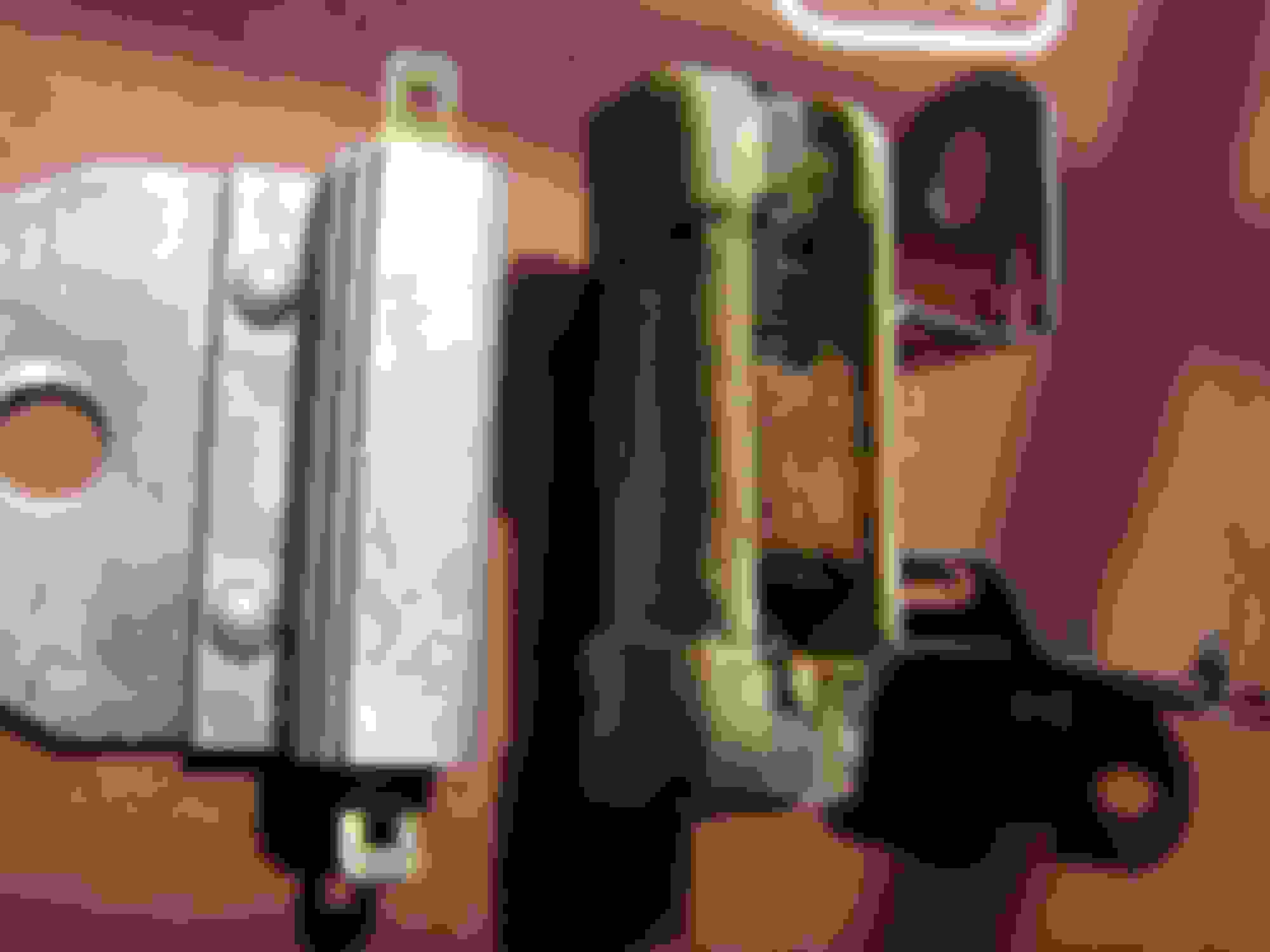
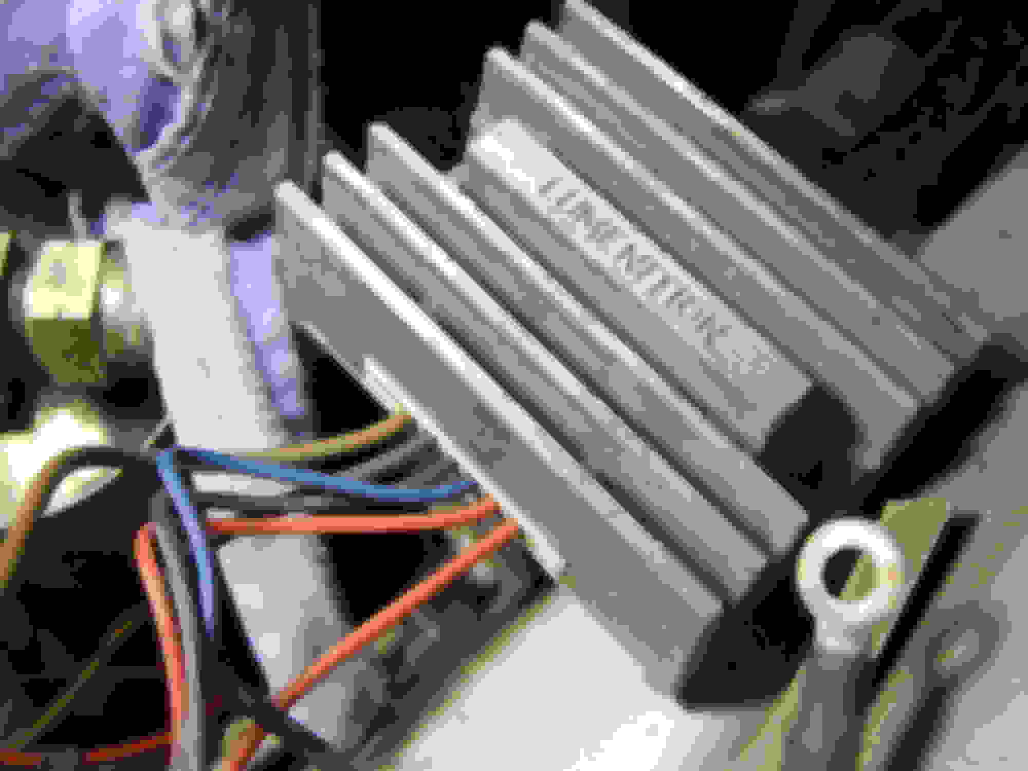
Shiny Resistor on left and White Resistor on right.The Shiny Resistor gave readings of:
Ohms - 36.0 M ~ (~ is my symbol for "Ohms")
Volts - Full 12.45 volts running through, with no resistance. Same as the white one. I suppose both of the resistors are "shot"? The Shiny one says "9.5 Ohms"/ 13 BR" on it.....stamped on the side of it.
Ballast resistor with no resistance, dunno.
Test teh +ve of the coil with the engine running, it is likely to be 12v ish.
With no resistance, there will be 12v at the coil, and IF that was a resistor spec coil it would last about 30 minutes with 12v slamming through it.
You appear to have a rats nest of left overs.
Back to basics, AFTER confirming the volts at the coil with the engine at idle.
12v at the coil, good. Locate the 12v supply wire attached to the White ballast, attach it to the +ve of the coil. Check the other wires on the same ballast terminal as that supply wire, and MAYBE that is where the feed for the Luminition is coming from, dunno again.
That then reverts the car to standard 12v ignition as Carl mentioned earlier, SIMPLE.
If you find 8v or so at the coil with the engine at idle, the ballast is working, leave it alone, tidy up the wiring, remove the Shiny thing, and move on.
I have no idea of the wiring schematics for the Luminition, but 12v Ign feed will be one of them, and that could easily be one of the wires attached to the Ign supply side of the ballast.
Thanks for the feedback above. Allow me to throw in another curve ball to throw us off even more:
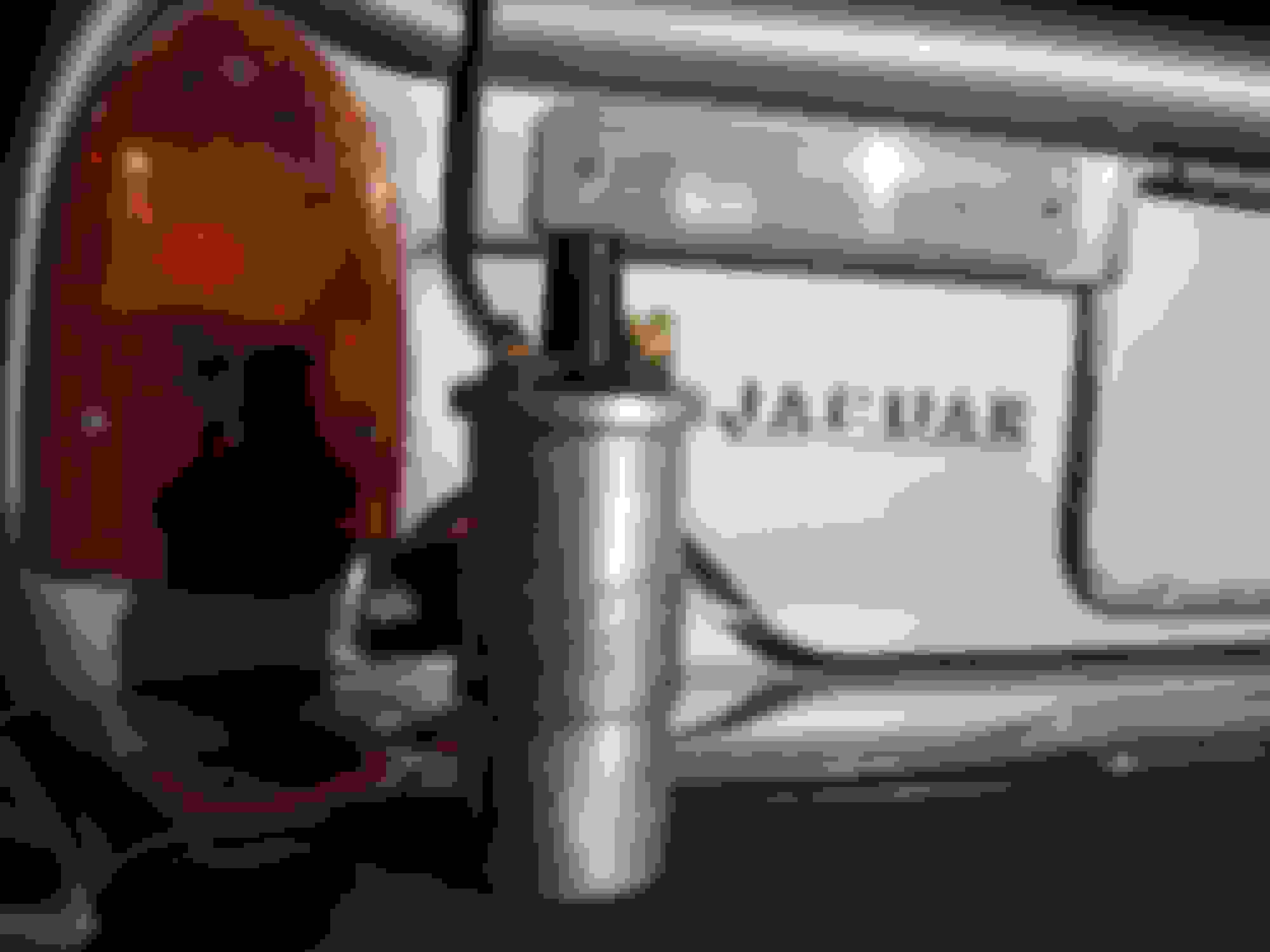
Here is the wascully coil:
Here is the coil with a date stamp of 1977.
The part number is I6C6 / 45232E. When I researched it, I found that it was a "6 volt" coil. I did a test to see if it was good, and the readings were consistent with a 6 volt coil:
Primary winding test (Test leads on + and -)........1.6 ohms.
Secondary winding (Leads to the "fire hole/ hell pit" and either the + or -)....6,750 ohms
Coil tested good.
So, if both of those Ballast Resistors are "no good" based on my first test, then the coil would be getting a full punch of 12-14 volts, and as you said, those electrons slamming thru it would make it blow its top. Did I test the Ballast Resistors properly, or does there need to be a load from the coil to test properly? It just does not make sense that voltage running thru that spring inside the white ballast does not burn up juice and reduce the output voltage.
How can this wire winding not create resistance? As you suggested, I wish I could just crank up the engine and test the coil. However, this engine has not run in 20 years, and I just rebuilt the carbs and have fogging oil soaking in the cylinders. I wanted to resolve the electrical issues before putting the carbs back on since I have so much more space to work now.
You are right.....the Luminitron gets its power from the same plug-in wire that goes into the white ballast (the hot 12 volt side). (The Lumintron is good for either 6 volt or 12 volt coils (but you need a working white ballast resistor to use the 6 volt coil). I downloaded the wiring diagram for the Lumitron already. So, if I want to keep it original and use the 6 volt coil, looks like I need to snag at least a new white ballast.......but if I knew what the shiney one was for, I might need to snag a new one of those too.
The shiny thing is a left over from the Opus Original system, and is redundant, and on top of that doing nothing unless the Opus is still lurking around, so remove it and move on with the Luminition replacement.
Again, I am "assuming" this engine is running???? and you are chasing a tidy up????
If so, worry not about too much, test the voltage at the coil +ve with the engine running, and if its around that 7 or 8, drink some more, the Jag is happy, and The Prince of Darkness had not taken up residence.
My test, after much inner lubrication, is apply battery +ve to one side of the ballast, then attach the Red lead of the meter to the other end, and the Black lead of the meter to the -ve of said battery, read the numbers.
Grant.......Guzzzzzle, guzzzzzzle, guzzzzzzzle........youre driving me to drink, mate. As Commander Cody sang, "Youre gonna drive me to drinkin,
If you dont stop driving that Hot.....Ride........Lincoln."
The problem with removing the Shiny Ballast is that there is a green wire also connected from it, and I still have not tracked down where that Green Combat Wombat goes to. Dern Jag wiring diagram is also confusing.
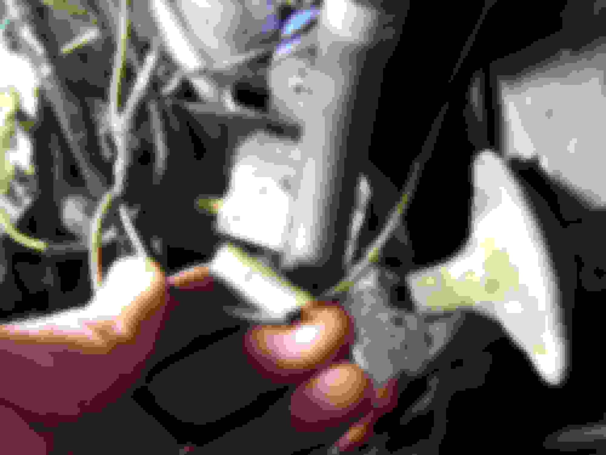
In this pic, you see me holding the white wire with a blue spiral stripe. It goes into a connector with a green coming out, and this connector plugs into the right side of that shiny Ballast resistor behind it. The green wire was then cut to expose the copper and twisted into the brown wire. This brown wire goes to "-" negative side of the coil (in the pic this is the upper right side, and the brown wire is unplugged and laying near the + side). Blue stripe and green wire plug into right side of shiny Ballast.
The other end of this brown wire goes into the Lumitron: Based on the Lumitron wiring directions, this is correctly routed to the "-" side of the Coil.
So, is that "-" negative side of the Coil just a ground? If so, why is that white/blue spiral stripe wire spliced into it? And what was the green originally for?
My testing of the Ballasts was exactly as you said, but I got "0" resistance. Still dont know how that coiled resistance wire in prior pic does not act like a mini-heater and create resistance.
Still dazed and in the corner, held up by the ropes..............and what do I hear:
"Float like a butteryfly,
Sting like a Bee.
Here comes the punch of Ali"
BOOOOM........BANGGGGGG.......Out goes tha lights.
That White wire with the Blue spiral is the feed for the tacho, and is generally attached to the -ve side of the coil.
The pictures of that shiny ballast show a terminal with nothing connected, so unless it is connected at both ends, the thing is basically being used as a connector only. So, unless there are wires at both ends, that Shiny ballast is NOT being used for any running item. Silly really, and splicing as you describe is flaky at best.
Solid Brown on Jags is 12v LIVE. Solid Brown with a Black trace is switched live, and usually unfused.
Carl......Good input. So I know the white Ballast Resistor is supposed to reduce voltage going to the 6Volt coil.......so, the shiny one could be the capacitor as you suggested. And I dont give a hoot about using the radio in this car, so that shiny one is probably not needed. Grant would be happy to see me toss it over my shoulder and get moving with the project. GettyUp!
Grant....OK, so we know the white/spiral blue wire should go to the "-"negative of the Coil, which it was.....so that wire is good. Im guessing that whoever installed the Lumitron did the splice of the tacho wire after-the-fact. He found that the tacho was not working, and made a quick cut of the Lumitron brown wire and did the splice to make the customer happy. The blue spiral wire was plugged into the right side of the shiny resistor/capacitor when I started working on the car, but dont recall any wires plugged into the left side of the shiny resistor......so, as you said, it would be just acting as a "fancy" connector.
I bet the green wire he used for this splice should have been plugged into that green female wire in the left of the picture. I still have not discovered where that green wire goes.
With all this input from everyone, now I am thinking that a wire was supposed to go from the Coil "-" negative terminal down to the left side of the Shiny Resistor (Capacitor?). Then the tacho picked up the electrical signal on the right side of the S.R. (Capacitor), and onward to the tacho. This would reduce ignition noise to the tacho and perhaps the radio..........and that makes me wonder if that green wire which is connected into the blue spiral wire is perhaps the feed to the radio?
1. My daughter and I extend congratulations to Bobcat and her family!! She a cat lady, I not so much. Although I have "guest" cats in my garden.
2. Could it be that one of the "ballasts" is actually a capacitor. Merely there to suppress ignition noise in the radio ?
3. I could not see the rim flanges well enough so I guessed. Wrong, If from a 31, they are 19's not 21's.
4. Weld !!! Not as far fetched as you might think. My first car, a 23 T suffered from poor tires. Somewhat a WWII casualty. I came up with the "brilliant" idea of discarding the wood spokes and the 30" clinchers for "modern: 16"'s.
Yup, I scrounged up some left over tires and odd wheels here and there. I found a former US navy Sea bee now in the weld business.
Yup welded the 16's to the hubs from which I removed the wood.
With a stumble or two, it worked!!!!
Carl
JagCad/Carl.......I was just checking prior posts and I see you posted comments a few days ago which I never saw......sorry about that. Late reply:
1. Thanks to you and your daughter for the thumbs up on poor ole Bobcat and her liter of kittens in the Jag's front seat. They are still there, too young to move them yet.
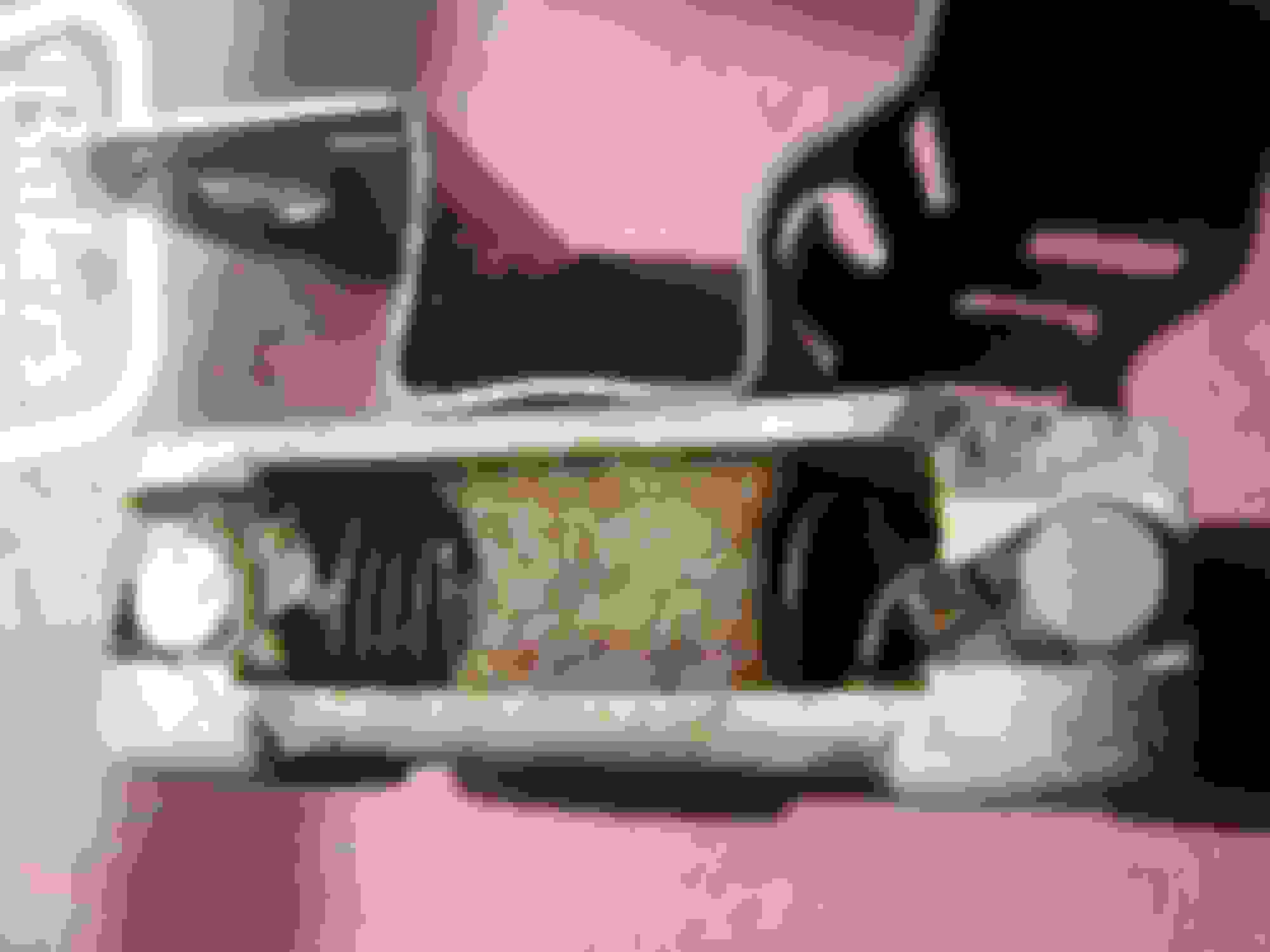
2. One of the ballasts could be a capacitor......Wish I had seen this comment earlier. Thats a great suggestion. I do not understand the Jaguar Parts Book, which I attached a picture in a prior post.....It shows both of these Resistors/capacitor in the book, but the book does not give names to any of the parts. When I do an internet search for that part number C.44458, I get nothing.
3. Yep, the wheels are from a 1931.......a bit large for those Jag fenders.
4. Great way to modify/weld those wheels from 30" to 16"......and of course, it would be a Seabee doing the welding. My dad was also a WWII SeaBee (was on Okinawa when the atomic bomb was dropped on Herishima), and he also became a welder after WWII. He is now living with me, and turns 97 tomorrow.......like the Timex watch, "He takes a lickin, and keeps on tickin".
I found the Lucas "shiny resistor" on Ebay. It is called a "Drive Resistor". Does anyone know what a "drive resistor" is for? Is it for noise suppression for the radio?
How do you properly test one to see if it is good?
I just deleted the Ebay pic.....but it showed the exact resister in the Lucas box, and it was called a "Drive Resistor".
Last edited by 1977JagwireXJ6; 04-26-2018 at 05:56 AM.
On my S2 6cyl cars, the Green wires, and I do forget any trace colours now, were for the temp sender, under the manifold near the front carby, and the feed TO the a/c compressor on the LH side of the engine. That A/C wire traveled across the top edge of the timing cover, where the head meets the timing cover.
Drive resistor is a phrase I do remember from the Opus days, they really did have odd words etc for simple items they usedin a very complicated system.
Looking at those snaps, I would be doing a serious rewire, ONE wire at a time and a rethink of what is doing what. That rats nest is going to reek havoc with any reliablity you are seeking.
Grant......Yep, you are right. My temp sender is way up front (toward radiator) under the manifold and has a green wire coming off it. The previous owner did tell me that the temp gauge was not working 20 years ago, and since it is unplugged and used as the sacrificial splice wire by Mr. Jerry Rigger, then maybe I can do a continuity check and see if that is the case.
Yep, a real ratzzz nest of a mess.....bigger than a rat, maybe a Wombat-mess.
But, what the heck is a "Drive Resistor" supposed to be for?
Another oddity for me was JagWire's phrase "Rev Counter" instead of just saying "Tachometer". At first I thought there was some kind of electronic counter that sent a signal to the Tacho.
Update: I tried testing both ballasts when they were off the car and after a thorough cleaning. They both read that a full 12.5 volts was going in one side and coming out the other side. I then did some research, and learned that you test them only "under a load". So, I hooked them back up into the car with the coil, turned the key on to get power to them, and then did the test. Got 12.5 volts going in on one side, and the same 12.5 coming out on the other.......did this for both the white ballast and the shiny alminy one. Thus, the coil was getting 12.5 volts. Guess I will go buy a new white ballast and see if it drops to the required 9 volts.
 04-22-2018, 09:26 AM