When you click on links to various merchants on this site and make a purchase, this can result in this site earning a commission. Affiliate programs and affiliations include, but are not limited to, the eBay Partner Network.
f I ever were to find myself in a dark alley with the gentleman who designed the fuel pump setup, I'd need an alibi.
Let's start with the notion of reverse redundancy; wherein you take two pumps, each capable of supplying the required fuel pressure and flow on its very own, and connect them in such a way that only one of them needs to fail for the car to stop working.
Please do continue with connecting said pumps to each other, inside the fuel tank, with hoses that are stiff as sheet metal and JUST too short to facilitate pulling the pump assemblies out of the service holes in the tank. Said holes are JUST the right size to preclude such an extraction since the hose couplings on those interconnect hoses - needed because the hoses are too short - are positioned as to JUST snag the edge of the hole.
So, what one has to do, is banish all thoughts of Apollo 13 from one's mind, reach down below the pump assembly, disconnect the interconnect hoses, drop the ends back into the fuel in the vain hope that they may be easily retrieved later without a large S&R operation, pull the assembly up, unscrew the three apparent screws holding the lid on the assembly, almost, but not quite, break the lid, remove the other three seemingly unrelated screws, drop a small o-ring into the fuel, fish it back up before it swims to safety, pop the lid, replace the pump itself with another German piece of crap just like the old one and then it's a small matter of replacing everything in reverse order while keeping the blood and expletives flowing liberally, making sure the wobbly gasket keeping the toxic fuel vapors from the lungs of your passengers stay still while you keep the spring-loaded lid down and secure while securing the locking ring with 90Nm of force with your fourth and fitfh hands.
And all this is AFTER you have managed to find an alien with six small enough hands to pop open the rear seat locks in the first place.
For reference, these are the pumps I sourced: https://www.ebay.com/itm/273242582920 They seem to run fine after an initial test drive.
The old pump started hesitating and making noise and I used the old two-stroke oil in the fuel trick to keep it running until I could get the new ones delivered.
Also, this keeps the winning streak running as EVERYTHING that's broke so far in my Jag has been of German origin; Bosch, ZF, Bilstein, Osram and now Pierburg. #dontmentionthewar
What is wrong with a hose in the tank and a single pump just outside it?
Well, it would never do for maintenance to be easy or too many people would do it themselves and the poor old dealers would get no work ! Yeah, it is a PITA as you say, and whilst I like my X350, the reality is that whilst it was a huge advance on the cars before it, the rush to get it into production shows. I think all the development time went into the aluminium body shell technology leaving the rest to chance. Modern CAD design is supposed to flag-up maintenance and replacement issues before metal is cut.
If you're looking around your fuel tank, you might like to check the condition of the straps holding it to the car. These are now starting to fail due to rust and there is nothing other than the prop-shaft to hold it if they fail.
Last edited by Fraser Mitchell; 08-03-2018 at 11:55 AM.
Glad I have only one pump and an ejector.
We know that plastic hose will harden in fuel with time (or heat)
but why should Jaguar care it won't be their problem.
Hi, I assume that pump is the same as in my X350 3.0
My one seems to be broken, sometimes it only has 25 psi, 5000 km before, I could also see sometimes a small drop in pressure. In Germany it costs 128 - 220 � very depending on source on ebay.
[QUOTE=Rickard Olsson;1940710]f I ever were to find myself in a dark alley with the gentleman who designed the fuel pump setup, I'd need an alibi.
Well now, I have been in design/engineering/manufactuuring all my life and this fuel pump assembly is a disgrace. I only hope it was not a Jaguar effort, but something foisted on them by Ford, but they share some guilt all the same.
My XJ is an early VIN 2003 3.5L V8. I bought it in 2009 with 90,000km on the clock. At 101,000km in 2011 the fuel pump failed. Not having time to fix myself it was replaced by an independent Jag shop. I was surprised that he did not just replace the pump, but bought a complete new assembly. He gave me the old one back and I can see now why he did not just replace the pump.
In 2021 at 156,000km the pump failed again. Good for 55,000km only. I had a mechanic friend take the assembly out while I was busy elsewhere.
The assembly looks very much like Rickard's. Looking through the Jaguar X350 - 4. Powertrain.pdf ( surely a document intended for cretins - for instance multiple warnings " do not smoke ", " do not expose naked flame " etc when working on fuel system ) it is apparent this manual was not a well thought out help to fix your XJ350 fuel pump problems. It gives very little useful detail, no overview of the complete system with good line drawings, and has a fair bit of confusion between what is LH and what is RH. From Youtube and posts on this forum very difficult to find anything that matches exactly the assembly in my car, although Rickards looks close.
I stripped the assembly and went looking for a replacement pump. The OEM one had a part number but no brand name, so there was no luck finding an exact replacement, although maybe that was a blessing in disguise going by the limited lifetime. I ended up with a Bosch Universal pump kit from Ebay at about US$45.
Apart from anything else, it pains me that a simple pump failure for most owners means a very expensive new assembly ( US$600+ ? ) is needed and a large chunk of servicable plastic and metal is dumped into landfill.
The Bosch pump is a whisker larger in diameter and does not fit the big rubber grommet to locate it in the assembly. I spent 2 hours on this problem, having to cut away rubber and them use silastic to hold the grommet to the plastic flange.
Plus the OEM hose fitting to the pump outlet used crimp type clamps. They needed cutting off with a Dremel and even so I could not totally pull them off the hose and so had to cut back the hose by 15mm. It is a very short hose and moulded to a special shape so it is now a bit too short. I could not fit the OEM filter or the Bosh kit filter on the pump inlet, wrong shape and/or no room. However that is only the second filter, the first one on the assembly inlet is still there. The filters show very little sediment in the tank, and sediment can be a killer for pumps. I guess the OEM pump is just crap like Rickard said in his post.
The assembly should have been designed with a couple of rubber insert U brackets so any roughly similar pump could fit. And why use crimp clamps on the hose ?. it saves maybe 2c as opposed to worm drive clamps. We have a fairly simple piece of equipment that with good design would be easy to fix at low cost and less landfill. Shame on Jaguar, but most car makers do the same.
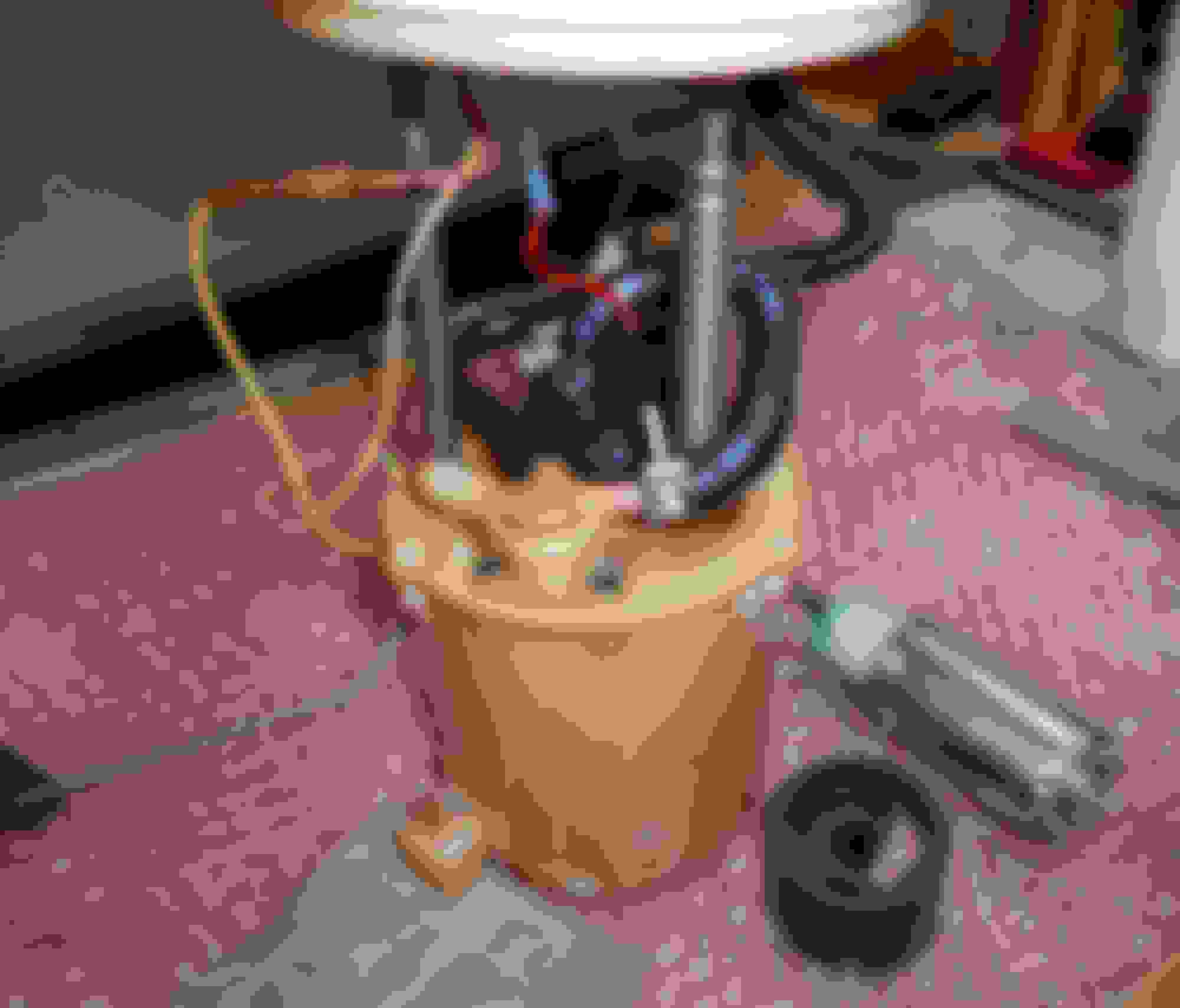
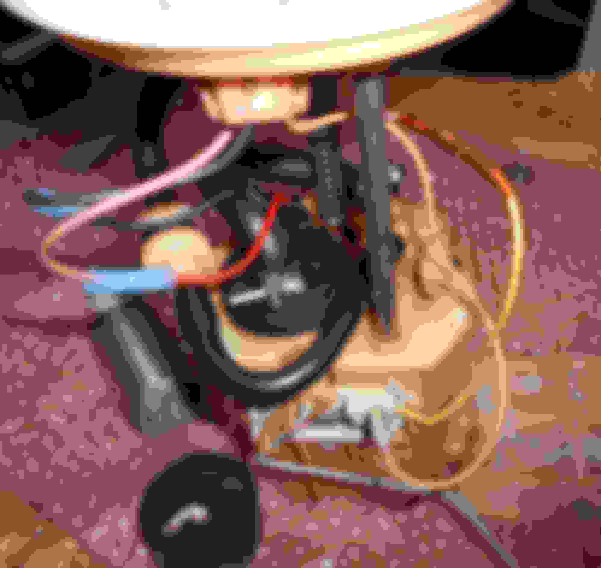
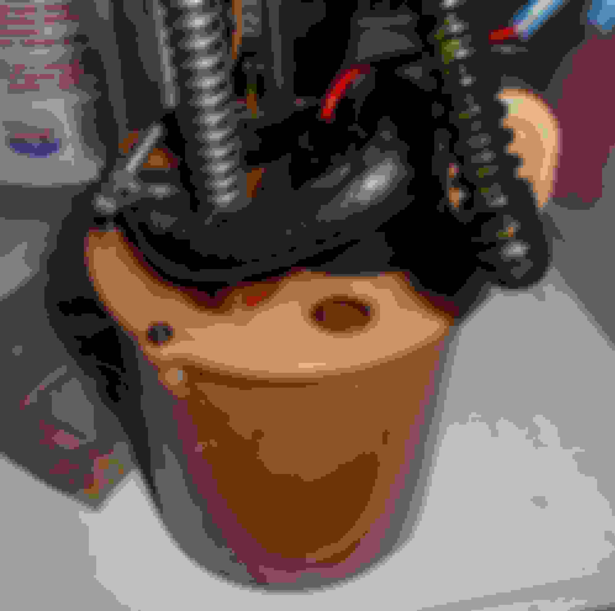
New pump fitted, old pump shown. From another ngle From another angle Hole for hose end ? One hose obviously fits barb, other just drops into hole ?
IIRC: The other hose connects to one in the tank which comes from the other side of the saddle tank and is from the 'jet pump' assembly that transfers fuel to keep it level on both sides of the saddle. The 'jet pump' assembly also accommodates the level sender on the other side of the tank. From many hours of having my hands in my fuel tanks I think you must reconnect this after having carefully put the fuel pump housing back in the tank, taking great care of the delicate level sender arm when you're going through the hole.
Attached is a schematic of your fuel system taken from the X350 technical guide. This is available somewhere on this site I think. Its too large a document to attach but it contains a lot of useful explanation of the different systems that the workshop manual does not.
If you think the NA fuel system is overly complex and un user friendly, you should look at the duel pump set up of the early XJR's!
Thanks Paddy,
The diagram of the tank is useful.
Not sure I understand how it works, it seems odd that the high pressure pump outlet supplies the engine fuel rail plus it recirculates high pressure fuel back to its own pump canister and also across the saddle to the other half of the tank.
How does it avoid the extra two outlets bleeding off into a low pressure area also dropping the pressure to the fuel rail ? The diagram does appear to mimic the pump setup for my car.
I always thought there was another pump in the LH half to transfer fuel over to the RH half.
Looking at the "Jaguar Manual For Cretins" there is a line drawing of an NA tank for VIN 442 to 45703 which mentions a "Fuel Pump Module" in the RH side and a "Fuel Transfer Pump" in the LH side.
That does not agree with the diagram from Paddy, but I do not think the manual is 100% correct with some tank related operations it describes
Below is the text explanation of the fuel system in the NA models from the same Jaguar X350 Technical Guide. The fuel pump is variable speed, driven by a PWM signal from the engine ECU which matches fuel delivery to the demand from the engine. The transfer of fuel from one side of the tank to the other uses a venturi jet to induce flow in the crossover pipes. The only models with two fuel pumps are the XJR's up to 2005 I think. Then the XJR's went to a single pump like the NA models, although the pump was a higher capacity unit I think. The 'Fuel Pump Module' your document refers to is a bucket assembly just like the other one but it has no fuel pump in it, just a venturi jet to transfer fuel from one side of the tank to the other
Fuel Tank and Lines Introduction The XJ Range features a new fuel system incorporating a saddle tank positioned underneath the vehicle. A single fuel-pump located inside the tank on normally aspirated vehicles, provides optimal fuel-delivery performance. The flow-rate requirement of supercharged vehicle is achieved by the employment of a twin-pump fuel delivery system. The addition of an electronic returnless fuel system is also a further enhancement to the system. Key Data
• Fuel tank capacity:
- normally aspirated 85 liters (18.7 gallons),
- supercharged 84.5 liters (18.6 gallons).
• Fuel rail pressure: 3.8 - 5.0 bar referenced to inlet manifold pressure.
• Maximum fuel flow - normally aspirated: 120 liters/hour at 3.8 bar (to atrnosphere).
• Maximum fuel flow - supercharged: 180 liters/hour at 4.8 h:cir (to :citmosphP.rt>. Fuel Tank
To optimize luggage compartment capacity the fuel tanl< is now positioned underneath the vehicle, below the rear seat. This positioning necessitated the installation of a saddle tank to allow the vehicle's driveshaft to pass through the arch of tank. The tank is constructed of high-density polyethylene and is retained by two metal straps attached to the vehicle's underbody. A heat shield fitted to the underside of the tank isolates the tank from exhaust heat. Fuel Delivery - Normally Aspirated Vehicles
The fuel pump is a variable-speed rotary-vane type, which operates in a fuel module located in the right-hand fuel tank compartment. /\ fuel transfer module is located in the left-hand compartment; refer to Fig. 70. Both components are secured by screw-on plastic closure rings and have integral top plates for external line-work and electrical connectors.
The fuel delivery line connects to the module on the right-hand-side of the tank. The line has a revised diameter and route, with the fuel filter situated underneath the vehicle's floor on the left-hand side of the vehicle.
Fuel is maintained at an equal level between the fuel tank compartments by circulating the fuel through internal crossover lines via suction jet-pumps. High-pressure fuel from the fuel pump is directed through the jet-pump's orifice,
creating a low-pressure area to be formed around the orifice. Fuel is drawn into this low-pressure area and directed into the crossover line to the opposing module.
Fuel is pumped from the fuel pump to the fuel rail via the parallel pressure relief valve and fuel filter. The parallel pressure relief valve contains two spring-loaded valves, which operate in opposite directions. The function of the valve is to:
• Assist engine starting by retaining a pre-set fuel pressure in the fuel delivery line and fuel rail.
• Limit fuel-rail pressure due to temporary vapor increase in hot conditions.
• limit fuel-rail pressure caused by sudden load changes for example, a fully open to closed throttle transition.
• Prevent leakage from the tank in the event that the fuel delivery line is severed.
The pump is back in the tank.
As mentioned earlier I replaced the short life span OEM pump with a Bosch Universal.
Not an easy job to do that, the design of the pump module essentially makes it a non repairable item.
My stepson is taking over the car and his mechanic friend put the pump back in for him.
He says the fuel gauge is stuck on half full so not sure if the two sensors are wired in series or they have separate outputs summed electronically.
Not a big deal because the car will be a weekend driver and he can easily calculate the fuel in the tank any time.
I did not find any hits on Ebay for E2226 just now.
Lots of other pumps including for various Fords at $50 and upwards.
You are correct a pump which is a direct replacement fit, but not from the OEM supplier, would be a great help.
Using the number of the OEM pump gave no Ebay hits either.
However, seeing that the last OEM pump died at 55,000km not sure I want aother dose of that.
ford in-tank pumps are always sold as units, this is standard procedure. the number printed on the side of the motor is the engineering number. the OE supplied pump can be bought separately as jaguar part c2n3866 for the x308. only 322 us bucks.
Resurrecting this thread because I just replaced the fuel pump in the housing and I'm having a heck of a time getting the lines routed back to the Left side (looking forward) of the vehicle while installing the pump assembly (in the right side). It feels like I am applying more pressure than is reasonable to the assembly to get it installed and aligned in the hole and when it is, the lines fall short of the sender on the other side. Does anyone have any guidance they can offer for routing of the lines? Thanks for any assistance.
Going to have to reach your arm through to grab the lines, then pull them back through.
While having another person pushing it to you.
We used some 1/4" flexible coper tubing for the pushing.
Next time tie some stout string on to pull it back through.
Seems they left this step out of the instructions
Hey Wingrider, thanks for the reply. I did attach some OEM stout string to the lines attached to the old assembly, but having a devil of a time getting it pulled back through. I'm flying solo at the moment, which makes matters all the more challenging. I do think I'm going to have to get my hands in there like I'm birthing a cow and have syphoned the tank in preparation for such fun and high jinx. Any other tips for routing of the lines? It seems as if they may be kinked in the tank. As I pull on the string, the pump assembly turns in a clockwise direction (which surely can't be right). Any help is appreciated. Thanks again.

 08-03-2018, 03:50 AM


 .
.