Early 93 USA Vanden Plas 671330 brake boost not switching on
#1
Early 93 USA Vanden Plas 671330 brake boost not switching on
I can jumper the ABS relay and the pump turns on.
The pressure switch shows continuity at low/no pressure between pins LS2-1 WN and LS2-4 YP.
Reservoir full
Brake hazard light is on
ABS light is on
Does this suggest Combined Pressure Switch failure or ABS module failure?
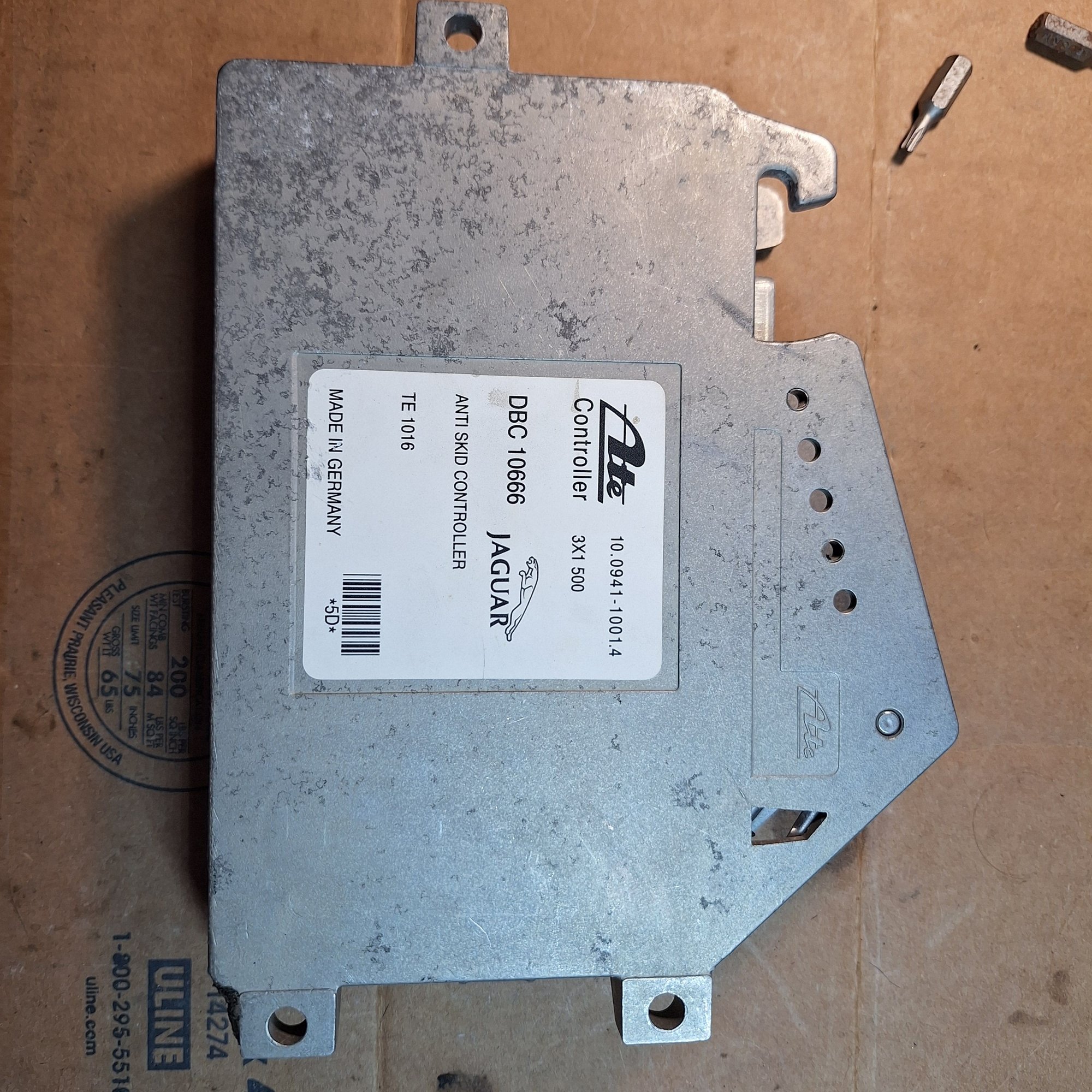
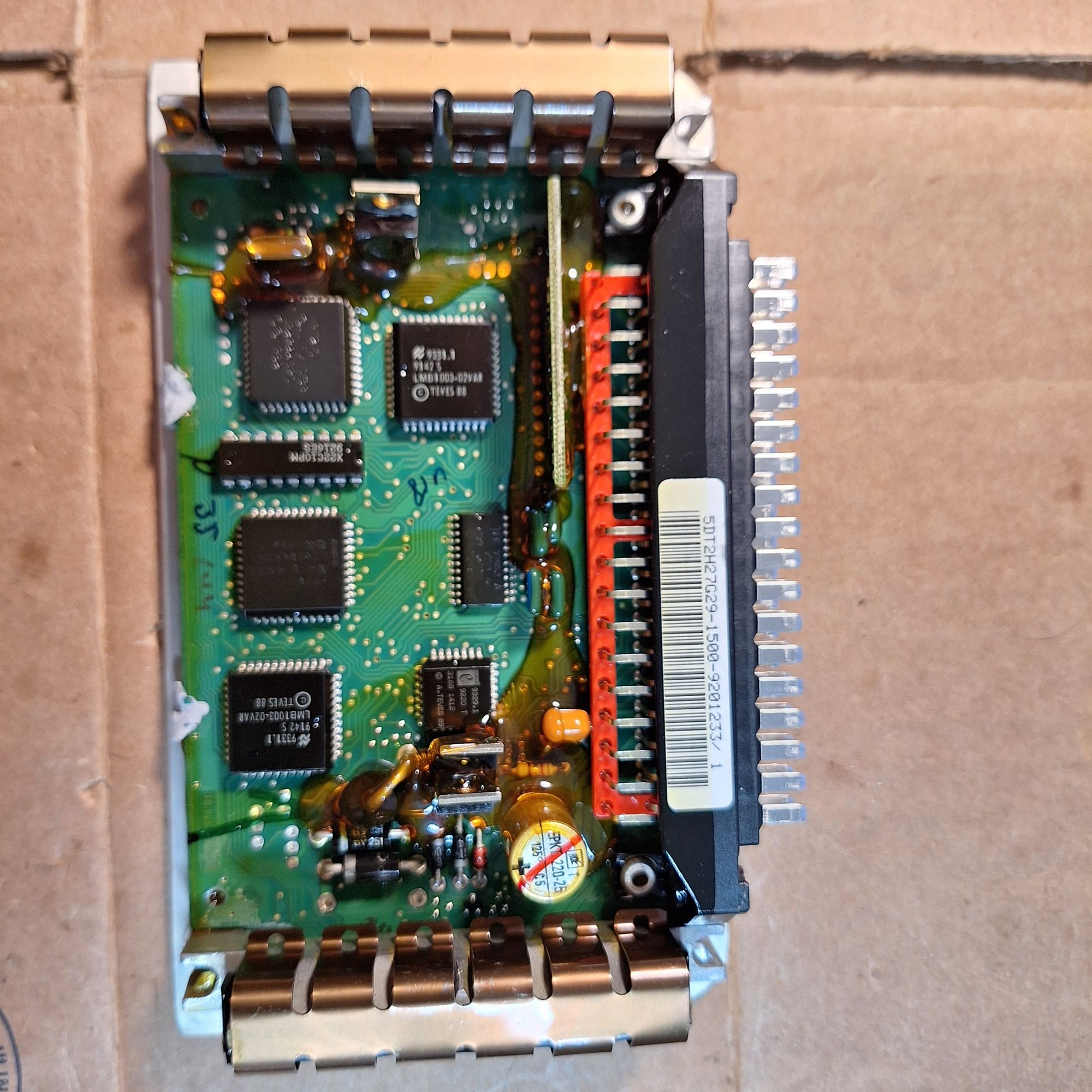
How does the ABS board come out of the housing seeing as all 6 torx screws are removed but it doesn't want to budge?
#2
The following users liked this post:
Don B (07-03-2024)
#3
Pressurizes fine when I jumper the relay, it's something in the control side. I've been having endless electrical failures in this chassis, resoldering boards, replacing components, every day a new failure. I'd love an aftermarket/dirt track racing solution that bypasses the factory BS and just gets this effing brake system braking w/o ABS. I finally get the chassis sorted and the electrical turns it into a no show.
#4
Join Date: Feb 2014
Location: Crossroads of America
Posts: 19,558
Received 13,107 Likes
on
6,531 Posts
Hi 87octane91,
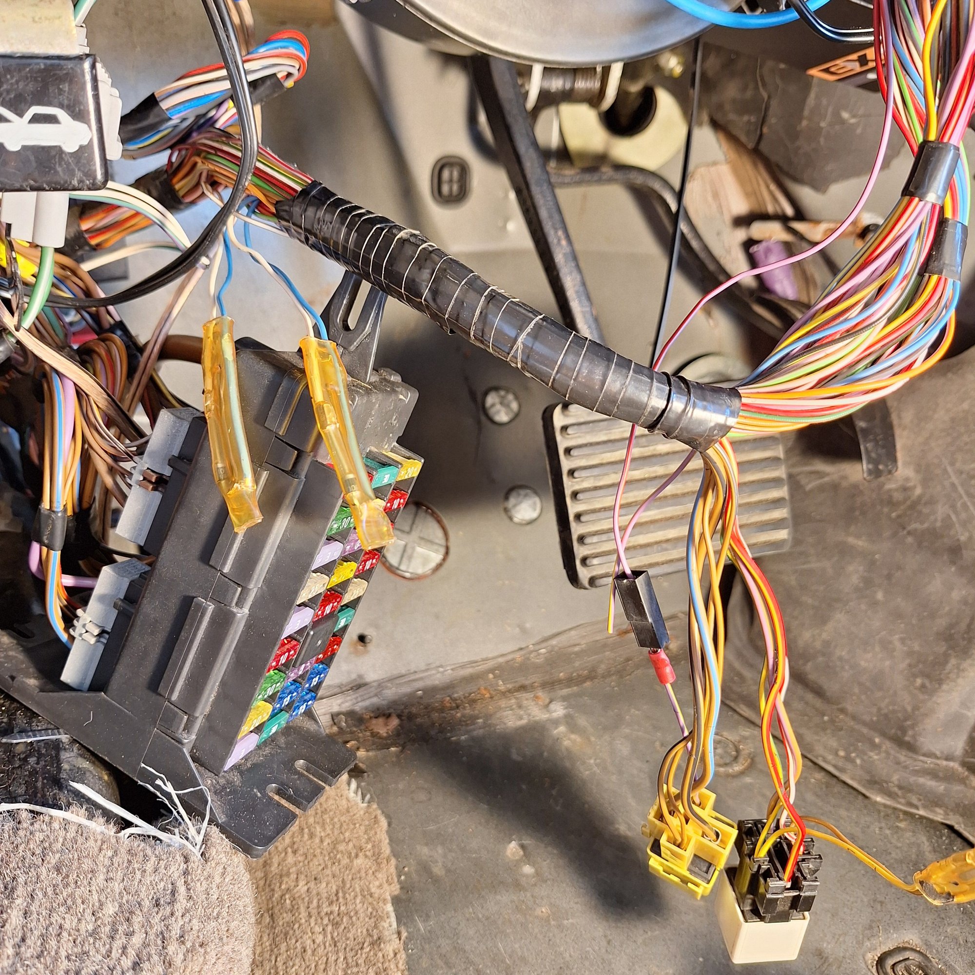
It's been awhile since I had to deal with the brake hydraulic system in our '93 VDP, but at one point the combined pressure switch failed in the circuit that powers the pump, and after searching unsuccessfully for an affordable replacement switch, I ran a wire from the pump relay to the center console and zip-tied a small push-button switch to the hand brake handle so when the BRAKE warning light illuminated, I could just press the button and run the pump until the light extinguished. We drove it that way for a couple of years, until I found a good replacement combined pressure switch for less than nuclear submarine part prices.
I am attaching some relevant documents that may be helpful in diagnosing your issue. I also have the Brake section of the Workshop Manual but it is too large to attach to a post. If you don't have it, send me your email address via Private Message and I'll send it to you. The file size is around 48 MB.
Based on your symptoms, it sounds like the combined pressure switch is working in the circuit that powers the pump when pressure is low, and in the circuit that illuminates the low brake pressure warning lamp. The third circuit in the combined pressure switch communicates with the brake fluid level switch in the reservoir. Have you tested the fluid level switch for proper operation? With the fluid level full, there should be continuity between the White/Green wire and the Purple/Green wire.
P.S. If it turns out that you do need a combined pressure switch, I may still have a good working one.
Cheers,
Don
#5
Don, you truly are the lost library of Alexandria Egypt, please never ever die.
As of this moment, I have continuity from the reservoir switch across pin 1 LS19-1 WG to pin 2 LS19-2 PG (from the combined pressure switch)
Pin LS2-5 WU to LS50-51 (in the ABS module) reads open at low/no pressure. At full pressure with 1 minute of pump run time, there is continuity from LS2-3 to LS2-5 WU to LS50-51 in the ABS module, suggesting the combined pressure switch is still good.
The ignition switch ground 11 has other circuits working just fine, thus presumably eliminated.
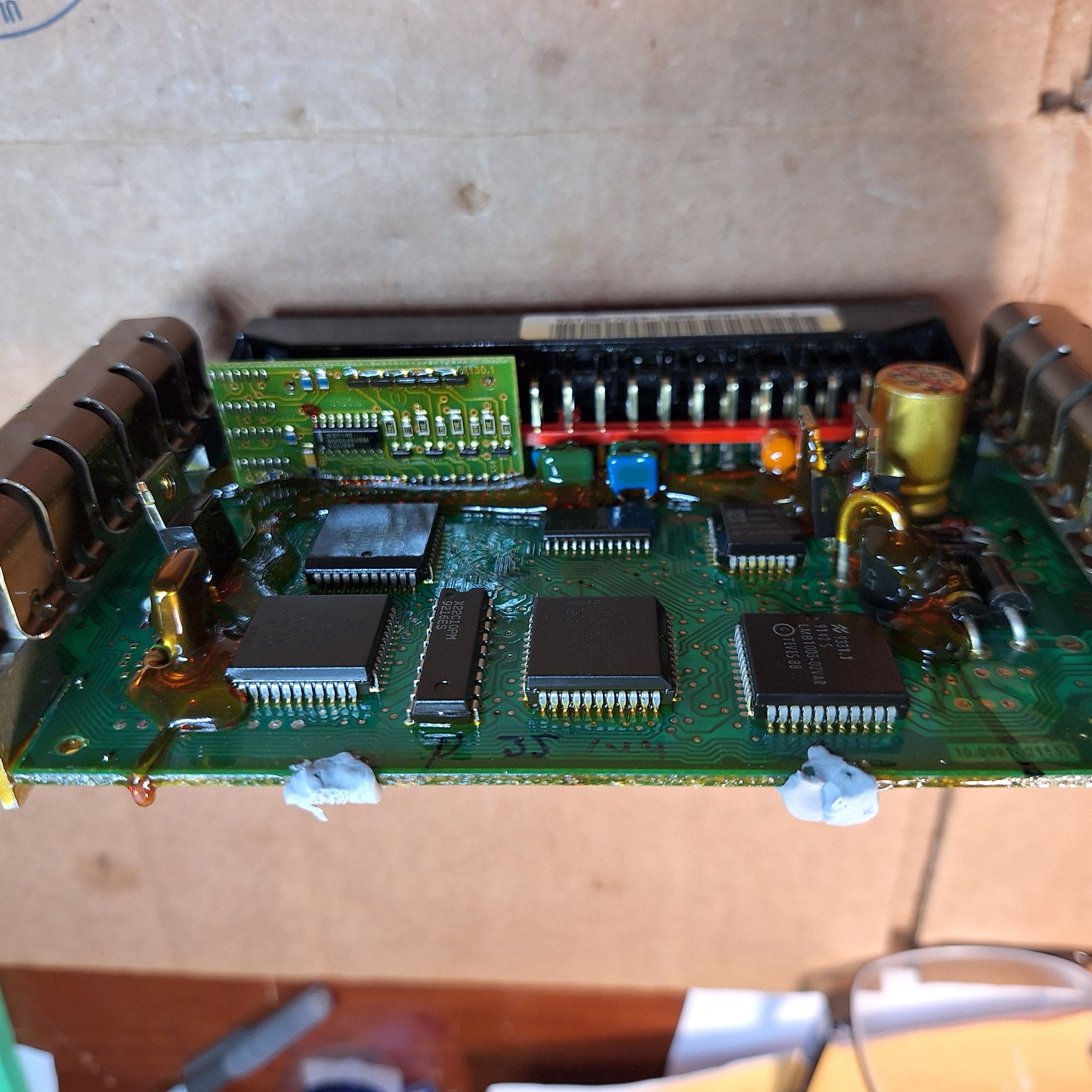
I still can't figure out how to rip the ABS board out of the housing to inspect. I assume it's glued together like so many other components in this rig.
What have I missed?
The following users liked this post:
Don B (07-05-2024)
#6
Join Date: Feb 2014
Location: Crossroads of America
Posts: 19,558
Received 13,107 Likes
on
6,531 Posts
On most of the ATE ABS modules the cover is glued or ultrasonically welded to the case, so to open it you have to saw a thin shallow kerf all the way around the cover, taking great care not to saw into the circuit board. Once the cover is off, the solder side of the circuit board is accessible, so you can inspect for cold, starved and broken solder joints.
Try to find photos online specifically for the late XJ40 module. I don't think I've ever had to open one, but I have opened lots and lots of the ones in the X300s and X100s/X308s, which are notorious for bad solder joints.
#7
Join Date: Feb 2014
Location: Crossroads of America
Posts: 19,558
Received 13,107 Likes
on
6,531 Posts
Octane,
I am posting these thoughts from our PM exchange in case they prompt any ideas from other members that may help you get to the bottom of your brake malfunction:
I note this presumption from your Post #5. I would suggest testing the resistance between the White/Brown wire at the combined switch connector to a good ground.
Also, looking at the schematic, there are two diodes in the Yellow/Purple-White-Blue-Brown/Black wire series that connects LS2-4 at the combined switch with terminal 86 of the pump relay. If one of those diodes failed, battery power from 21 might be grounding through the switch instead of through the relay coil, preventing the relay contacts from being pulled closed. If your meter has a diode test function, you can test this theory. My assumption is that the diodes will be wrapped in the harness near the splice shown on the schematic. The diode that failed in our '93's fuel pump harness was just crimped to the harness wires and covered in heavy heat-shrink tubing.
I can't remember if you reported testing the conductivity through the switch contacts when the system is pressurized, but that should tell you if all the contacts inside ths switch seem to be responding correctly.
Cheers,
Don
I am posting these thoughts from our PM exchange in case they prompt any ideas from other members that may help you get to the bottom of your brake malfunction:
Also, looking at the schematic, there are two diodes in the Yellow/Purple-White-Blue-Brown/Black wire series that connects LS2-4 at the combined switch with terminal 86 of the pump relay. If one of those diodes failed, battery power from 21 might be grounding through the switch instead of through the relay coil, preventing the relay contacts from being pulled closed. If your meter has a diode test function, you can test this theory. My assumption is that the diodes will be wrapped in the harness near the splice shown on the schematic. The diode that failed in our '93's fuel pump harness was just crimped to the harness wires and covered in heavy heat-shrink tubing.
I can't remember if you reported testing the conductivity through the switch contacts when the system is pressurized, but that should tell you if all the contacts inside ths switch seem to be responding correctly.
Cheers,
Don
Last edited by Don B; 07-30-2024 at 09:52 PM.
Trending Topics
#8
Don's "hotwire the relay with a switch" workaround got the car back on public streets and I was successfully able to panic brake at 70 mph on a deserted back country road. Noticing the switch connector unplugged and plugging it back in (Doh!!) made the ABS and Brake dash indicators behave normally, giving me hope the combination switch on the accumulator is good, but saddening me that the ABS module may be fried. However, didn't have time to test the diodes hidden in the harness due to other test priorities. (Such as the Dukes of Hazard bonzai run down a dirt road filled with potholes to test tire to body clearance. Totally stoked to report no contact, no carnage! 245/18 fr 275/18 rr FTMFW!)
In honor of all the miserable electrical problems this hulk has tormented me with, I hearby rename "Leaky Bucket" to "Madame EMP" (electro-magnetic pulse nuclear weapon for you non-military out there). EMP's christening ceremony shall consist of short drive to DMV to get legal and pin on her first badge of classic license plates with the blue on yellow scheme current when the XJ40 was first released. Old school cool without the spendy Historic Vehicle money makers DMV wants to sell.
In honor of all the miserable electrical problems this hulk has tormented me with, I hearby rename "Leaky Bucket" to "Madame EMP" (electro-magnetic pulse nuclear weapon for you non-military out there). EMP's christening ceremony shall consist of short drive to DMV to get legal and pin on her first badge of classic license plates with the blue on yellow scheme current when the XJ40 was first released. Old school cool without the spendy Historic Vehicle money makers DMV wants to sell.
The following users liked this post:
Don B (07-29-2024)
#11
The following users liked this post:
Don B (07-31-2024)
#12
Pulled both fuseblocks and removed the boards. Unable to separate the two with various soldering irons and heat guns, but the visible sides showed no problems with the solder. Burnt around the radiator fan fuse socket, but the fans work. No photos, sorry. Back to under the hood.
Ground test: Pin 1 on the 5 pin connector to combo brake switch on the abs pump/accumulator goes to ignition switched ground. It tested open when key off and grounded when key in position 2, but open when key in position 1 (accessory), contrary to the 93 schematic for key switched ground. Meh, doesn't seem to bother anything.
Reservoir full/low switch is pin 3 off the combo switch. There's fluid, reservoir switch shows continuity. On to the Combo switch now.
Combo switch-no pressure. Continuity from pin 4 (relay) to pin 1 (ground). No other pins go live. So far, so good.
Pump 'er with the Don hot wire till the lights go out. No continuity 4 to 1. But yes on 3 (reservoir) to 5 (abs controller) and yes on 1 to 2. Looks just like the schematic to me.
So that looks like the relay works, the combo switch works, reservoir switch works, abs main board does not look fried, switched ground is good.
Lunch and more worshipping of the schematic. Relay trigger goes from purple/yellow to blue to diode to white to yellow/purple to LS12 "NOT USED" before getting to the combo switch. What TF and Where TF is this stupid "Not Used" LS12 connector hiding in the chassis/harness/universe? And has it corroded, gotten wet, grounded, or **** all?
Back to the snipped purple/yellow under the dash and continuity check to yellow/purple pin 4 under the hood and OPEN!!!! How much ya wanna bet "Not Used" has been laughing at me sweating my *** off for hours in the hot sun, like a bad Netflix sci fi horror plot? Quick pull some 16 guage from dash through firewall to abs pump, snip, strip, crimp, key on and glorious buzz, buzz, buzz, and brake pump shuts itself off when the lights go out on the dash.
Good, now I can re-purpose the hotwire switch to something useful and James Bond- like, a missile launcher perhaps.
Lessons learned: we want to blame components, switches, major electromechanical parts, and controllers. But just like GM wiring from the last 25 years randomly failing somewhere in the chassis, Jag wiring must be considered suspect as well.
Other lesson learned: Stupid Oregon won't let me use old classic license plates except on historic or special interest registrations which are car show only, no daily driving. So in order to keep Johnny Law off my *** on a blast to the coast, I've got to run boring issue plates like every Honda CR-V on the road (every 2nd car). This is the last area of the West Coast with no smog check but they've managed to ruin it anyway. Now, if you'll excuse me, I've got an interior to reassemble. (Where the **** are those console screws?!?!)
The following users liked this post:
Don B (08-01-2024)
#13
The following users liked this post:
Don B (08-01-2024)
Thread
Thread Starter
Forum
Replies
Last Post
Donald ThaDon Masson
MKI / MKII S type 240 340 & Daimler
1
09-22-2017 12:15 AM
Currently Active Users Viewing This Thread: 1 (0 members and 1 guests)


