When you click on links to various merchants on this site and make a purchase, this can result in this site earning a commission. Affiliate programs and affiliations include, but are not limited to, the eBay Partner Network.
Injector, injector rail, and injector loom project
Some time ago I started this thread https://www.jaguarforums.com/forum/x...wanted-281293/
which set out how, using a cheap pulser from Amazon and a can or two of carb cleaner, I managed to build a good injector spray tester and injector cleaner. Amazingly all 12 of my long-unused second hand injectors worked perfectly.
The overall plan is to have i) refurbished injectors on a ii) cleaned up rail with iii) a new silicone injector loom; all built up off car, ready to fit as a unit. As I am lucky enough to have a spare engine, I removed the rail from it and that is the basis of the project. In that way I can continue using the car until the time the replacment rail and loom is ready, and just swap them over in a morning when the time comes.
My current loom is a replacement from the original; but is over 20 years old. It is not cracking or failing (as it is fixed to the rail not the bottom of the V) but the connectors to the injectors are starting to look cooked, and are very hard to remove to clean the contacts. The current injectors were also refurbed professionally over 20 years ago, and although the front one I tested is spraying perfectly, they must be due for new seals and filter baskets. Hence the idea to get an entire new rail, loom and injector unit together.
The rail:
I removed the rail by cutting the flexibles leaving the spare engine with the injectors still fixed to it. Then using a gas torch I burned off the old stubs of the flexibles from the rail spigots.
A bath of 75% phosphoric acid cleaned off the surface rust. A quick go in Madame's dishwasher to degrease it and then a spray of galvanising silver paint produced this:
The injectors:
The link above shows how they were spray tested/cleaned. The spray they should produce is shown in the attachment to this post: essentialy a dropless fog. I had in stock a Mr Injector rebuild kit which has everything needed to refurbish them following their cleaning and spray testing. The Mr Injector website is opaque and injector refurb kits are hard to find on it, but this is the kit needed to refurb the injectors on V12 5.3 HE engines. https://www.mrinjectoruk.co.uk/produ...ervice-kit-180
They send instructions with the kit and it is straightfoward to do it.
Fitting the injectors to the rail:
This morning No. 2 son and I fitted the refurbed and cleaned injectors to the rail. We used 8 of the 12 I refurbished and 4 factory refurbished ones from RockAuto that I had in stock. Some notes on the flexible hoses that join the rail to the injectors:
the standard length of the flexibles is 50mm, except for the longer two that are for the front injector on A and B bank. These are about twice as long.
the length of the spigots on the fuel rail is 17mm and on the injectors 16mm = total spigot length 33mm.
Therefore between the spigots the hose length is 50 - 33 = 17mm.
We cut the hose length by 12mm in order to reduce the length of the injector hose between the spigots, but leave a 5mm space to avoid vibration.
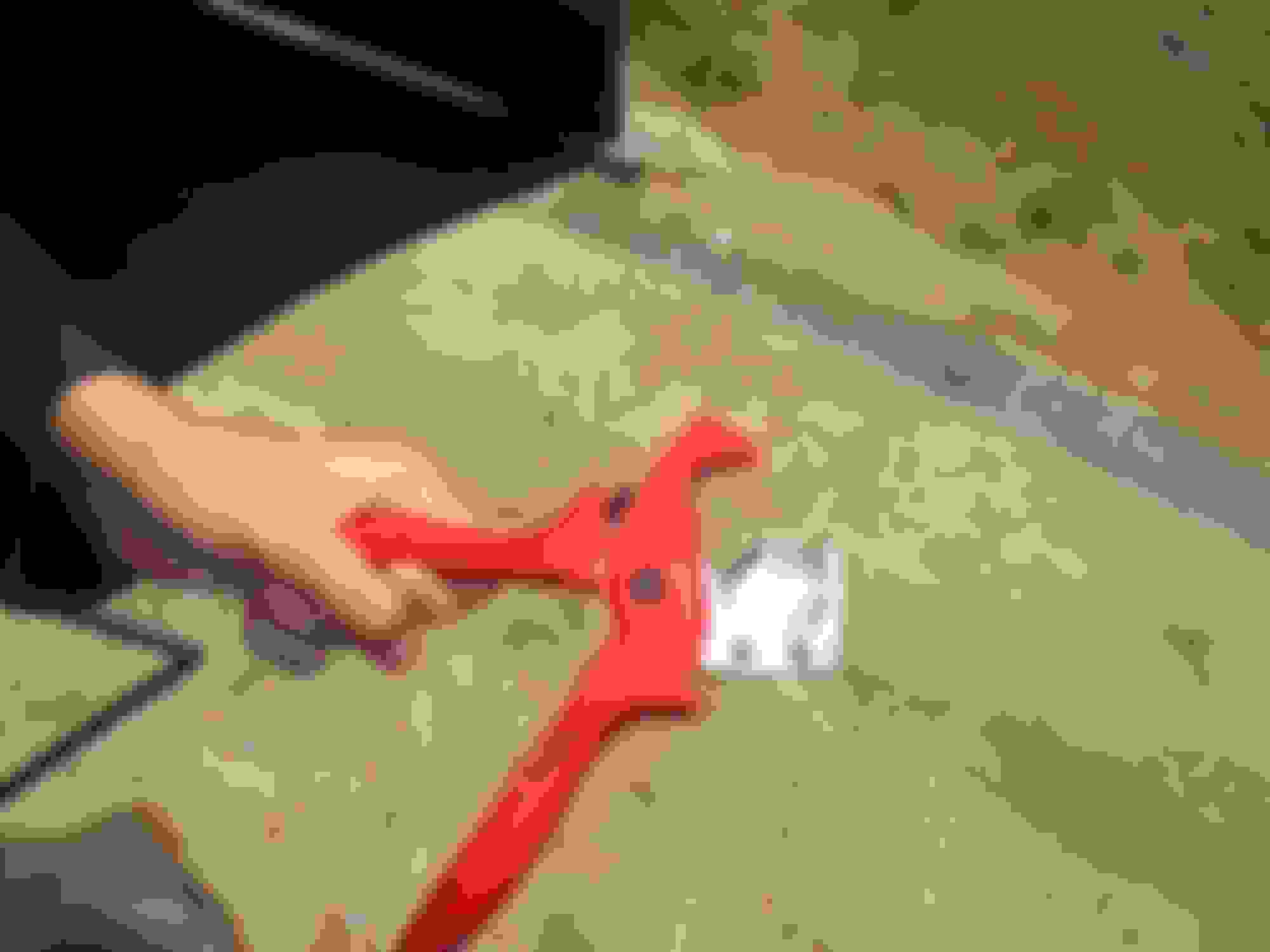
The pupose of this is to aid hot-starting after a hot stop, by reducing the volume below the rail that can contain vapourized rather than liquid fuel. This is a Grant Francis mod (turn and bow to the Southern Cross at the mention of his name) and works in the heat of Australia. Before and after photo here: Yellow line hose standard length of 50mm. Blue line reduced hose length by 12mm to 38mm.
NOTE: the hoses are hard to push over the barbs, we used red brake grease to lunricate the barbs which made it far easier. This type of grease gos not attack rubber
The two long-hosed injectors for the front injector on each bank were also reduced in length by 12mm. The hoses were cut using this superb hole cutting tool which makes a perfect cut: Knipex hose cutting too from Amazon, indespensable if shortening the hoses: https://www.amazon.fr/PlastiCut-coup...85&sr=8-1&th=1
Fuel clips on the hoses, yes or no?
From the Jaguar Factory the hoses had no fuel clips on them to hold them to the spigots, just ferrules at each end (for cosmetic appearance as far as I can tell). Providing the spigot barbs are in factory new condition they do not need hose clips. However they can get scratched when removing the old hoses and can lose their sharp edges. Taking advice from Grant, I decided to fix the hoses as follows:
lightly sand the spigot edges by wrapping a bit of 400 grit paper round the spigot and turning it with medium pressure between finger and thumb. Just enough to make about a 0.5mm flat to the edge of the barb when viewed from the side. The injector spigots had softer steel than the rail spigots, which required more effort. The idea is to ensure that the sharp edge of the spigot barb will not cut into the hose when a clip is used.
then use clips to secure the hose onto the barb. Jubilee clips (ie worm drive clips) are NOT suitable. If you have evened off the barbs as described here, use either fuel clips of Oetiker clips. I have found fuel pipe clips can loosen over time, so I splashed out and bought Oetiker clips and their tool to do them up.
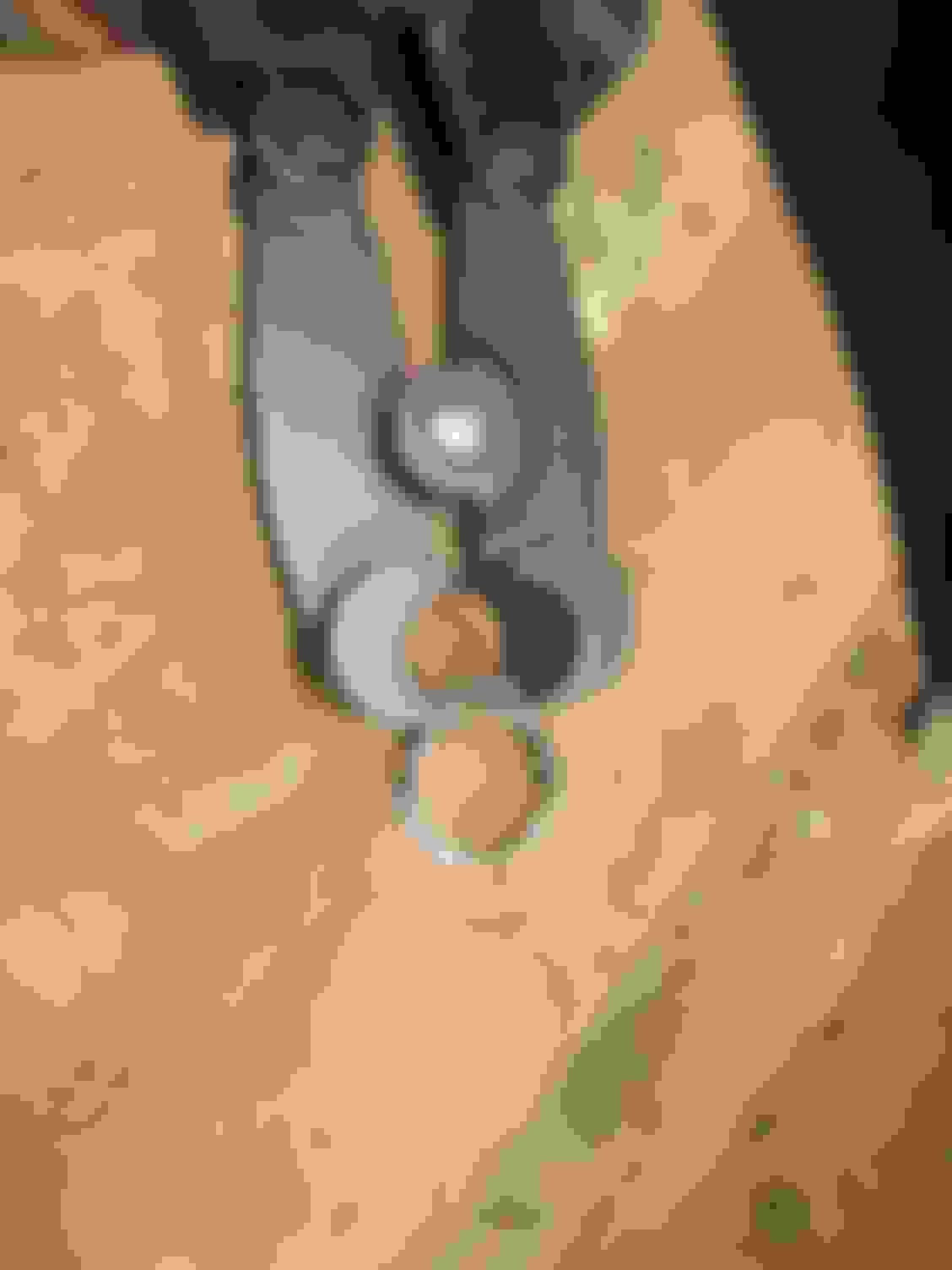
Oetiker clip and tool
Closeup of Oetiker clip on the hose
Injectors installed with clips. Note that the second injector has no clip at the injector end of the hose because it is a new one and came with the hose already fitted to a non-adjusted barb.
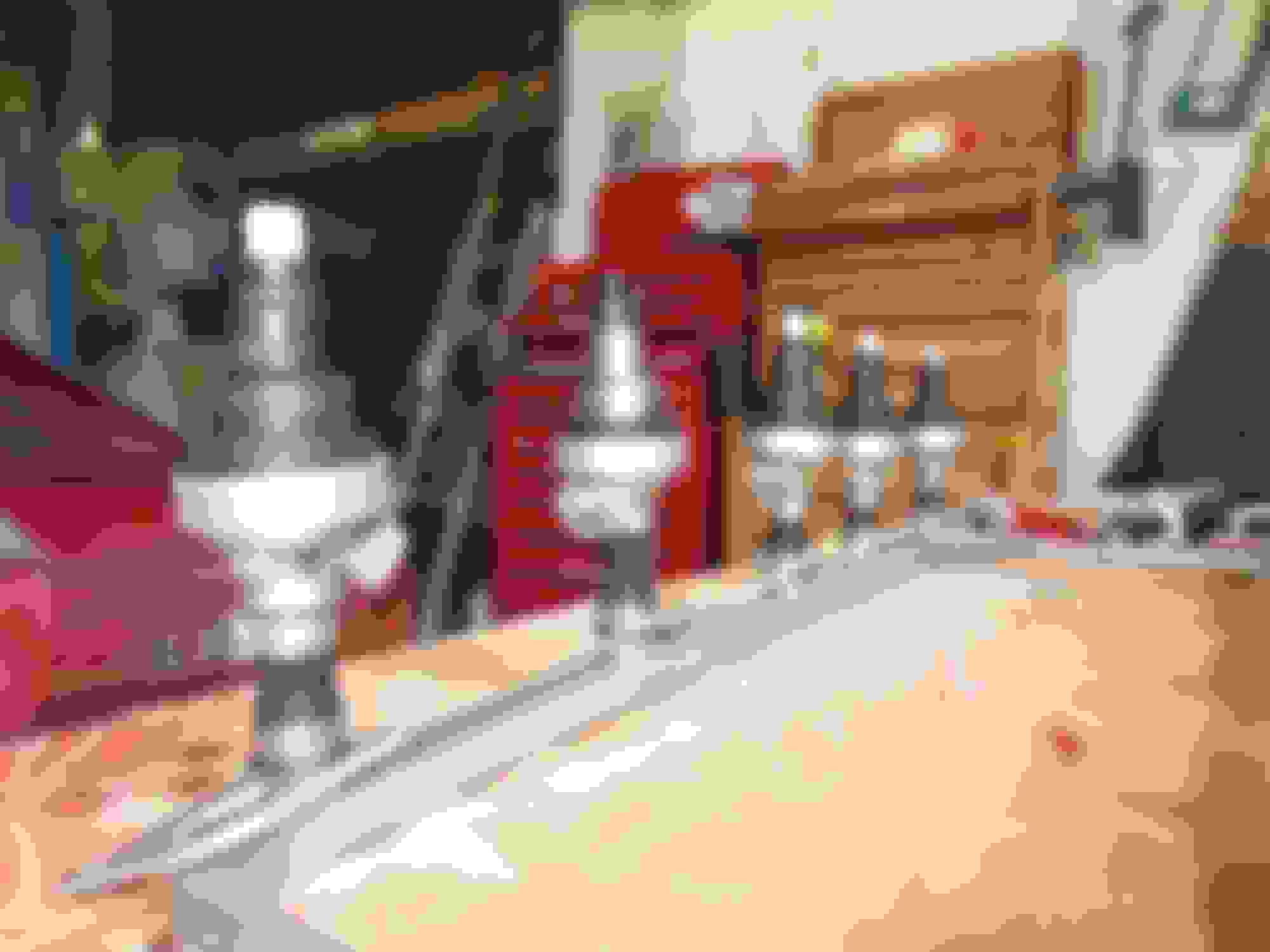
The finished rail and injectors:
Here they are all ready:
A bank done All done
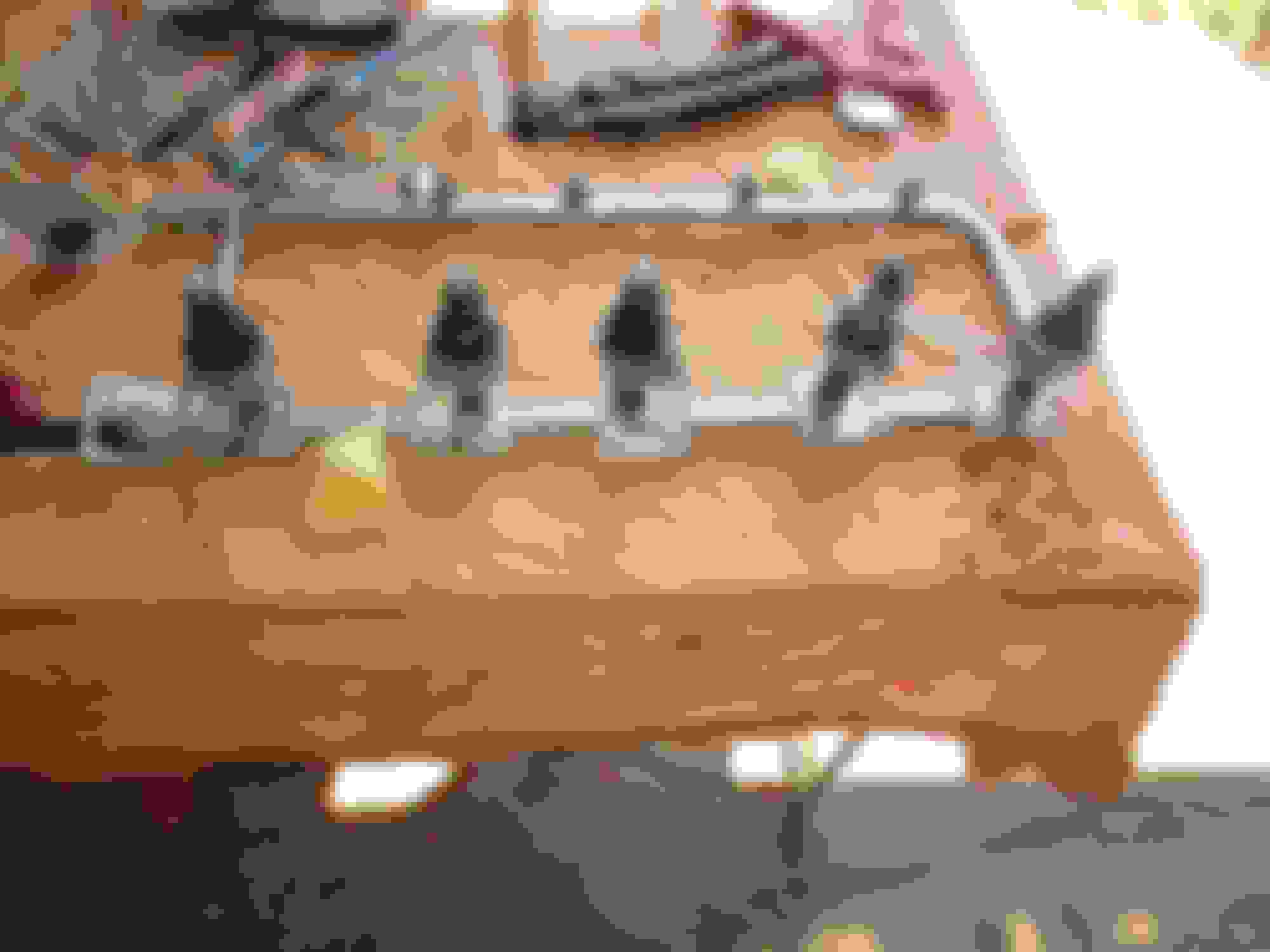
NOTE: The ORIENTATION of the connector moulding male contacts on the injectors is NOT the same down the length of the engine. Therefore great care must be take to ensure the captive fixing collars and the injectors are fitted facing the correct way. This is the factory orientation (A1 is the frontmost injector) but note also: in all cases collars must be fited so that the fixing holes on them face outwards!:
Injector A1 connector facing forward, collar indent to fit connector facing forward Injector A2 As above Injector A3 As above Injector A4 connector facing backward, collar indent to fit connector facing backward Injector A5 connector facing backward, collar indent to fit connector facing backward Injector A6 connector facing forward, collar indent to fit connector facing forward
B bank are the same.
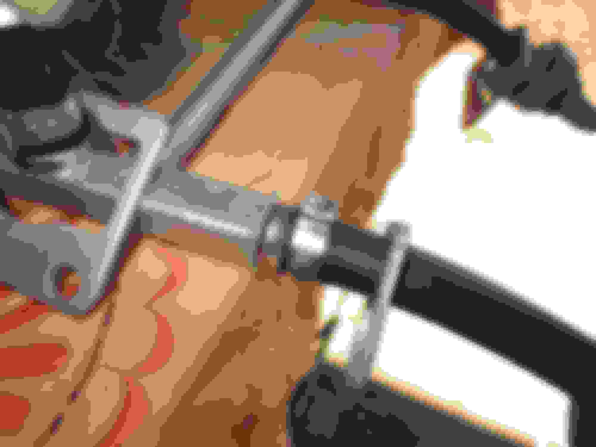
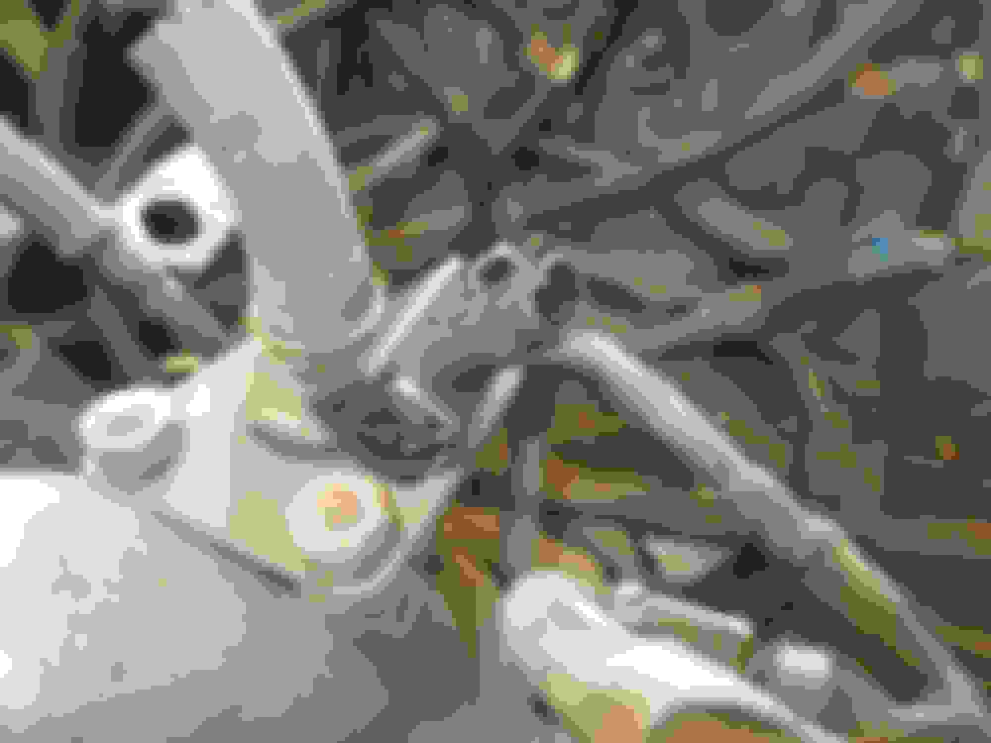
This is injector A1 on my spare engine. Note collar indent and connector facing forward (to the right in the photo). Note fixing holes are outboard of the rail. If making up a complete replacement rail and injectors as I am, the fixiong collars are captive, so the correct orientation of the fixing collars is vital. If you make a mistake you have to remove the injector to correct it!
Loom to Injector conectors:
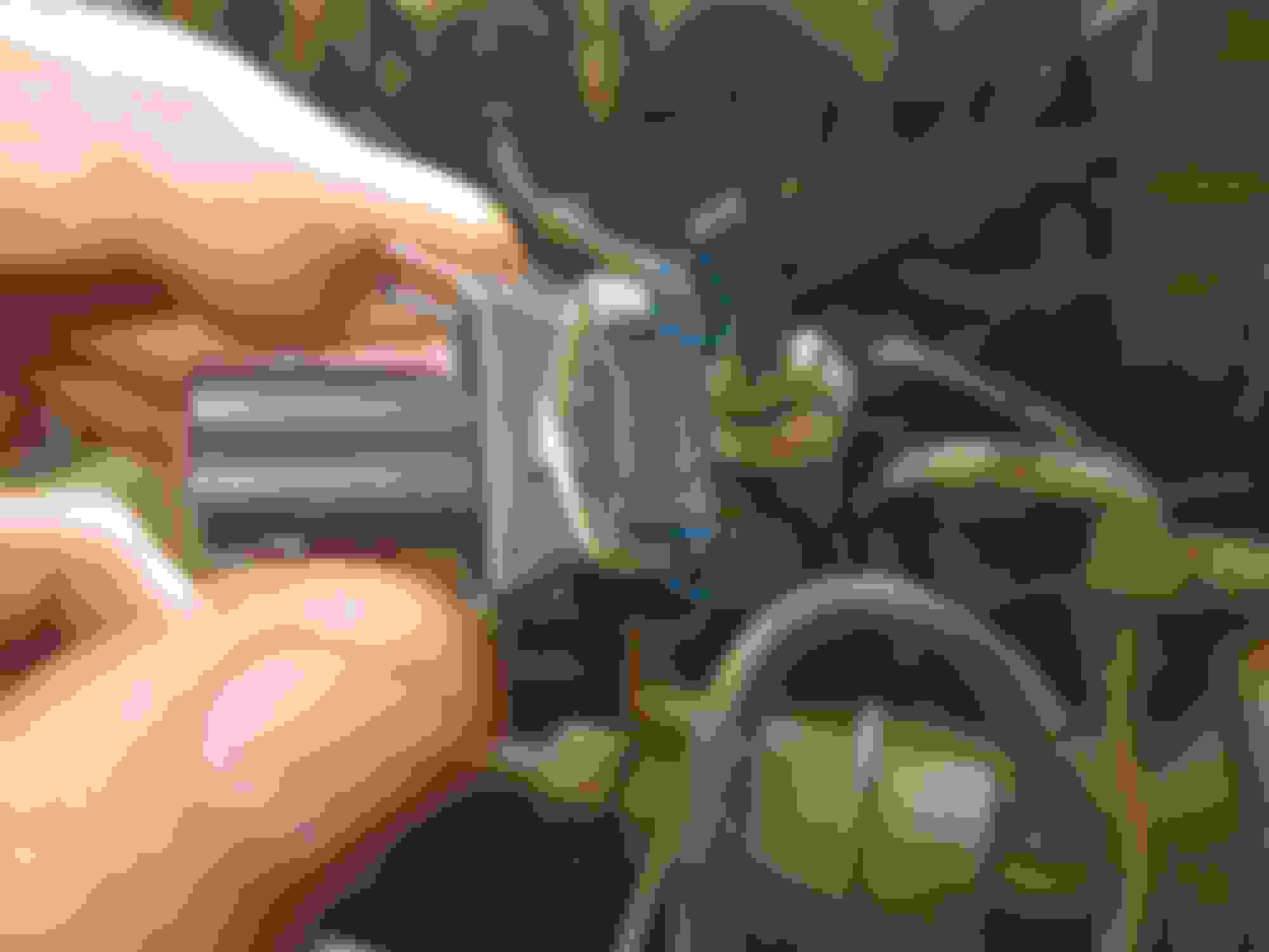
I mentioned at the start that the connectors on my loom are beginning to look past their best, and also are very hard to unclip. When I make my new loom, which will be a couple of months, I will use the clip shown in the photo above. This type of clip has sideways release metal and is FAR easier to remove from the injector to clean the contacts - which is important to do periodically for even tickover etc etc. They need a slight adjustment however, as the corners just foul the fixing collars. I ground about 1mm off the two corners so that they fit easily onto the injector with a confidence-inspiring 'click' without fouling the fixing collars:
Next installment:
In October I will build a new injector loom using silicone insulated wire for indefinite heat protection, and will use the above clips for the injectors. The beauty for me of having the rail and injectors all ready as a unit, is that I can wire up the new loom to the injectors making sure it all fits neatly and properly, with every part of just the right length and with no redundant lengths of wire in the loom.
Thank you very much for this Greg. It is very helpful and will make my future project easier.
One question on the loom. I've taken your advice on sourcing the clips to the injector, but what about the loom to the main harness? Is that a unique fitting? Deutsch? Someone else?
Thank you very much for this Greg. It is very helpful and will make my future project easier.
One question on the loom. I've taken your advice on sourcing the clips to the injector, but what about the loom to the main harness? Is that a unique fitting? Deutsch? Someone else?
The loom to car connector is a moulded type and cannot be bought. If you are making a new loom you have two choices:
cut the connector off the old loom and splice it to the new loom you are making and plug it into the car harness original connector, or
replace the connector on the car loom and the new injector loom you are making.
I have ordered a set of these Deutsche connectors (not used them before) and will repace the OEM connector on the injector loom and the car loom with them. I am going to make separate looms for A bank and B bank, and will use two 4 pin connectors. Coincidentally they were delivered while I was writing this. they seem to be well made. https://www.amazon.fr/dp/B0D21VSW2M?...roduct_details
Each bank of injectors has 2 12v power feeds (one for injectors 1, 3, 5) and one for injectors 2, 4, 6.
Similarly, each bank has 2 leads that go back to the ECU which do the actual switching. One does the switching for 1, 3, 5 and one for 2, 4, 6.
Thus 4 wires at the car to injector loom connector for A bank and 4 for B bank, hence my 4 pin connectors.
BUT, in order to feed three injectors, each of the wires must be spliced into three within the injector loom, so it can be connected to three injectors. I have decided to try these marine grade shrink-fit crimp connectors to do this job:
Time will tell if these work well or not! You will need 8 per bank (two per wire x 4 wires). They will be in effect Y shaped connectors with one arm of the Y going down to the injector and one going on to the next Y connector. Two will give you the three "arms" down to the injectors you need. Hoping you follow!
I also attach Ben Kenobi's great illustrative diagram in word format:
FYI, the main thing with fitting new connectors to the car and loom is to ensure you distinguish the power and the switching leads accurately. The colours are as follows and are easily visible still on the looms:
ALL the power leads are pink/brown (ie mainly pink with a brown stripe - that actually on my car looks like a black stripe). Therefore it does not matter which power lead does to which bank as long as two go to each bank.
The switching leads (called Peak and Hold leads) are coloured as explained in the attached pdf document. Following this should enable the use of new conectors without problems.
Ask away if anything unclear.
 Today, 08:18 AM