When you click on links to various merchants on this site and make a purchase, this can result in this site earning a commission. Affiliate programs and affiliations include, but are not limited to, the eBay Partner Network.
Thanks so much Thermo.
I quite understand, I just wanted to be sure in case I had to take alternative approach.
Looking forward to being able to make a secure connection for a change☺️
Hi Thermo,
the box of tricks showed up the day before yesterday, thank you very much. This stuff looks like it will be really useful for a number of different jobs I might have!
Unfortunately I didmt get to use it straight away as I had planned, as after dropping my son off for his train to college, I got cleared up by a car coming the other way that verred off and front-ended me. Apparently my car 'flipped' amd ended up pointing to a ditch, but I got out at least and was able to move around.
As that was my son's car I'd been using it does mean that I have try and get the old cat back on the road.
I've spent most of the interim sorting insurance etc, but I finally managed to get to the car today if not a bit on the late side.
So I tried to solder up the glow plug cable wires in situ with small blow torch but it was quite knacky and the solder (I tried 3 different reels) didnt really want to stick despite having used electrical cleaner spray and added flux to the wire and solder.
I tried various approaches and got a little blob to take in the end but it was fairly unsatisfactory, though after strong heating I got the blob to melt and level down a bit. Still need to put a whole lot more on it though. It could be the solders internal flux is too old as well.
I might need to use a soldering iron yet but will probably need to borrow mains power from a neighbour unless I bring it across the road, also not sure if it has the heat capacity to solder ot well too.
Will try again tomorrow anyway
Jagalag, atleast you are ok. That is what really matters, right? That looks like it was a hell of a hit. Granted, they hit you head on, so, I am sure that was enough to knock your fillings around a bit.
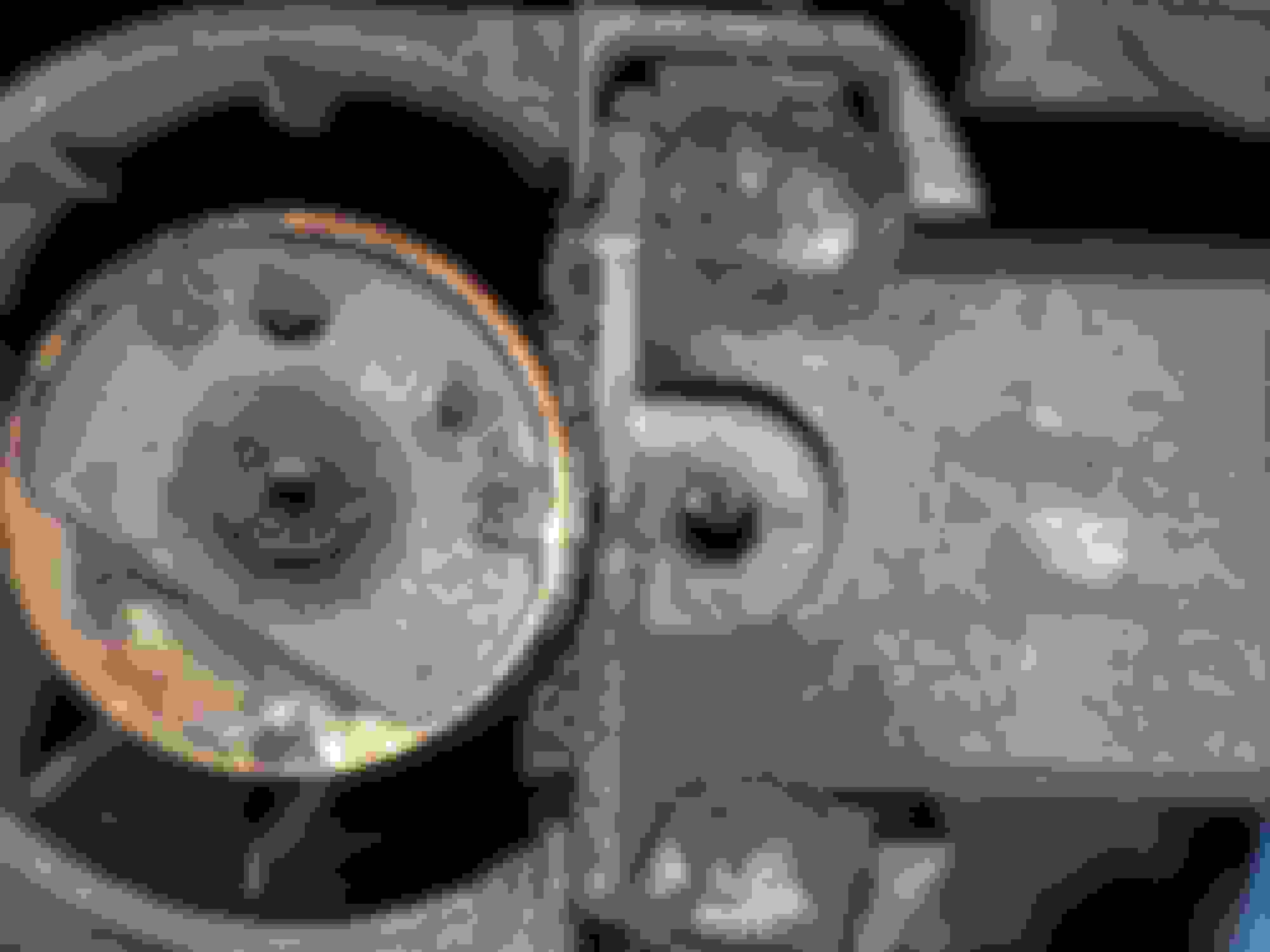
As for the soldering, looking at the one picture, the wire looks like it may have a little bit of oil on it. So, I would try getting some rubbing (isopropyl) alcohol and get as high percent stuff as you can find. May have to go to a pharmacy, but you can normally get your hands on 90% stuff, if you are good, 100%. Granted, the 70% will do, just have to spend a little more time drying. You wll probably also need to use say a 60 watt iron vice only a 30 watt. I would also get a nice wide blade and lay it flat on the wire and then touch the solder to the iron right where it touches the wire. This should get the solder to flow under the blade and help transfer heat. You can then slowly add more and more until the whole wire is tinned. These are the 2 tricks I would be using.
Worst case, get yourself some uninsulated butt splices (going ot look like a metal tube about 2 cm long and need to get it big enough to allow a wire in each end). You can then slide it on one end, use some channel locks or if you have a crimper big enough, use that. But you are going to squeeze one end on to the wire. You can then slide the heat shrink along the wire and you can then slide the second wire in and crimp it. You can then crimp this connector if it makes you feel good, but with the Raychem, you don't have to. You will then slide the Raychem down getting your 3 cm of insulation/Raychem overlap on each side and shrink it down. Should be good to go at that point.
The only thing keeping you from a double speed (you going say 40 and other car going 40 opposite direction = 80 m.p.h. crash), is a tiny white painted line and a mutual agreement NOT to play bumper cars!! Smfh!
The only thing keeping you from a double speed (you going say 40 and other car going 40 opposite direction = 80 m.p.h. crash), is a tiny white painted line and a mutual agreement NOT to play bumper cars!! Smfh!
Glad you walked away.
Thanks Dell Gallery, I got whiplashed and the usual muscle strains and aches, but yes at least I walked away. Strange that you should mention the double-speed scenario 40 + 40 = 80 as that is pretty much what happened (in a 40mph zone), except there was no physical white line (just a badly finished join line as the road had been recently re-laid). Actually the point-of-impact speed might have been nearer to 70mph imo, as I had about 6-7m to react, slap the anchors on and veer towards the verge; the other car careered in on my driving-side nose and their hand-brake at least was yanked up (alleged steering in as well), so the speed and some of the potential collision energy got dissipated but the position of impact was the drivers side corner, so I got an almighty yank foward of my head. There's apparently an ongoing investigation which the police won't update me on yet.
Jagalag, atleast you are ok. That is what really matters, right?
Yeah, quite😁 I'm finally off to hospital A&E (4 days later) as a friend is heading to town (25 miles away). Couldn't get a courtesy car in the end as the insurance case is complicated by the risk of not having definitive fault applied to the other driver as it was their front seat passenger that caused the accident, so everything gets more complicated unfortunately.
As for the soldering, looking at the one picture, the wire looks like it may have a little bit of oil on it.
Actually thats most likely to be a combination of melted and burnt flux that I added to the wire to try and get flow on the solder blob. The flux melted and ran down the wire in to the insulation sheath where it bubbled and burnt from the extra heat I had to apply via the blow torch (on low cone flame).
This resulted in a resinous coating over the wires which I did rub off a bit, before using a alternating application of acetone and meths to clean the wire back down with. Pretty awkward though due to the space available
You will probably also need to use say a 60 watt iron vice only a 30 watt. I would also get a nice wide blade ..These are the 2 tricks I would be using.
Yeah definitely, though I have decided to use a combination of crimping and soldering as getting a hold of powerful enough soldering iron and possibly having to move the car.
Worst case, get yourself some uninsulated butt splices (going ot look like a metal tube about 2 cm long and need to get it big enough to allow a wire in each end).
As I already have that butt-connector I was given with the plastic insulation that I stripped off I used that. I then discovered I had a few 'naked' ones in one of my components boxes anyway I used the butt-connector with the yellow plastic still attached at one end for easier handling. Insert pic with extras of the same size
You can then slide it on one end, use some channel locks or if you have a crimper big enough, use that. But you are going to squeeze one end
I crimped using standard 'ovoid' insulated-connector crimps on to the red 'glow-plug side' wire as I had intended to put the shrink tube (6cm) over that as it had more length to slide down, though still not a lot - possibly 8cm at most. However after seeing that it would not probably sit down far enough from the joint where I was of I ended up removing the plastic locating holder on the other wire and put the shrink tube on that side instead.
I then put a bunch of small solder wire offcuts in the crimped butt connector before putting the other wire in and crimping it down as well. The top of the shrink tubing was down about 4cm from the connector - 1st pic in the seq shows the solder pieces I put in the connector - just about discernible
I then used the blowtorch on as low a flame as possible to try and apply solder and melt the stuff I'd put inside the connector. It was quite a big of effort as the solder blobbed and I tried to avoid it heating up the solder length and causing the working end to fall off, which it did quite a bit and then applying a string heat to the connector to get it to flatten down. Crimped connector - blobbing solder and charring insulation
The insulation charred a bit due to the heat require to melt the solder but it didnt really do a lot either. I didn't use any flux and hoped the solder I put inside might have at least melted and adhered to some of the copper - who knows.
Unfortunately it heated up the wire enough lower down to cause the Raychem to shrink down to clamping half way down its length.
I managed to pry it off the insulation/conduit and drag it over the joint Repositioning Raychem tube
So I cleaned the wires again with acetone and meths and got the tubing shrunk down using the blow torch until the red glue oozed to a ring.
I cable tied the finished product over the insulated part of the shrink tubing (rather than over the butt connector or wire) to reduce the possibility of heat or 'wear' causing an issue in the future. Also, put cable holding clip back on (after opening the strap latch up) and used another cable tie on the back prong to hold that in as it had worn down and could move in and out of it's securing hole. Finally, 2 more small cable ties on the main mounting bracket between the shrink tubing and the metal where the contact was quite tight and to reduce potential wear again. Cable tied over the insulated wire part of glow plug lead and the cable holding clip prong
Then I ran a test after I'd put everything back together except the engine cover so I could feel any potential heat in the glow plug cable in case the contact was not solid enough ..which of course I was not expecting to be the case.
The engine tested well, no heat in tube and I tested the lights on auto and manual and all looked good.
Then I voltage-tested the (smaller) loan battery which I had got from the crashed car which the fire brigade had removed on crash day (as my neighbour had taken his one back for his other car)
The battery is the same capacity and CCA as his one too.
I had 12.45V before putting.
Then 12.42V when connected and the doors unlocked, but all doors closed.
Then after the operation, with the engine off, auto /manual headlights dropping voltage to 12.36V
With the engine running
No lights 11.88V
With headlights 11.45V
Engine switched off no lights 12.22V
Engine disconnected 12.25V
Engine running time about 8 mins
So it seems clear I have a charging problem. It was getting dark and cold at that point so I didn't pursue anything further. I disconnected the baytery afterwards. So it's looking like either alternator or regulator AFAICT.
Just check double your 7.5A fuse (F36) in the power distribution fuse box first.
It feeds the alternator supply circuit.
If blown or missing, you will have no charging.
By the way......really glad you got out of that accident mostly OK.
Had a scary one myself in 2015 - courtesy of a unlicensed driver, speeding in a stolen car that was being converted for drifting that T-boned me.
I had to be cut out of that car but miraculously I had only dislocated ribs.
Just check double your 7.5A fuse (F36) in the power distribution fuse box first.
It feeds the alternator supply circuit...
Thanks for mentioning that as I had been positing the idea before, which I then summarily forgot about lol. I'm thinking it's quite likely as most of my issues have stem from fuse blows and over current and it may well have fallen victim to that too.
By the way......really glad you got out of that accident mostly OK.
Had a scary one myself in 2015 - courtesy of a unlicensed driver, speeding in a stolen car that was being converted for drifting that T-boned me.
I had to be cut out of that car but miraculously I had only dislocated ribs.
Wow, that sounds worse still than mine, especially on a T-bone, I take it that was that the driver's side then! If so very lucky as the crush could do a whole lot more, but thank you for your concern for mine😊
OK, so either you have a wire fault or a bad alternator.
Only two wires go back to the ECM, so just check continuity on those (just in case you have had some winter rodent activity).
Check the heavy B+ cable that goes back to the starter motor lug for corrosion in the joints.
After those quick checks you probably need to pull the alternator and get it tested to ascertain if it has a dead regulator pack.
Yes, I was T-boned on drivers side flush on the B pillar as I was pulling out of a mall car park.
Normally driver side impact would be my fault, but the idiot was doing over twice the speed limit at dusk with no lights on and a car that was painted matt black. I had no chance of seeing him yet alone reacting to him.
He left over 25 metres of rubber before he hit me and still shunted my side rail in over 250mm....this was my 2002 Santa Fe....which by all accounts is a small tank.
My Car at the accident scene once they extracted me.
At the salvage yard in the light of the next day, that is where the side rail is supposed to be.
The Nissan Skyline displaying some major rhinoplasty
Yes, I was T-boned on drivers side flush on the B pillar as I was pulling out of a mall car park.
...this was my 2002 Santa Fe....which by all accounts is a small tank...
[img]https://cimg0.ibsrv.net/gimg/www.jaguarforums.com-vbulletin/2000x1504/img_0367_b74b4e136be1378188c6415ab5bfdf7b2dec6a57. jpg
The Nissan Skyline displaying some major rhinoplasty
Insane!
Definitely lucky to have had the 'small tank' structure there relatively to lighter built models, it could have been curtains!
What is it with some and their no lights on death-wishes even if they are unlicensed and have stolen the vehicle. Did he think he wouldn't be noticed by the cops that way!?
Well done for coming out of that one only with dislocated ribs,
That was in NZ then?
OK, so either you have a wire fault or a bad alternator.
Only two wires go back to the ECM, so just check continuity on those (just in case you have had some winter rodent activity).
Check the heavy B+ cable that goes back to the starter motor lug for corrosion in the joints.
After those quick checks you probably need to pull the alternator and get it tested to ascertain if it has a dead regulator pack.
Thanks for the pointers! Please excuse the late response as I've had a shed load on and it's been raining non-stop here, so I haven't been up to progressing it as I have to operate on it where it is parked on the side of the road (as per the earlier pic)
It looks like my alternator is rear mounted which means it will be a whole lot easier to get to than the nightmare scenario of draining the coolant and degassing the aircon to remove components of those on a front mounted alternator - as per this video
I will test the wires if I can get them off easily first, but if pulling the alternator it looks like a faff to un-tension the tensioner with no space to work in and a specialist tool seemingly otherwise required, so I'm wondering if I might simply be able to unbolt the alternator and slack off the tension that way?
OK, so either you have a wire fault or a bad alternator.
Only two wires go back to the ECM, so just check continuity..
Continuity tests ok (0.2 - 0.1 ohm) for the '3 wire' cluster going back the first major block connector, which when examined looked fine with no signs of corrosion on either end. See pic below
The 3 wires are orange/yellow, brown and white (that represents the 2 diagonally opposed corners in the block: o/y and white, and one in between: brown)
Check the heavy B+ cable that goes back to the starter motor lug for corrosion in the joints.
I tested the B+ cable from alternator terminal to battery and it gave me 0.1 ohm, and exactly the battery voltage - with neg terminal disconnected.
I identified the ECM in the upper part of the driver's footwell and pulled one of the block connectors which looked like it might be the one relating to the alternator, though tbh it was very hard to tell from the repetitive wire colour-coded mixes. The terminals on that one looked fine
I am going to attempt to pull the alternator now using the method I had suggested I'll try above
OK, I've pulled the alternator now, using the shortcut method lifting (wrestling perhaps) it out of the top of the engine bay. I didn't even go under the car at all (except to pick up a dropped ratchet). I was able to undo all the bolts on the alternator from above, also removing the torx-head studs that it is mounted on, and then nuts securing the alternator cowl in order to make it small enough to take out.
Though my original plan was to remove them to allow the alternator to shift so as to release the tensioner pull, I decided that I couldn't gauge how much side pressure would be on the final top bolt which might risk deforming it or damaging the thread end. So I found that I was able release the tensioner strain with a flat tyre-iron crowbar by levering the side of the tensioner using the engine mount as fulcrum and was able to slip the belt off with my other hand.
Then I wedged it near the exiting point at the top and had to pull up the fuel filter bracket off it's mountings to jiggle out the alternator.
At this point I then wondered if the belt had been turning the alternator properly .. though the view from is very obscure.
Anyway I have it out now and had thought to try some continuity tests and diode tests for the rectifier, and perhaps check on the brushes.
A few spins of the alternator pulley gives a slight whooshing sound, with the odd slight crackle, like a insulated paper being ticked, so I don't know if that's indicative of anything.
Also that I previously measured as low as 11.9V on a 12.4V battery with no other electrical load, might that suggest a parasitic current being pulled such a as faulty diode?
Sorry for my late response too.....we had a hill fire last week here and I have been heavily involved in reinstating repeater site services to a fire damaged site over the past week.
If you have the alternator out, you would be well advised to take it to an auto sparky to get it tested.
I am picking you have worn brushes, a bad diode or a fault in the regulator pack. Not entirely sure what that alternator us using for that hardware.
If the brushes are fully worn out then they often run out of travel and don't make contact and won't make charge. A bad diode will reduce charge voltage and current and also send a lot of "ripple" into your cars electronics (which absolutely hate it).
The physical clicking sound you could hear could also simply be the brushes catching on segments of the armature - especially if you happened to be rotating it backwards, as the brushes would be well settled into their wear pattern and be slightly beveled, so rotating backwards could make them pick up on their leading edge of reverse rotation.
[Still scripting this up so there'll be updates]
Thanks for getting back to me H2o2steam, sorry to hearof the hill fires, hope it is all under control now!
Actually, I have already tucked in to scrutinising the unit, and run some resistance tests and removed the cover, regulator (and B+ post) and brush-spindle module cap.
I ran a diode test between B+ post and got 645 (which I initially presumed must be ohms unless it's mV) with COM probe on the B+ post and infinite in reverse (a resistance test produced similar: 1.98M ohm and infinite)
I ran a resistance test between the 3 pins of the of the dismounted regulator (in all configurations) - they all tested infinite to each other. But across the unit to the 2 terminals mounting to the brushes I got the following resistances in the 3 pins:
When I removed the brush cap I noticed a small part of the plastic had melted to the negative upper plate that extends around the rotor spindle, which meant some prying it away a bit and also a clue as to what may have mean part of the problem of arcing short was going through the carbonised parts of the plastic perhaps (see photos). In the photo of the brush section you can see the top brush is touching the slip ring, but you can't see the lower one.
The carbon brush unit is sticking heavily and won't be budged using the lightweight tools I had to hand, and is probably also lightly fused in the plastic in places creating this issue.
Then I resistance tested through the brushes terminal connector ends and then from each of those to the top slip ring which meant one of my readings would include the full winding as well and the other one only its brush.
I got 50 ohms across terminals with 20 ohms from the blue (negative terminal) and 30 ohms from the red terminal.
If the windings are around 3 ohms then most of the resistance is accounted for through the brushes - I don't know what they should be but I would have thought relatively close to zero.
I ran a stator windings test and that gives 1 ohm across all 4 outer posts and 4 inner posts in all combinations, which doesn’t sound right to me, like its all gone open circuit
Either way it looks to me like the issues are in the alternator at least unless I've read it wrong
Yep the alternator certainly doesn't look that healthy anymore. :-/
I would hazard a guess that the brushes are worn right down and have then been over-reaching and arcing causing some hot-spotting.
Time for it to either be overhauled or replaced.

 02-01-2024, 05:55 AM