When you click on links to various merchants on this site and make a purchase, this can result in this site earning a commission. Affiliate programs and affiliations include, but are not limited to, the eBay Partner Network.
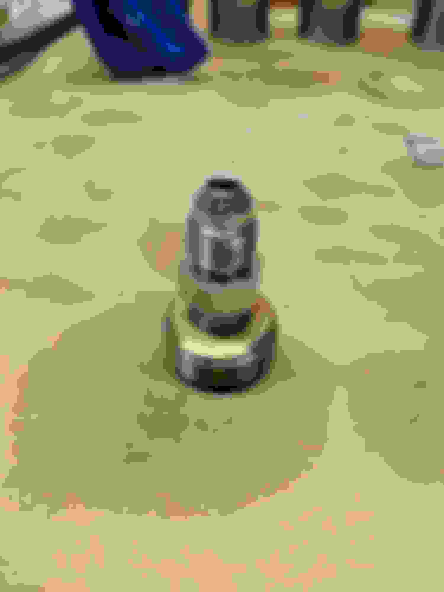
You'll need one of these valvetrain C clamps to disassemble and reassemble the valve gear.
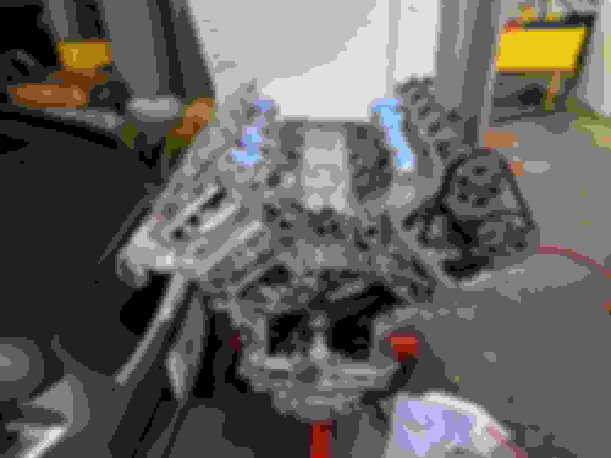
Gear installed
Valves installed
I'm not going to lie - getting the valve keepers back in was not easy. I found the best method was to install the valve, the spring, and the retainer, and compress them so you have a decent amount of space below the valve groove. Then put some engine assembly grease (I used Sta-Lube Extreme Pressure Engine Assembly Lube from O'Reilly Auto Parts) on the inside of the keeper, and then use a magnetic screwdriver to place the keeper into the groove on the valve stem, The grease will hold it in place while you install the other one the other side. Then slowly unwind the C clamp as you guide the retainer over the keepers, making sure you don't catch them and pull them off the valve stem. I found a useful addition was a small non-magnetic screwdriver to adjust the placement of keepers.
Great work Dave, way beyond my level of competence and ability!
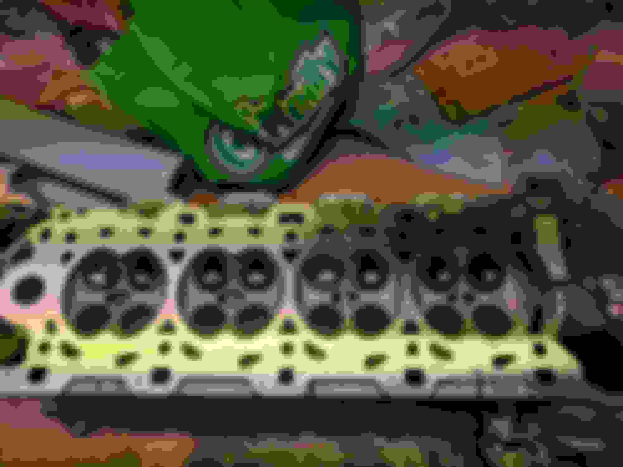
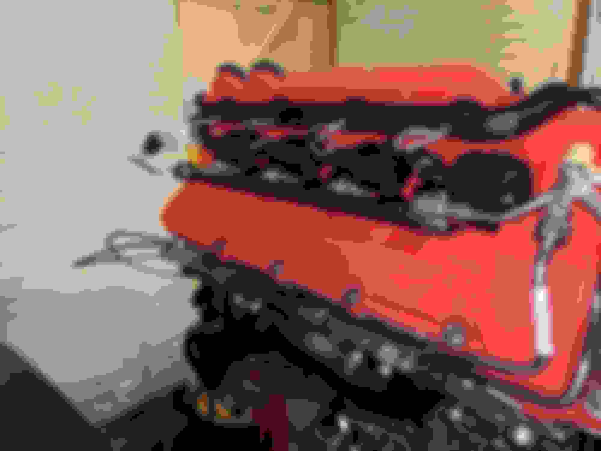
One stooopid question though, what are those holes next to (on the left of) the spark plug holes for?
Edit - I'm a doofus - of course they are the direct (fuel) injection ports!
New auxiliary timing chain, guide, tensioner, and oil pump pulley fitted. The new chain had three colored links on it vs two on the old chain, but the outer two links still line up correctly with the old chain.
Upper sump fitted
Fuel pump followers fitted
Brand new high pressure fuel pumps
New Exhaust manifold gasket fitted
Ceramic-coated exhaust manifold (to try and combat engine bay heat soak) fitted with new bolts. I also cleaned up the metal spacers with a brass wheel on the bench grinder.
Hi Dave ,
great to see this pictures.
I can see that you have already installed the camshafts.
How many graded tapets you had to buy to get the valve gap adjusted
the correct way or did you rework the old ones by grinding the inner side ?
Next step for sure you will install the timing chains.
Im very interested in the procedure of torquing the central screw fixing
the lower chain sprockets to the spec values . 200Nm of
pre-torque and additional 270 degrees of angle as mentioned
in my f-type manuel makes me thinking how the screw will
withstand this load and what amount of torque is necessary
to achieve this values ? Can you give me information about
the thread size , pitch and length of this bolt ?
Very curious about your experience.
How many graded tapets you had to buy to get the valve gap adjusted
the correct way or did you rework the old ones by grinding the inner side ?
So far I've only checked the clearance on one head, but they were all (pretty much) in spec of 0.25mm +/- 0.02mm on the exhaust valves and 0.20mm +/- 0.02mm on the inlets. I'm currently trying to find out if this is expected because not having to adjust any of them seems very convenient, although given the price of graded tappets (about $25 each IIRC) maybe I shouldn't be complaining. I'm assuming grinding the inner side would only be required if the clearance was too low?
Originally Posted by f-driver
Im very interested in the procedure of torquing the central screw fixing
the lower chain sprockets to the spec values . 200Nm of
pre-torque and additional 270 degrees of angle as mentioned
in my f-type manuel makes me thinking how the screw will
withstand this load and what amount of torque is necessary
to achieve this values ?
Yeah, that bolt is in tight. You'll be delighted to know, as with so many things on this engine, that there's a special tool for use with this bolt - this tool bolts to the crankshaft pulley and rests on a jack stand to stop it turning - I've attached the relevant workshop manual section.
I must confess that to get the original bolt out I just used the flywheel locking tool and a high-power impact gun, which worked spectacularly (though I still needed a puller to get the crank pulley off! I can't imagine how hard it would be to get that sucker off with the engine in the car, unless you took the whole front panel off for access.
Originally Posted by f-driver
Can you give me information about
the thread size , pitch and length of this bolt ?
Very curious about your experience.
Sadly the bolt is in the crank at the moment to aid with turning it but if I remember rightly it's an M16 bolt (or at least, you need to use a 16mm washer to protect the crank when just using the bolt to turn it), reverse threaded (on mine, some differ, see below), and 12.9 graded. The standard threaded bolts are 10.9 graded.
12.9 is one of the highest grades of bolts generally available - according to this table, the general torque figure for an M16 12.9 bolt is 250 lb/ft which comes out to around 338 Nm, so obviously the initial tightening of 200 Nm is way under this figure. However, it's impossible to know the additional torque the further 270 degrees of angle would add to this figure, but it's a big, sturdy bolt. Personally, I'd be more concerned about the integrity of the crankshaft the bolt is screwing into, especially considering the amount of material around the bolt. Still, I figure we're just dealing with materials that have strength that's difficult to imagine - forged cranks, etc - and people are paid a decent salary just to calculate all this, so they know more than me
This seems as good a time as any to point out you need to check the numbers printed on the crank bolt before removal as detailed on page 6 of the attached doc. There's a couple of stories on here in different car sections (e.g. XK) of mechanics reporting the bolts have snapped and that's 100% because they didn't follow the workshop manual and therefore weren't aware the bolt they were removing was reverse-threaded.
Take one 1/2" NPT to 1/8" NPT adaptor without a hex head on it (available in this kit), and add a 1/8" NPT to -4AN adaptor...
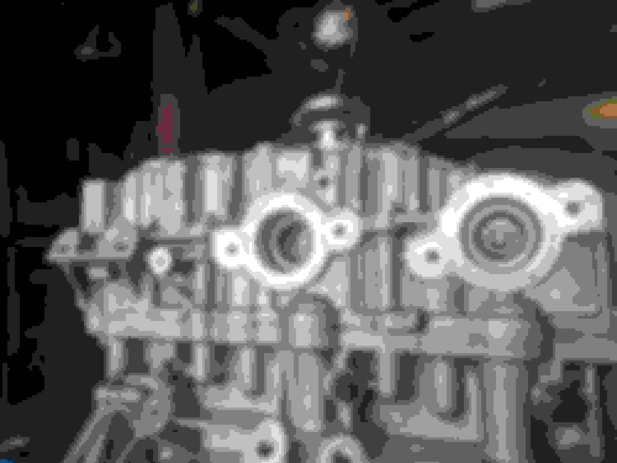
And you can connect a braided hose to the usually-plugged threaded oil feed hole on the side of the block
This hole T's into the supply pipe straight from the high-pressure side of the oil pump, and it's my suspicion that this hole was originally intended for an oil pressure switch (which as we know is not fitted to these engines), maybe nixed because of the proximity to the exhaust manifold?, but it's possible that it's also used for pre-oiling during initial assembly.
I'll certainly be using this for both - to prelube the engine before initial start but also to tap an oil pressure and temperature sensor to once the engine is installed.
I've also started fitting all the 8mm timing gear:
Here's the new style chain tensioner guide showing hardened metal on the back
8mm chain timing marks line up nicely with all 8mm gear installed
All new 8mm VVTs to go with the chains
Sloooooowwwwwly starting to look like an engine again
>YOU are amazing Dave
Wow, just wow, big thanks for sharing all of this with us.
================================================== ===========
Understeer is when you hit the wall with the front of the car
Oversteer is when you hit the wall with the rear of the car
Horsepower is how fast you hit the wall, and
Torque is how far you take the wall with you
Dave, are you going to have it dynoed out of the car? All those tight clearances and small orifices make me glad I do frequent synthetic oil changes. Great job my friend, you make in down to the LA area, I owe you a cold one for sure! Love the license plate too..lol
Dave, are you going to have it dynoed out of the car?
Good question - to be honest - probably not. That's going to take extra time (and money) that I'm not sure I can justify. I'm having to move house in 6 weeks and the car is currently immobile so the priority is getting the engine built and then getting the car towed to the shop I was working on and drop the engine and transmission back in.
Originally Posted by Bigg Will
Great job my friend, you make in down to the LA area, I owe you a cold one for sure!
Well once it's built it's going to need running in - sounds like a good excuse for a gentle run down to LA to get the miles on the clock!
Timing gear fitted and set. Covers sealed and bolted.
A few things of note here:
All the 8mm gear fits without issue and does not require new timing covers, despite there being a differentiation on parts sites between the 6.5 and 8mm timing chains for the covers. I've successfully fitted all 8mm gear into my originally 6.5mm setup.
The Jaguar service manual is specific about a step I've seen other guides miss: after pulling the pin out of the tensioner to release the tension, you need to push on the tensioner blade enough for the tensioner to hit the ratchet stop - if you can push the tensioner back in, you haven't got it yet.
When pushing on the tensioner blades in order to allow the tensioners to hit their ratchet stop, the service manual states to use considerable force - they are not ****ing around here. In the end I had to lever it hard with a socket extension bar in order to get it to ratchet. The "click" isn't as audible as the service manual implies, but you'll know when it's done as you won't be able to push the tensioner blade back.
There are also steps the service manual gets wrong, for example, fitting the oil vacuum pipe: the manual says to do this after you've fitted and set all the timing gear. However, there's no possible way of doing this after the timing gear is fitted, as the pipe goes behind the chains, as is one of the fixing screws:
The way I found worked was to install the vacuum pipe before any other timing gear, but only tighten the lower screw (to 12Nm). This is the screw that gets covered by the timing chains. Then you'll have enough flex at the top of the pipe to move it out the way enough to install the VVT tensioning C clamp (which I suspect is why Jaguar said to fit the pipe afterwards, but as you can see above it's physically impossible.
Special tool 303-1433, used to center the lower timing cover on the crankshaft, is not needed, unless you're super clumsy. No idea why the manual thinks otherwise, but I have one of these tools now if anyone needs one.
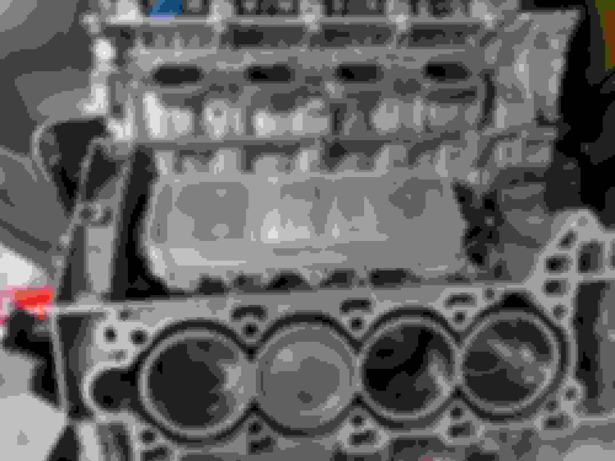
The build is looking great Dave! I noticed the FoMoCo stamped on the head, I wonder how many internal parts that engine shares with the Ford 5.0? Did you investigate that?
We have gone over this dozens if not hundreds of times.
One more time;
The Ford 5.0L V-8 and the Jaguar 5.0L V-8 do not share ANYTHING!!!
Yes Ford did own Jaguar and massively improved the build quality and manufacturing capabilities of Jaguar. The numbers are quite stark-Ford put billions into Jaguar and apparently never made a dime of profit on the entire transaction.
In fact as you noted they still make a number of parts from that union that ended back in 2008 or so. These Ford made parts are slowly fading away as that relationship continues to die out.
Example; My 2014 XJR water pump has no brand cast into it. Yet on this list we have pictures of the exact same pump with JLR and Fomoco cast into the body.
The only thing the two engines share is the 5.0L capacity!
.
.
.
OK OK OK!!!! lol. I just never expected to see that stamp on the casting.
>And... that�s why they never made a profit with Jaguar...
Or with Volvo, or Aston Martin, or any of their "prestige" brands.
And then the financial collapse of 2007-08 happened.
Do you know why Ford is still in business (unlike the old GM or Chrysler)?
It's because instead of declaring bankruptcy (and either taking government hand-outs or being acquired by Fiat) they sold all there non-core car lines along with all their property. Right FMC now rents all the factories and office buildings. etc.
================================================== =
You dreamed of a big star -
He played a mean guitar -
He loved to drive his Jaguar...
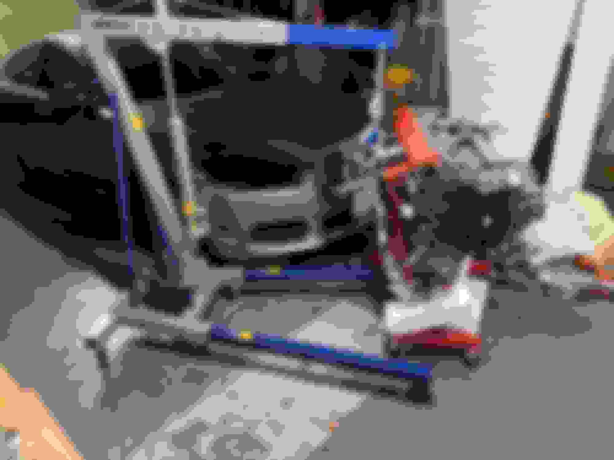
Another update with a lesson: Don't forget the rating of your engine stand when trying to undo stuck coolant drain plugs. Yes, I should've done this before I'd built the engine up but honestly i'd forgotten about it for a while. I have an AC-powered torque gun but it's not particularly powerful, so I tried with a breaker bar. On a cheap, 1000lb engine stand, this went about as well as you'd expect:
BAD.
VERY BAD.
Sadly due to the weight, this necessitated the purchase of an engine crane and leveler to rescue the engine in it's current predicament:
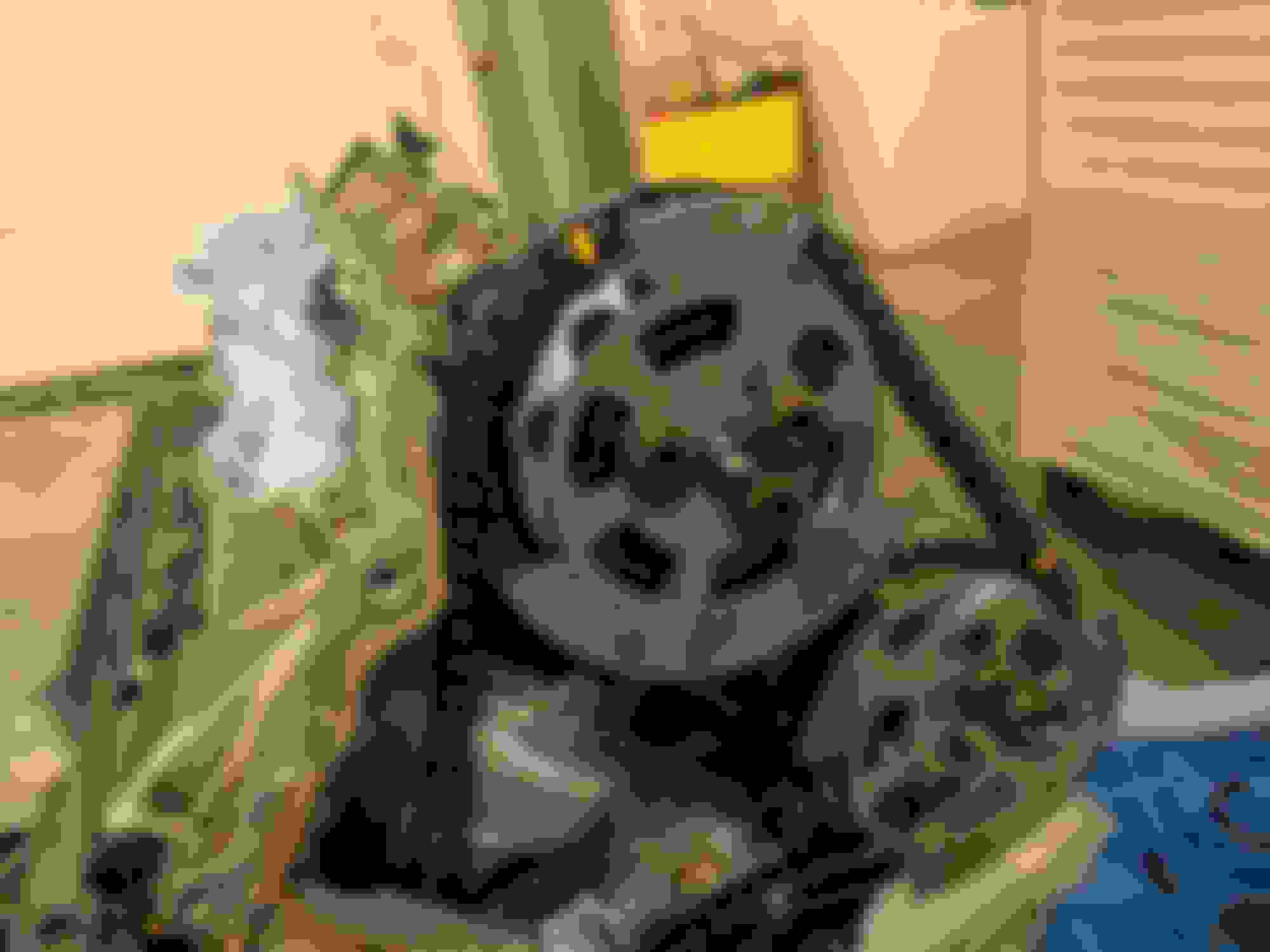
Once off the broken stand, I was at least able to fit the rear crank seal:
This requires a special seal-splaying tool that bolts onto the crankshaft
New crank seal fitted
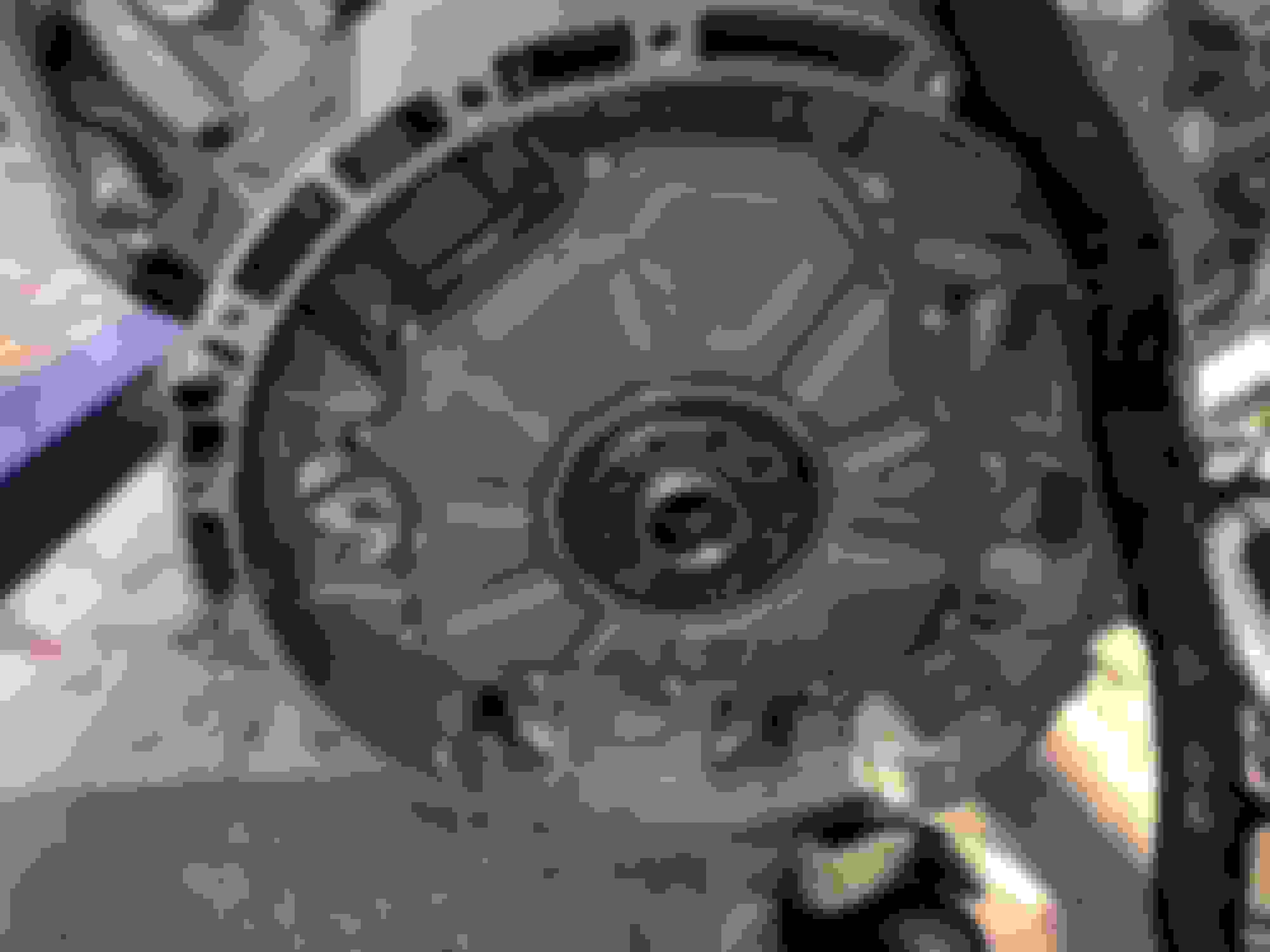
Flywheel/Flexplate/whatever you want to call it fitted.
The flywheel bolts are torque-to-yield, so I figured it was worth fitting new ones. Top tip: I also marked each bolt with a sharpie once I'd angle-torqued it so I could keep track and didn't accidentally double-torque one twice or something and end up shearing the bolt off in the crank - doesn't bear thinking about at this point. Another way to do this would be to use a digital torque wrench to measure the torque required to turn the bolt the required angle, so you know if a bolt has been already angle-torqued or not.
Then I could get the engine back onto a (higher-rated) stand
Sorry did not mean to get on you! A little sensitive for a Jaguar guy I guess.
Yep it cost Ford dearly to dabble with those high end car brands. But it's not the first time.
They sold almost everything and then had to compete with GM who got the government handout.
Remember the whole winning Le mans effort was because Henry Ford got turned down at the last minute by Enzo when he was trying to buy Ferrari
And sorry for derailing a very interesting thread.
.
.
.
Last edited by clubairth1; 06-02-2018 at 10:31 AM.
 04-30-2018, 01:45 AM