When you click on links to various merchants on this site and make a purchase, this can result in this site earning a commission. Affiliate programs and affiliations include, but are not limited to, the eBay Partner Network.
I have rebuilt four of these engines. Three are running fine (touch wood), one has 12K on it. All have been timed the same way. On this one engine (in a Range Rover but who cares) I get P0017 error code, exhaust crank/cam correlation error. When I look at the timing it is jumping between 120deg and 150deg on bank 1 at idle. It shouldn't be able to adjust above 120deg as it should only be able to retard from static. The other bank shows steady around 120deg. If I remove the solenoid and press the center of the cam sprocket with a screwdriver the timing dives down and the engine runs rough, as one would expect. Still flickers up to 150deg though.. Release and it comes back. I cannot think how this can be a mechanical problem so wonder if the cam signal is getting electrical interference or something. I have changed the cam sensor. Looked at the signal on a scope and it looks clean enough. Notice how square the top is at 150. Can anybody shed any light on what may be occurring?
Here are two graphs showing both banks exhaust cams timing over 10 seconds period. The first is the bad one, the second is the good.
I ruled out mechanical issues because when I press on the center of the sprocket when the engine is running (using a screwdriver handle instead of the solenoid) the timing dives to around 70 degrees. The exhaust sprocket can retard up to 50 degrees and 120-50=70. It should not be able to advance to 150, it would have to turn the opposite direction from the lock point. That is how I understand it anyway and I have taken one apart to confirm. Usually when they break internally they rattle and I did find one before assembly that was broken. And the squareness at the 150 mark on the graph suggests to me something is maxing out, maybe software limits? I think I might try another ECU.
Broken sprocket (inlet), lockpin lobe is very week which is probably what breaks if they are dropped......I know you had a faulty one, did you every dismantle it? What kind of timing errors were you seeing when the engine was running?
Last edited by kansanbrit; 06-24-2021 at 08:10 AM.
your first diagram shows engine speed of 694 rpm hence camshaft signal should
occur approximatly every 0.173 seconds. So your ECU calculates a new angular
value approx. 6 times per second which can obviously be seen in your diagram by
the red signal of bank 2. Because the angular value is calculated from engine speed
(angle = speed * time) and the timeperiode between crankshaft signal (TDC) and camshaft signal
any delay or missing of the camshaft signal will lead to a greater angular value
which explains flat spots as well as values greater than 120 deg.
Perhaps distance between sensor and trigger disc on bank1 exhaust cam is out of spec
or it`s "simply" an electronic problem.
Try to check the time interval of the cam sensor signal with your scope to narrow down the problem.
Great thoughts f-driver (I'm one too :-) but I am pretty sure the cam signal is good. Here are scope images, signal looks rock solid. I have another ECU on order, I think it might be missing pulses internally. Thanks for your input.
Also, I did wire up the solenoid with a battery so I could document what happens when it is actuated, sprocket altered timing as expected. By the way, ignore RPM values on graph for some reason reading freezes in graph mode on GAP device.
When I drive the car harder I get this kind of occurrence below...... Puzzling.
I think I will check the cam signal at the ECU connecter next just to confirm that I don't have an intermittent wire.
Last edited by kansanbrit; 06-26-2021 at 04:37 AM.
I know you had a faulty one, did you every dismantle it? What kind of timing errors were you seeing when the engine was running?
Honestly, I completely forgot to ever dismantle it. I'm sure I've still got it so I'll try and dig it out. Here are the codes I was seeing:
P0017-00: Crankshaft position - camshaft position correlation - bank 1, sensor 2
And if it's any help, my Autel scanner listed the following as the reference for the code:
Possible Causes:
Note: Repair guidance documents references - VFS_EX_A
The relative positions of the crankshaft position sensor and camshaft timing plate teeth are not correct
Engine timing incorrect
Timing chain installed incorrectly
Variable valve timing forcibly advanced
Actions Required:
Check for related DTC code P0365-00
Check engine timing
Check camshaft sensor timing plate is installed correctly
Check timing chain is installed correctly
Check exhaust (B) camshaft position actuator (Bank 1) for open circuit, short to ground, short to power
I mention this because none of that included the possibility of a broken phaser, which is what my problem turned out to be. I did much the same diagnostics as you with scoping signals and comparing them to what the Autel was logging, and you could see the exhaust cam was "struggling to maintain" the angle the ECU requested of it, at which point it threw the above code and went into restricted performance.
Originally Posted by kansanbrit
I think I will check the cam signal at the ECU connecter next just to confirm that I don't have an intermittent wire.
Concur, that was going to be my next suggestion. How many channels on the scope? Might be worth seeing if you can get the crank signal at the same time to see if you can spot anything the ECU might not be happy with timing wise.
Also, when does the ECU throw the code? Immediately on startup? For reference, mine would only do it after a second or two when I put the engine under load (even creeping in drive) - if I just started and idled it wouldn't, so it was only at the point the ECU wanted to modify the timing that the code was thrown, which I guess helped me narrow it down to the phaser.
It would be nice to see the insides of your faulty unit if you get a chance.
The cam signal is fine at the ECU pin. I only have a single channel scope at the mo but I could get a hold of a dual channel. The problem is I would really need the one trace to trigger on the extra wide pulse from the crank transducer (as opposed to the other 60 or however many there are) so that I could see if the cam signal is fluctuating relative to it - and I am not sure I could do that without a logic analyser or something.
The code comes up immediately most of the time. Funnily enough, if I clear it and it doesn't trigger on startup it will never come up until another restart. I mean I could drive all day and it won't come on I'm sure but I can always see it fluctuating on the scanner. Do you know under what conditions the exhaust timing should start to change? Its a bit of a bugger !!
Last edited by kansanbrit; 06-27-2021 at 02:54 PM.
your problem caused me to go deeper into the cam actuation mechanics of this engine. Out of several documents I gathered over the years I could extract data to create
a timing chart which might help to get a better idea of what is going on.
Timing actuators :
Both actuators (exhaust and inlet) have the same intial position as shown in the picture. This position is fixed by the locking pin of the actuator.
If the locking pin is released the bias spring will move the actuator to opposite end position. Initial position must be maintained during the engine
timing process. Naming convention according to the workshop manual of the position is "fully retard" for the intake side an "fully advanced" for the exhaust side.
Timing chart :
valve lift curves aren't correct, only for illustration of the cam timing position. solid line represent the initial position where as dashed lines show the fully actuated position.
So all information is based on written information only, so any correction from experienced master mechanics would be appreciated.
@kansanbrit
Assuming crankshaft zero position is compensated by software to 0� for TDC of left and right bank, exhaust cam should act in between appr. 120� to 170� ATDC .
As bank 2 moves from 110� to 130� driving harder I think reference position (0� TDC) might be correct.
So according to your chart bank 1 cam moves back and forth between both limits being out of "hydraulic control" which seems to be a mechanical (hydraulic) issue.
No idea why you can go to 70� (from which reference wherever) when using a screwdriver handle instead of the solenoid. Does the "good side" behave identical
performing the manual test ? Hopefully the new ECU will sort out the problem.
Thanks for the effort you are putting into this f-driver and sorry about the soccer result :-)
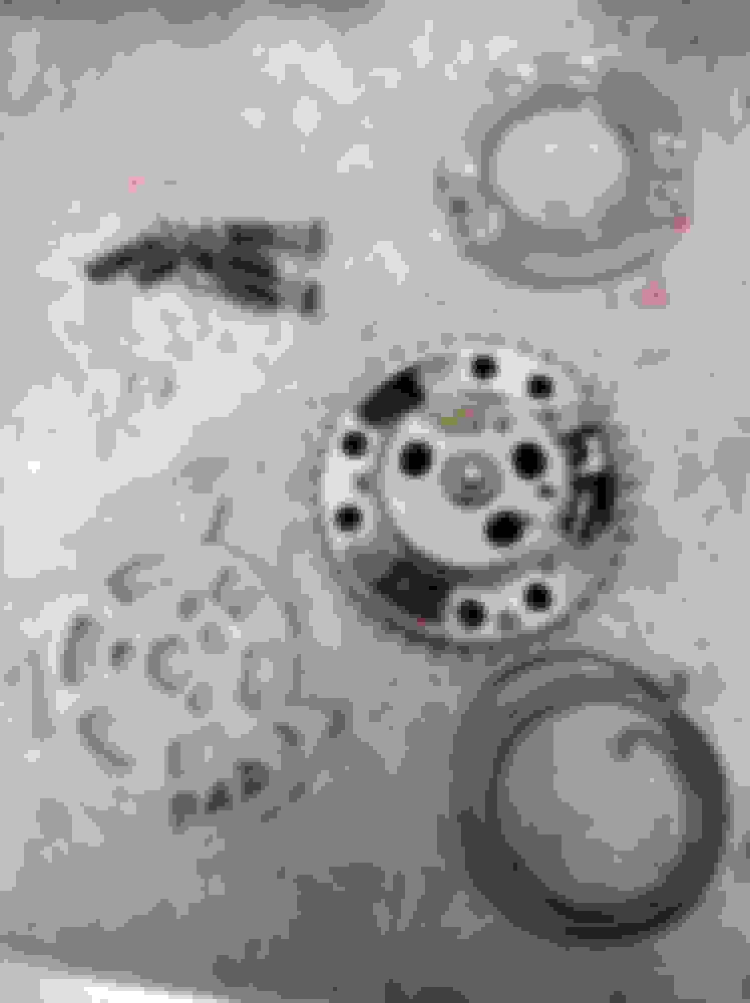
Here is a photograph of sprockets showing intake (broken) version on the left and exhaust on the right. As far as I can tell the only obvious difference is the the locking mechanisms are in different positions. Intake top of chamber, exhaust bottom. The springs pull both in the same direction (surprisingly).
Your picture showing the two sprockets shows them as being identical so I don't see how can one be advanced and one retarded? Surely they can both only move the same way if that were true? Or am I missing something obvious?
If the springs move them both the same way when the engine stops how does one of them get to the lock position? Missing something here I guess.
This is an extract from the AJ133 systems manual:
"The VCT solenoid force is controlled with a pulse width modulated (PWM) duty cycle at battery voltage. When the VCT solenoid is not energized, the phaser pintle is fully extracted (via spring force), locking the camshaft in the base timing position.
The intake camshafts will be in full retard and the exhaust camshafts will be in full advance. Under operation, the intake camshafts can advance 62� crankshaft angle; the exhaust camshafts can retard 50� crankshaft angle.
To hold the camshafts in any other position other than the base timing lock position, the ECM partially energizes the solenoids – holding them in the ‘null’ position.
To retard the intake camshafts, the opposite is true, where the VCT solenoid is powered with a lower duty cycle and then returns to the null position once the target angle is reached.
The exhaust camshafts operate in the opposite manner to the intake camshafts, where the solenoid is energized to retard the exhaust camshafts and underpowered to advance the camshafts."
This suggests the springs is needed to return it to the lock position so I would expect springs operating in opposite directions. Puzzling.
One thing to note is when I actuate the solenoid and the reading goes down to 70 degrees, the graph still has peaks of 150 degrees. That is an 80 degree change and I do not think the mechanics of the sprocket will allow an 80 degree change, it should only allow a total of 50 for the exhaust at least. And if the mechanics did allow that and it is broken why would it not swing wildly between the two limits.
Here is what the system is supposed to do I believe....exhaust retard, intake advance. Your picture shows both cams moving the same way. I think my angle gets smaller when I actuate the solenoid because it is BBDC figure or something.
ECU coming this week. Thanks again.
Last edited by kansanbrit; 06-29-2021 at 05:15 PM.
due to the priceless information given by the pictures of the disassembled VVT units from kansanbrit I would like to correct some faulty information of my previous
post, just for the reason not to spread misinformation.
Timing actuators :
Exhaust and inlet actuators have different intial positions as shown in the picture. This position is fixed by the locking pin of the actuator.
The bias spring on both actuators applies a torque to the camshaft in a way that moves the camshaft in direction of rotation. So releasing
the locking pin on the exhaust VVT will cause no movement whereas on the intake VVT it will move to fully advanced positon.
Initial position must be maintained during the engine timing process.
Timing chart :
valve lift curves aren't correct only for illustration of the cam timing position. solid line represent the initial position where as dashed lines show the fully
actuated position.
@kansanbrit
bias spring acts in the same direction on both VVT's to compensate for the friction of the camshaft bearings. The idea behind it is to have equal pressure levels in
the retard and advance chambers during VVT null operation. Furthermore retard and advance movements can be done by the same pressure difference.
Locking position is achieved by the design of the spool valve of the VVT not by the bias spring. When you push the pin of the spool valve it starts releasing the locking pin.
Pushing the pin a bit more oil is distribute in a way that the intial position is maintained. Pushing the pin fully in will cause the VVT to move in the opposite direction.
Because the pin is pushed back to the start position by a spring each loos of electric power, intentionally or by mistake, the spool valve actuates the VVT in the lock position
by itself. Somewhere I read that this will occure in about 0.3 seconds.
So releasing
the locking pin on the exhaust VVT will cause no movement whereas on the intake VVT it will move to fully advanced positon.
Initial position must be maintained during the engine timing process.
@F-driver just one comment after thinking about this again; I think when the intake unlocks it will stay where it is as it will be locked fully retarded and only advance when required just as the exhaust retards. Does that make sense?
Last edited by kansanbrit; 07-01-2021 at 05:09 PM.
So, new ECU received, programmed and updated. Guess what, graph still looks the same. However the P0017 error has not been triggered yet after several starts and drives. Fingers crossed. Maybe the data out signal on all this model ECU is screwed up. Time will tell.
@F-driver just one comment after thinking about this again; I think when the intake unlocks it will stay where it is as it will be locked fully retarded and only advance when required just as the exhaust retards. Does that make sense?
when the locking pin is released by the spool valve both actuators keep their initial condition unless the spool valve is commanded by the ECU to change the initial timing condition.
Great news that the error is gone.
Sorry to reanimate thisnthread but you gentlemen are speaking the language I need to hear...yet I am not very versed in the knowledge.
on the 5.0 S/C, I have tossed around the idea of having stock cams reground. Some things I do not know is piston to valve clearance, lobe separation angles, and other specifics. I also see you speaking of the ecm searching for certain angles.
Any chance you could educate me on if it can be done and why not why not? Thanks for any help.
I think the only way you are going to get that kind of info is by taking an engine apart and sticking the cams on a tester and doing clearance measurements. I will be taking one apart fairly soon as I have one with a failed head gasket so maybe able to help then.
 06-23-2021, 11:01 AM