When you click on links to various merchants on this site and make a purchase, this can result in this site earning a commission. Affiliate programs and affiliations include, but are not limited to, the eBay Partner Network.
Hi All
Having read all the stories of replacing the rear wheel bearings I put together some instructions that are hopefully helpful. JLR wheel bearings are often a beast to work on, and even some professionals give up on them. However with the right tools it�s a fairly easy job.
Basically no JLR special tools are required, the key is a very strong hub puller and / or a work shop press rated at least 20t, plus Seeger ring pliers for 85mm diameter snap rings.
Keep in mind that the wheel knuckle is made from aluminum and is easily damaged on the workshop press if not properly supported.
To avoid surprises I suggest to measure at the beginning on how deep the half shaft is inside the wheel hub. That will enable to tell you at the end if the half shaft was properly installed. Typically its 6.2 - 6.3mm inside the hub.
To begin, remove rotor and brake assembly. No need to disassemble the brake assembly, just loosen the brake support�s two bolts and slide the whole assembly off the disk. Secure the caliper with zip ties to the lower control arm so it�s not hanging on the brake hose.
Remove the abs sensor and tuck it away so it does not get in the way.
For the actual bearing replacement there are two approaches:
Pull the hub and then remove the wheel knuckle. That�s the procedure laid out on the JLR workshop manual. Unsuccessful attempts may leave the wheel bearing intact, so you can still drive to the next shop if needed. Downside is you really need a very, very strong hub puller. DIY 10t or 15t puller will likely fail, even with a lot of heat applied. Using stronger puller bears the risk of damaging the hub. Some people managed to get the hub off using sledge hammers, but I�m always hesitant to use hammering tools on delicate parts like the half shaft�s CV joints.
Second approach is to remove the entire wheel knuckle together with the half shaft. The knuckle itself will come off without any special tools, just remove all bolts and lift up the upper control arm. The half shaft removal itself might be a bit tricky as it is hold by a stubborn securing ring inside the differential. Use a crow bar between diff housing and CV housing to pull the half shaft out of the differential. I prefer that method over hammering on the CV housing because you have much better control on the forces applied. Do not pull on the half shaft�s end, you risk to pull the CV apart. Once the half shaft is released, be extremely careful with the differential seal whilst pulling out the half shaft. Ideally you are under the car and hold the half shaft with both hands to make sure it slides out as straight as possible.
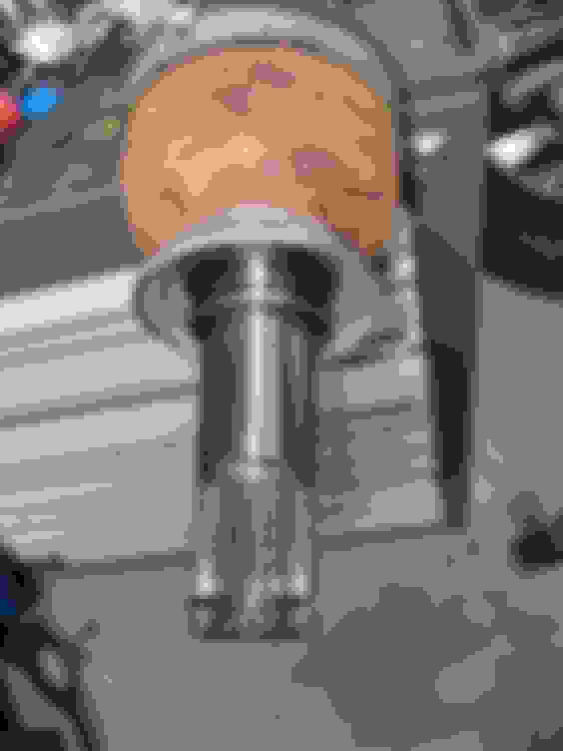
Half shaft with the securing ring. You can see some crow bar marks on the CV joint housing.
Once the knuckle is out, with the half shaft still in place the first step is to press out the half shaft. It typically requires 20-25t on a workshop press. Carefully put supporting pieces under the knuckle to make sure it is absolutely perpendicular to the press. After this step there is no way back as this will destroy the bearing. The half shaft will probably come out with a loud bang, so it is a good idea to either put on the axle nut loosely before pressing out, or make sure the half shaft cannot fall down once it breaks loose.
After that the hub needs to come out. I usually use a copper piece with two diameters, one to slide inside the hub, the bigger to sit on the hubs outer diameter, and then hit it a few times with a heavy hammer. You could also use nuts from ratchet kits, but be careful not to damage the hub.
From here on the procedure is similar for both approaches. Likely the wheel bearings inner ring is stuck to the hub, with very little room to grab it. It�s not sitting very tight though, you can either heat it up with ace/oxy and it will just fall off the hub. You can weld something to it and pull it off this way. The heat of the welding will likely loose it enough to take it off easily. The third approach is to use a bearing separator.
Next piece of resistance is usually the snap ring that holds the bearing in place. The snap ring is usually rusted in place. Use a pin punch and tap around the snap ring to break it loose from the knuckle's aluminum housing, then it should come out using the correct size Seeger ring pliers. With the snap ring off you now can press out the bearing. Again, a lot of force will be required, so make sure the knuckle is supported on the full diameter to avoid damages. Pressing out will be 15-20t.
With everything disassembled, it�s time to clean all parts and remove rust, especially from the half shaft and hub mating parts. These two parts must slide into each other easily.
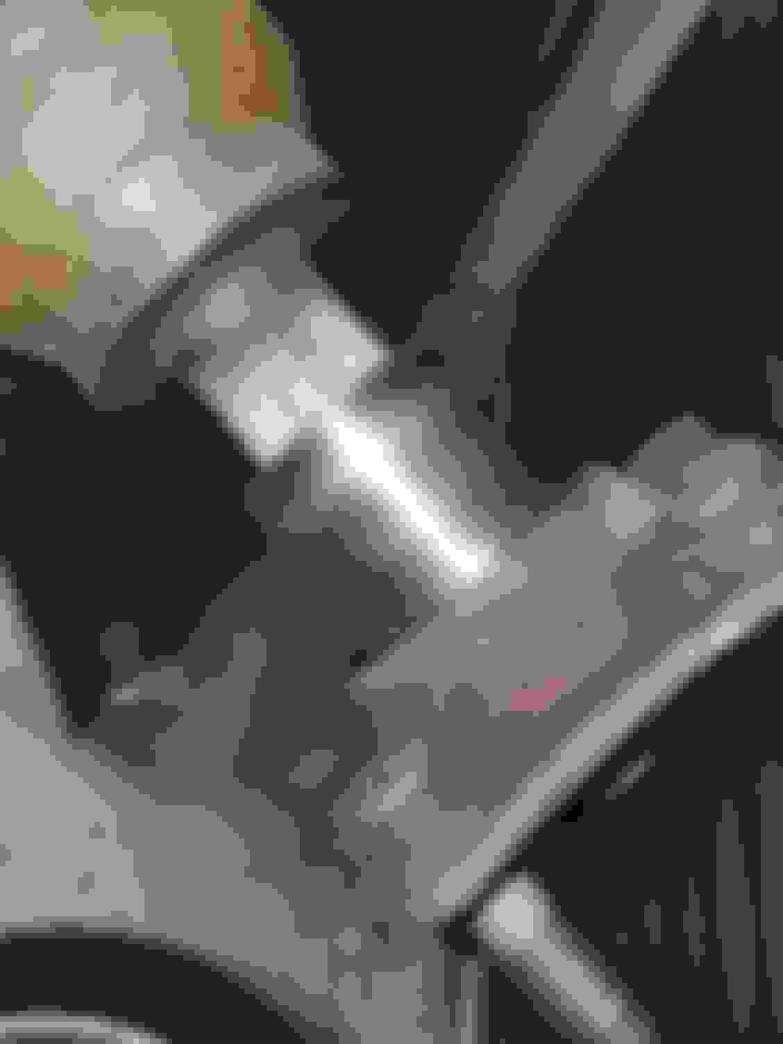
Testing if half shaft and hub slide in easily
To reinstall the new bearing, you can use the housing of the old bearing to press it in. Make sure to put force only on the outer ring whilst pressing the bearing inside the knuckle. A good practice is to send wife away for shopping and use the kitchen oven to heat the knuckle up to 200�C. The new bearing will then just fall inside. Make sure the magnetic ring goes inboard, as otherwise the abs sensor will fail to work.
Do not forget to add the new snap ring before pushing the hub back in place. Pushing the hub in will require 5-6t. Pressure must to go only on the new bearings inner rings. To do that you can use the old bearing�s inner ring plus the old bearing itself to create a stable support from the inboard side.
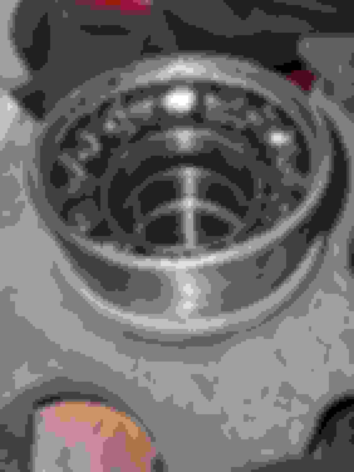
Old bearing housing and inner ring used to support new bearing
If the half shaft was removed, reinstall it now to the car. Be extremely careful with the sealing in the diff housing. Ideally do this from under the cars so you see what you are doing. Just pushing in from the side will likely damage the seal.
Now put the knuckle back on the car, secure the upper control arm first and slide the half shaft thru the hub. Put in the other bolts that secure the knuckle, but do not tighten them yet. Use the axle nut to pull the half shaft in place, but do not fully tighten it. It�s a good idea to check now if the half shaft is properly installed using the measuring from the beginning of the procedure.
Put back the brake assembly (103Nm for the bolts) and do not forget to reinstall the ABS sensor. Place the car on the wheels and secure the knuckle bolts. 90Nm for the upper arm, 55Nm for the control arm on the side and 150Nm for the lower control arm. Tighten the axle nut with 300Nm
Great how-to. I just had my rear wheelbearing and a rear upper suspension arm replaced by a local (to Glasgow, Scotland) mechanic. He was at it for many hours over two days (the car recently clocked up 250,000 miles and is showing its age) and charged me 175GBP labour, He's a keeper! Parts; I think I paid about 30GBP(Bearing), 100GBP(suspension arm). He had a selection of large, heavy pullers and slide hammers, this was not an easy job on my car.

 09-15-2021, 04:55 AM