When you click on links to various merchants on this site and make a purchase, this can result in this site earning a commission. Affiliate programs and affiliations include, but are not limited to, the eBay Partner Network.
2016 -2019 XJ InControl Touch Pro 8” to 10.2” factory upgrade
This is a 5 part thread to break the content up into more manageable sections. It is quite picture-heavy, so I apologise if it is slow loading but I wanted to be sure every step was covered in enough detail that you could reproduce it if you want to.
Part 1 - Introduction
If you have the InControl Touch Pro 8” infotainment system this thread will show you how you can replace it with the 10.2” factory system fitted as standard equipment to the 2019MY.
To be very clear – this upgrade is only possible if you have an existing InControl Touch Pro 8” system. These are sometimes referred to as NGI (next generation infotainment), and use the IMC (infotainment master controller) located in the boot/trunk behind the left hand carpet trim. This system was fitted to the XJ from the 2016MY, which is typically from VIN V90866 (although some cars as far back as V88000ish were built as 2016MY).
A similar process may be possible with other ICTP/NGI vehicles in the JLR range, but I have not attempted them.
The IMC does not need to be replaced as the software can simply be configured to use any combination of 8”/10.2” and single view/dual view. There are no wiring changes. If you have the 360 camera feature (front and side cameras) then you will need to replace the IPMB module behind the back seats if you want factory functionality (but it will still work with caveats). If you just have the reverse camera you don’t need to replace the IPMB.
Because the IMC is not replaced there is no effect on your InControl Pro services, and map updates, etc, are unchanged.
This upgrade requires a fair amount of disassembly of your dashboard/instrument panel in order to replace the central reinforcement bracket, so is a 9/10 on the difficulty scale, and will take about 8 hours.
I will detail each step further, but in summary:
New parts needed:
10.2” factory screen. I have tested with various single view and dual view screens fitted to both Jaguar and Land Rover vehicles and they have all worked so far.
FCIM switch pack (this is the one under the screen with the AC controls, etc). (You can’t retain your current one as the mounting method is different.)
Screen bezel
Instrument panel/fascia central reinforcement bracket.
If you have the 360 camera feature you will need to replace the IPMB camera module if you want the full factory UI, otherwise you will retain the 8” UI from before.
The parking aid button and tell tale lamp in the roof console become obsolete and are replaced by a soft button on the touch screen. You can just ignore the roof button, or replace the roof console for a factory finish.
You will need coded access to SDD to make changes to the CCF for the vehicle and run some module configuration processes.
The process is:
Remove existing screen and temporarily connect new screen so you can test everything before disassembly.
Change the CCF, relearn the vehicle configuration to the IMC module, make sure the PAM (park assist module) is running the latest software.
Disassemble the dashboard/instrument panel and floor console.
Replace the centre reinforcement bracket.
Reassemble everything.
There are some differences from a factory install:
The new facia trim that surrounds the screen and AC controls has a very slightly different outside profile which leaves a 1mm gap along the top between trim and leather (the gap is horizontal not vertical so it is only visible from above and not from the seated position).
Jaguar changed the upper dashboard/instrument panel and floor console upper/side trims with the 2019MY. You will need to cut off 4 brackets to fit the new centre reinforcement.
SOTA updates will only be offered to you based on the as-built infotainment. This means you cannot currently upgrade past version 19A. Any future upgrades will automatically configure for the 10.2” system. (There are ways to flash newer NGI software onto the IMC using SDD and modified xml/vbf files but that is outside the scope of this thread.)
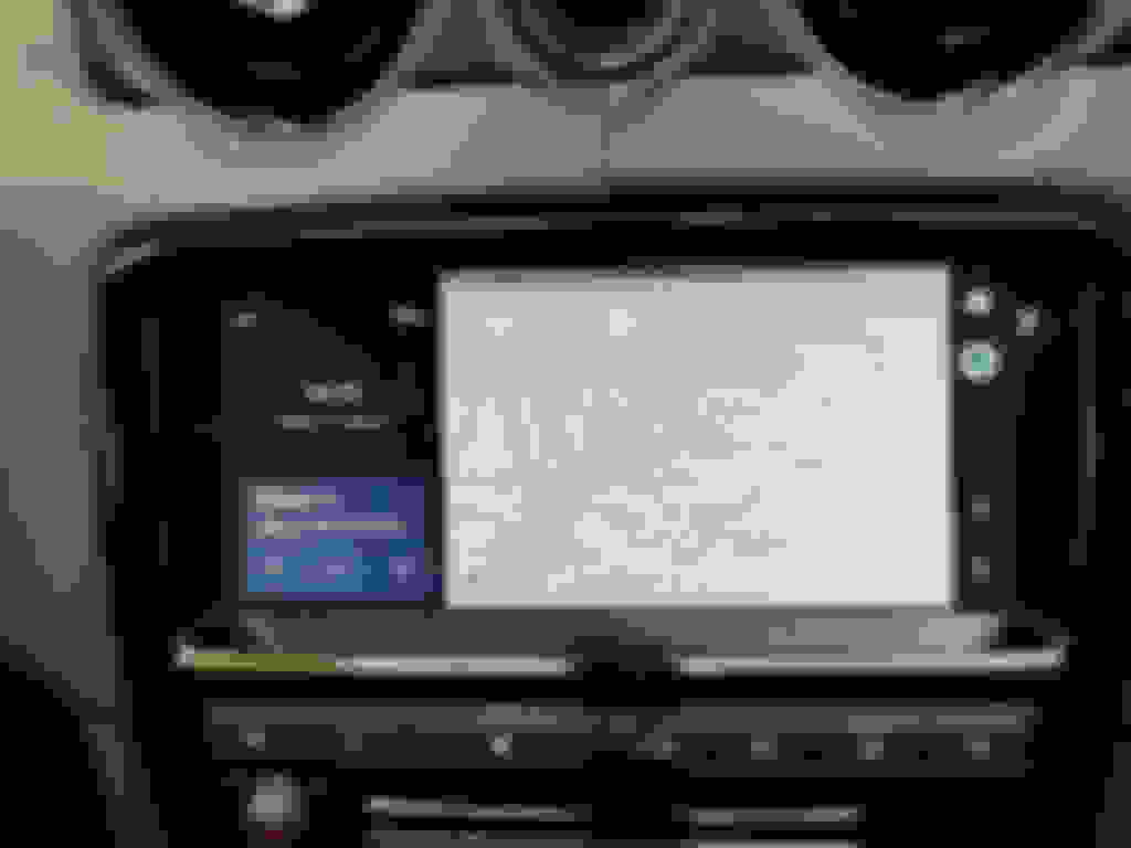
Below are some photos showing the new screen fitted to my 2016 XJR. Excuse the dust – nothing like flash photography to make a clean car look dirty!
I am running software version 19A which at the time of posting this is the latest official version for the 2016 MY cars. 2016.5MY and later may be able to get a later version via SOTA. If you can upgrade to a different version please can you post it this thread along with your car’s model year? You can get the model year from https://topix.landrover.jlrext.com/.
Overall I like the 10.2” system, and having the extra space for map and music browsing is very useful. I don’t use Android Auto or Apple CarPlay, but they are now both available (not supported on the 8” system for the 2016MY). The only thing I dislike is that they painted the inside of the screen surround trim gloss black instead of a matt black as with the 8” versions. That means it reflects the screen at night, as seen in my photos. This was done purely for cost cutting – the old bezels were a three-part assembly with manual heat staking of the matt and chrome trims. The new ones are a single moulded and painted part.
The 10.2” screens are readily available used from eBay and breakers as they are fitted to almost all JLR vehicles since 2016 either as standard or optional equipment. You can easily identify them by two unique features:
They only have a single pink roundish connector on the rear
The label states “FRONT 10” DISPLAY” and in big letters will have either 10SV (single view) or 10DV (dual view) printed on them.
Some example photos are below.
The screen fitted to my car used for the photos throughout this thread is GX63-19C299-BC (dual view). I have also tested with GJ32-19C299-AB (dual view) and GX63-19C299-AC (single view). All worked flawlessly. I paid about Ł150 for each.
If you really want to buy new then the XJ part is C2D53785 for dual view and C2D56665 for single view but they are not cheap!
Black screen/AC panel surround is C2D55049.
Fascia centre reinforcement bracket is C2D53485.
The metal bracket for the screen is C2D54236.
The FCIM/AC control panel you need depends on the vehicle spec:
With start-stop, dual view, heated windscreen is C2D54084 (WERS JW93-18C858-AA).
With start-stop, dual view, without heated windscreen is C2D54088.
With start-stop, single view, heated windscreen is C2D54085.
With start-stop, single view, without heated windscreen is C2D54089.
Without start-stop, dual view, heated windscreen is C2D54086.
Without start-stop, dual view, without heated windscreen is C2D54090.
Without start-stop, single view, heated windscreen is C2D54087.
Without start-stop, single view, without heated windscreen is C2D54091.
The roof console (only needed if you want to remove the parking aid/sensor button which will stop working) part number again depends on the vehicle spec (trim colour, sos/non-sos, etc). There are too many variations to list here. If you can’t find the part you need PM me.
The IPMB (image processing module B, aka the parking camera module) is C2D55068. This is only needed to recreate the factory UI for the cameras as your existing module will still think it is an 8” screen. The IPMB is unique in that it provides its full UI rather than the IMC software. This is likely done so the cameras will still work even when the IMC is loading (start the car and put it straight into reverse and the camera appears even though the IMC is still booting up). If you don’t replace this and have the 360/surround camera system fitted then you won’t get the UI icons on the side of the display for changing the camera view. As the resolution of the 10.2” screens is slightly smaller vertically the icons along the bottom are not shown or selectable so you cannot access them.
Note you don’t have to replace the IPMB if you don’t mind not being able to control which camera/s is being shown. The soft camera button on the display will not function, but the hard button below the screen still works as before. It will also still default to the most appropriate camera view (you just won’t be able to change it):
When in R the rear camera is shown, and if the PDC is active you will still see the coloured bars and positional lines if you have them configured.
When in D and travelling above 15mph you will see the front camera and can select the rear camera by pressing the camera hard button again.
When in D and travelling below 15mph (including stationary) you will see the rear camera and can select the junction view (split side cameras) by pressing the camera hard button again.
When in P or N you will see the 360/top down view first, and can select rear and junction view using the hard button.
Note that the main/upper dashboard/instrument panel and the upper leather trims on the floor console are different with the 10.2” screen. The differences are where they secure to the centre reinforcement bracket which needs to be changed to accommodate the larger screen. Your existing parts can be adapted to fit by removing 4 plastic brackets with no notable reduction in rigidity once fully reassembled, so I would not recommend replacing those.
As noted earlier, the new glossy black trim that surrounds the screen and AC panel is a slightly different profile along the upper edge. I suspect the newer upper instrument panel trim is correspondingly a different shape where the two parts meet. The different profile means there is a slight 1mm gap along the top edge between the leather trim and the plastic trim. You can only see this if you look directly down onto it and cannot see it from the seats. Even so, to reduce this I put two layers of black cloth Tesa harnessing tape along the inner edge of the leather where the gap was to close the gap. It is now invisible if you didn’t know it was there.
That is it for the parts. To summarise…
Needed: 10.2” screen (either dual or single view depending on your preference), FCIM/AC panel, glossy black trim to surround screen, centre reinforcement bracket, metal bracket for mounting screen to bracket.
Optional: Roof console, IPMB camera module.
The tools you will need are:
SDD on a laptop and a supported hardware interface
Various plastic trim removal tools and pry bars
Torx 20, 25 and 30 drivers/bits
10mm metric socket and a ratchet. You will also need a short extension bar about 80mm.
Magnet on a stick for retrieving lost clips/fixings (you will need this a lot).
A way to maintain at least 12.6V to the vehicle during programming (no exceptions). A CTEK charger with a supply mode should do the job.
Part 3 - First things first – test before you start taking things apart!
Once you have the new screen you can program it to your vehicle and test everything out before committing to taking the interior apart.
For this you will need SDD and a supported hardware interface. You will need coded access to the CCF editing functions within SDD which requires generating a one-time session passcode. If you do not know how to do this PM me and I will point you towards a free service.
Start by removing the trim surrounding the screen and AC panel. I use a credit card to protect the leather and a thin plastic pry tool along the top corners first, then use your fingers to pull the rest off. The instructions contain diagrams showing where the clips are. You will almost certainly lose some of the clips behind everything so keep your magnet on a stick handy!
Remove the AC panel and the screen and plug in the new panel and new screen. You can wedge the screen in place to stop it falling out, but watch the corners on the soft leather. The screen won’t display anything to start with if you are changing from single to dual view (or vice versa) and will display a distorted image if you are keeping the same single or dual view functionality.
Open a new SDD diagnostics session and on the first session page click on the yellow key to generate the coded access seed code. Generate the challenge password (PM me if you need help doing this) and then you should see a yellow bar appear along the bottom of the SDD window indicating you have entered coded access mode.
Before we change the CCF we need to check and update the schema that SDD uses to present its CCF editing UI to you.
A brief note on CCF (you can skip this if you know how to edit these):
The CCF (Car Configuration File) is a block of data that is stored centrally in the car which all the various modules and systems use to determine their functionality. For example, the data contains the type of engine fitted, the type of headlights, number of seats, etc. Think of it like the DNA of the car. By changing certain data you can change the functionality of the car to add/remove/change features.
In SDD you will see a big list with hundreds of parameters. Each of those parameters represents a configurable block of data which could be anything from a single bit up to a full byte. The UI gets the list of parameters, their size, and what values each can contain from a schema file that is downloaded from JLRs servers when you start your SDD session. It is located in the C:\Program Files\JLR\IDS\Sessions folder, and will have a file name with the VIN in it starts with CCF. (It will be the most recent file that matches that name after you have started the new session.)
Because there is a possibility that the CCF data schema in your vehicle is different to that in mine I will tell you what bits and bytes I changed, but also the JLR name for that parameter so you can look it up in your own schema file to make sure you are changing the correct data. I'm doing it this way because sometimes there are multiple parameters for things like the screen size but not all are used here so you need to make sure you are changing the correct parameter. SDD will also localise the displayed names into your local language in some cases so what you might see is not what I see.
If you open the CCF schema file mentioned above and search for the “Name” in my lists below you can compare my schema with yours and adjust what you change if they are different. I know that the 2018MY schema is very different to the 2016MY schema I have used as my reference, so it is important you check with yours.
There is only one entry that determines whether you have an 8” or 10.2” screen, and whether it is single or dual view. By default, SDD does not present the correct UI to allow you to configure this entry so you need to edit the schema to make it available.
The entry for the screen variant is:
Name: MultiCAN 467
Byte: 466 (This means it is the 466th byte of data in the CCF data block. This may be different for your car, so make a note of the byte from your file.)
Note this is a multi-entry byte, and we only want bits 0-3.
The parameter for bits 0-3 is called PARAM_MCAN_FRNT_DISP_VARIANT.
You will likely only see values for 00, 04, 05 and 0F in the schema. Replace them all with the following:
00 (0000) Not supported
02 (0010) 8 inch single view
03 (0011) 8 inch dual view
04 (0100) 10.2 inch single view
05 (0101) 10.2 inch dual view
0F (1111) Error
It should be self-explanatory how you replace the entries when you look at the XML file. If not - just copy/paste a couple of entries into the existing list until you have six values and then go through and check the hex value matches the first part above (e.g. 0x00, 0x02, 0x03, etc) and the description is just the text (e.g. "Not supported"). I give the expected bit value in brackets above for quick reference only - you don't need to enter that anywhere.
Save the file and then when you edit the CCF data later on it will present the correct UI to you.
While the file is open check and note the byte positions for the following as well:
Name: MultiCAN 495
Byte: 494
The parameter for bits 6-7 is PARAM_MCAN_P4U_BTN_FCIM / P4U Button FCIM
If you have ‘parking for you’ (parallel self-park) specced for your vehicle you will need to disable the button on your FCIM (Not Fitted) as it is replaced by a soft button on the display.
Values are:
00 (00) Unsupported
40 (01) Not fitted (You will change to this value if you have P4U fitted)
80 (10) Fitted
Name: MultiCAN 507
Byte: 507
The parameter for bits 4-5 is PARAM_MCAN_DV_BTN_FCIM / Dual View Button FCIM
If you are fitting a dual view screen to a previously single view equipped car you will need to change this from Not Fitted to Fitted.
Values are:
00 (00) Not supported
10 (01) Not fitted
20 (10) Fitted (You will change to this value if fitting dual view for the first time)
30 (11) Error
Name: MultiCAN 469
Byte: 468
The parameter for bits 0-2 is PARAM_MCAN_PDC_AUTO_ACTIVATE / PDC auto activation
This parameter enables the ability to configure whether the PDC (parking sensors) can be configured through the touch screen to come on automatically when moving forward at slow speeds. The default for the earlier cars is to have them off until the button is pressed or R is selected.
Values are:
00 (000) Undefined
01 (001) Low inline
02 (010) Default OFF configurable (You will change to this value if you want this feature)
03 (011) Default ON NOT configurable
04 (100) Default OFF NON configable
07 (111) Error
Those are the only 4 parameters we may need to change. The first to change the screen size, and the other three depending on which features you have/want on your vehicle afterwards.
Go back to SDD and save any stored DTCs you want to retain and clear them all before continuing.
Go to the Service Extras page and then near the very bottom you will see “Modify the current car configuration file” which you want to run.
Follow the prompts until you are the page where you can see and change the CCF bytes.
Select any of the parameters on the first page by clicking in the first column and note that in the lower right it shows you which byte, and bits, that parameter is stored as in the CCF. By pressing the page-up and page-down buttons on your keyboard you can quickly jump up and down in the list. Keep paging down until you get to the first of the parameters you want to change (watch the byte number changing as you change parameters as a guide). In my examples above the first one we find is byte 467 which will be labelled as “Display variant” for me. Use the dropdown list to select the new 10.2” screen variant you are fitting. Note you should see the list you replaced above – if not you may just see a 10 or 12 in the list and no way to select them – if so exit the CCF editor back to the Service Functions page and then check you edited the correct file (it should be the last updated file matching the example name given above).
When you change the parameter you should see the byte value change to match the value shown above.
Then page down to the next parameter you want and change as appropriate.
When done click on the green tick and follow all the prompts to download it to the car.
When finished your screen will still either be blank or distorted. We now need to tell the IMC to rebuild its configuration to match the CCF.
From the Extras page in SDD select the “InControl – learn vehicle variant” task and just follow the prompts to completion. (If you have the rear seat displays in your car you will be asked to select which InControl module you want to relearn – so chose the IMC.)
When the process finishes your new screen should appear and be functional.
There is one more step to do at the configuration/testing stage – you may need to update the software on the PAM (Parking Assist Module) to the latest version in order for it to work with the new PDC auto activation feature if you decided to turn that one above. To do that from the Extras page in SDD run the “Configure existing parking assist module” task and follow all the prompts. If there is an update available it will download it from JLRs servers and install it for you, otherwise if there is no change it will tell you and just exit.
Now fully test the screen and all the functionality to check it behaves as it should. Please note my comment above about the camera UI incompatibility. If you experience that and want to change it you can change the IPMB as well later on. Everything else should work. Test the hard buttons on the FCIM – if you have the P4U feature fitted the hard power button should now turn the screen off (or go to the screensaver if configured) and not trigger the P4U UI. Likewise if you have also upgraded to dual view form single view the new dual view hard button should activate that feature and not open the audio settings.
When testing the parking sensors please note that they do not activate when the vehicle is in P. Start the engine, keep your foot on the brake pedal and put the vehicle into N to test the sensors activate. You can test the reverse camera activation by putting into R. To test the auto activation in D at slow speeds if you chose to enable it in the CCF then put into R first, move off of the camera screen that automatically shows to any other screen and make sure the sensors are triggered by something in order to bring up the floating UI (see the 4th picture at the top of this thread). Click on the settings cog/icon on that floating window and you can enable the Automatic PDC activation feature from there.
If all is well (hopefully!) you can now move onto the disassembly. If you have experienced issues please post below and I will try and help.
I won’t go through the disassembly steps in detail, and instead have attached the relevant sections from the workshop manual to this post and will only mention when a step differs from those instructions.
I highly recommend printing out the PDFs and using a pencil to mark off each step as you go. In fact that is mandatory so you don’t forget something. Then when you reassemble you can work backwards and mark them off again to ensure you do not miss a step. When I remove a screw/bolt I also mark that next to the step – drawing both the length of the fixing and noting the type/thread/etc. You will remove about 50 fixings, some only discernible by their thread, so it pays to note them as you go along.
Note if you follow my guide exactly you will end up with eight black T20 trim fixing screws and two 30mm silver T30 bolts left over. Anything extra and you have missed a reassembly step!
A brief note about the workshop manual:
You start with the instructions for the thing you are trying to replace (in this case the instrument panel centre reinforcement). When it mentions referring to another set of instructions, for example “Step 1: Refer to Instrument Panel Upper Section Removal and Installation” then you need to switch over to the other instructions and then return when complete. Sometimes the instructions will duplicate a step you have already done in another set of instructions. Below I have listed the instructions by their file name and listed the steps in that document you must complete, taking into account duplicated steps where appropriate. Hopefully once you have printed them out and refer back to this list it will make sense.
As noted you start with the Instrument panel centre reinforcement instructions, which will refer to the others when needed. Once the seats are fully back and reclined, fully extend and lower the steering column and then disconnect the battery negative terminal. (If you have the Secure monitored tracker be sure to activate service mode first or you will get a call reporting a possible vehicle theft!)
Floor console
Complete steps 1 through 19.
Glove compartment
Complete steps 1, 9 through 13. Note step 14 shows how to open the latch manually. It is far easier to grab the end of the solenoid (as shown) with pliers and pull it out than try and catch the rubber stop with a screwdriver.
Instrument panel centre reinforcement
Complete all steps.
Instrument panel lower section
Complete 2 through 8. You can leave it in the car after that step, or complete steps 9 and 10 if you want to remove it from the car.
Instrument panel upper section
Start at step 3 through 7.
Steps 9 through 11.
Step 13 (removing the vents) ignore the instructions, there is a much easier and quicker way to remove them. If you don’t have blue illuminated vents you can pull the central ‘globe’ part out by just pulling on it hard, and then release the 4 black tabs that hold the silver outer trim in place with a small screwdriver and wedge a piece of card in each so it stays released. Then just pull the silver trim out and you can easily release the 4 metal tabs to pull the vent out. If you have illuminated vents you can still do this, but the ‘globe’ will remain attached by the two thin wires so don’t pull too hard or you’ll tear them.
Step 14
Step 20 is not needed as you will only lift the dashboard/instrument panel up and not remove it, but note you only have limited cable length to move it by so you can complete this step if you want to be safe.
Steps 22 to 28. Note step 28 is looking up where the glovebox was.
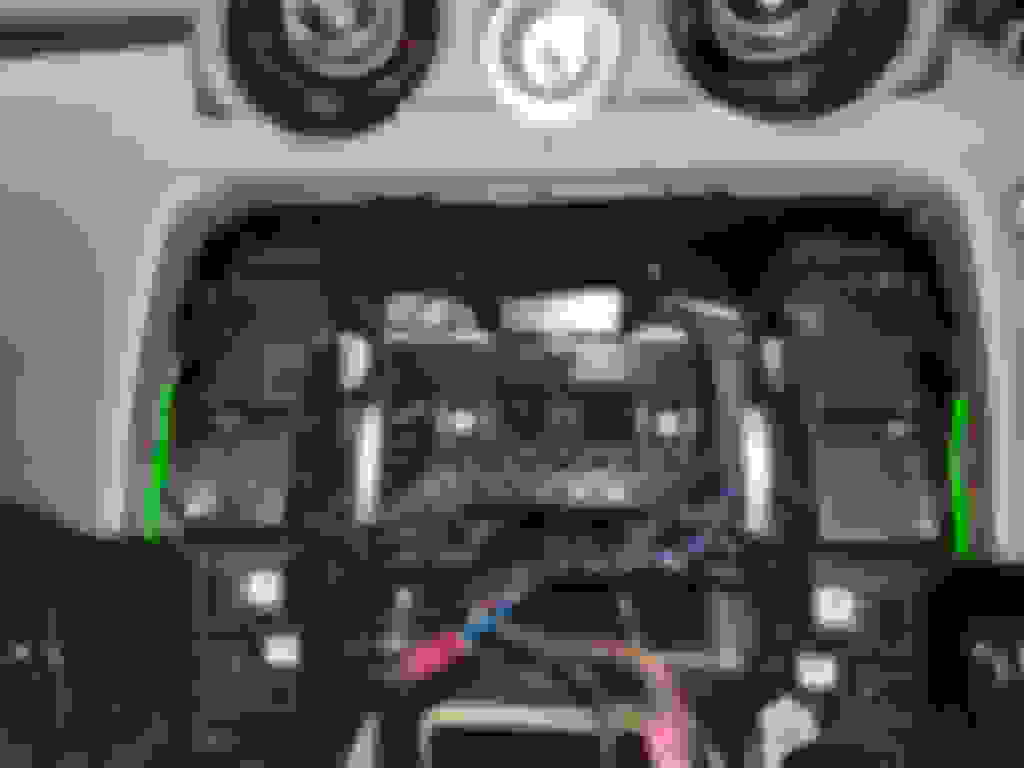
That is as far as you need to go in these instructions to be able to move the panel enough to get the centre reinforcement out by lifting/manhandling the upper instrument panel. Be careful not to snag on the cables.
That is it for the disassembly. You should now have something that looks like this:
Transfer the square metal captive clips from the old centre reinforcement bracket to the new one where appropriate. Not all will transfer. You can test assemble the DVD reader, FCIM and touch screen metal bracket to see which clips need transferring.
Fit the new centre reinforcement bracket to the car. The cables go through the top right hole.
Now is the time to get out the Dremel with a cutting disc and remove two brackets from the upper instrument panel where shown. Cut them flush along the inside edge (see before and after photos):
Before (both sides are the same)
After cutting
Also modify the upper bracket on the two floor vent upper leather trims by cutting the top half of the upper bracket off as shown:
Left modified, right original
Now just follow your disassembly instructions in reverse, ticking off each again as you go.
When you come to insert connectors always double check they are fully engaged and locked securely as it is easy to think you have connected it but really it is still loose. I find the bit grey connector that connects the floor console harness with the body harness on the right-hand side needs an extra push to lock in place.
There is nothing else to note about the reassembly – just follow all the steps in reverse.
I will mention that a brand new FCIM is supplied without the upper clips used in place of the upper screws on the old FCIM. I omitted those as I could not locate the part – a few wraps of cloth Tesa harnessing tape around the plastic leg where the clip would mount was enough to securely hold it, and the outer trim bezel will keep it in place anyway.
Quite sure this is beyond my capabilities, but I'm certainly glad you were able to get it to work. I was wondering if this could be done to my '17 XJL and now I know. Wonderful job and it looks great!
If you have the IAM-based system you will have to go for an Android overlay as the only 10" option. If you have the IMC system though then AFAIK there is no Android upgrade possible as the hardware to overlay doesn't exist with those. (Plus it would be much, much easier and cheaper to just make a bracket that allowed the OEM screen to fit into the existing fascia bracket as the IMC hardware is identical for both screen sizes.)
Yes, a 2014 would use the IAM, so the Android overlays are the way forward there.
I'm keeping an eye on the progress in the other thread as I might do that to my 2010 XJ if the usability is good.
I believe the InControl Touch is the NLI system which still uses the IAM but has the InControl-style quadrant home screen rather than the vertical one? If so then sadly not - you'd need to look at the Android overlays for that.
I'm not familiar with the F-Pace though so it may not be IAM. One way to tell is to remove the screen and see what it looks like.
The installed maps must be update to a recent version via here.jaguar.com prior to swapping the screens and re-learning the IMC variant. This is because the earlier versions did not include the 10.2" UI and it will not load or allow you to upgrade it.
I had this today when fitting it to my other 2016 XJ which was running older maps. I had to go back to the 8" temporarily to install the new maps then switch back again.
Once you have working navigation with the 10.2" display you can just update as normal.
Hi Dave Thank you for teaching us how to upgrade the screen,it's very helpful. But there is no tutorial to update the infotainment system on the internet.
Would you please tell me how to update the infotainment system(Phase 4) and get carplay by using SDD? I'll appreciate it very much if you would help me.
(Sorry for post this reply to a wrong thread)
Updating to phase 4 is complicated at the moment (early March 2020) as the facility to do so via SDD has been suspended due to issues. It currently only allows phase 2.5 updates.
It can be done via Pathfinder, but it requires a bit of creative tweaking. I've only managed it the once while playing, and don't have as much experience with Pathfinder yet so I'm hesitant to share what I did just yet.
My advice today would be to wait for JLR to release the candidates back to SDD again. Their current ETA is "in March 2020" so it could happen tomorrow or it may be a few weeks. Once that has happened it will be easy again (just follow the instructions it gives you to to put the files onto a USB 3 drive and then download to the car).
If you are already 19A or later you will have CarPlay functionality but it may be disabled if the smart phone pack was never enabled. I have just noticed that I didn't put the CCF bit that configures what third party apps are available to you in my software post above, so I will need to hook back up to a car and grab that info.
I mentioned in the first posts that the IPBM module provides the HMI for all the camera functionality rather than the IMC, so we need to update its software so it knows it needs the 10.2" UI and not the 8" one. It also needs to know how to interpret the various CAN messages that are sent out by the other modules, like the AC control panel, and so it understands the "activate camera" soft button on the new touch screen UI.
After various trial and error attempts I have come to the conclusion that you need an IPMB with an existing software version of 20 of later.
If you have the 360 camera system, the new part for the XJ is C2D55068. WERS is JJ32-14F026-AC.
For just the reverse camera, the new part is C2D55071. I am unsure of the WERS for that part.
That part is fitted to various other JLR vehicles, and most used ones are from RRs or E-Paces (the 360 variant is the only module fitted to the E-Pace).
All the 2016MY XJs I've worked on have been fitted with FW93-14F024-AE to AJ, and have been fitted with the 360 camera system.
Both LWB and SWB use the same hardware, but rear camera only and 360 camera system have different hardware.
The calibration software is different between LWB and SWB. This appears to be indicated by an major revision letter of A for SWB and B for LWB to the as-fitted WERS (the module however is the same). That is based on observation not qualified information.
New modules ship with the right strategry software but wrong calibbration data flashed so you need to reflash these on installation. Used modules will have whatever software was fitted to the donor vehicle. In either case it will need to be reflashed.
The process for doing this is simple, but there are some points to mention first:
1) I have bricked 4 IPMBs before I worked out the new/used module must have SW version 20 or later. It is printed on the label. It may be possible to update those on the bench, but not via CAN in the car which is my method.
2) The HW version has been 04.01.04.01 on all those I have used.
3) FW93-14F026-XX can't be reflashed to this software, so keep your current module as a backup or sell it.
4) I have had no success flashing the LWB calibration. I am unsure why. I have flashed the SWB calibration to a module fitted in a LWB car successfully, and the only difference appears to be a slight distortion to the rear or the side image where it stitches to the rear image (as you would expect). TBH the cameras are so poor anyway, and completely useless in the rain, so it hasn't been an issue for me.
Always attached a suitable external power supply to the car before attempting any software programming. A simple battery conditioner in supply mode may not be able to provide enough current. You need to maintain 12.6V minimum at all times. I really mean that - do not let the voltage drop during programming.
The programming process is shown in the steps below.
IMPORTANT NOTE - the part numbers shown are for the 360 camera system variant. I have no experience with the rear camera only variant so cannot compare the part numbers.
I am hoping that by providing original and new numbers for the 360 variant you may be able to infer the equivalent by interogating the part fitted to a rear only vehicle. (Use the parts summary icon on the main session page.)
1) Fit the new module
It is located behind the rear right passenger seat back. There is a cutout in the bulkhead lining which exposes it. Two 10mm nuts secure it to a bracket.
2) Start an SDD session and select Diagnostics.
3) Modify the as-built data for the target vehicle and change the fitted hardware WERS number.
The as-built data file is stored in:
C:\Program Files\Jlr\Common\Xml\IVSAsbuilt
It is downloaded during the new session process.
Copy and paste the file named YOURVINHERE_MODULE_RECORDSET.xml so you have a backup.
Open the file named YOURVINHERE_MODULE_RECORDSET.xml.
Search for IPMB and make a note of the fitted part number. That is the engineering number of the part fitted at the factory, not necessarily the same as the label on the module as they are installed pre-calibrated to save time.
It should be FW93-19H423-AX (SWB) or FW93-19H423-BX (LWB) - 360 variants. Rear camera only will have different versions here.
Change it to JW93-19H423-AC (SWB). Do not change to a BX revision as it will fail to flash and brick the module.
Save the file and set the read-only flag on it. This will prevent SDD from replacing it later in the process.
4) Start the configure the existing module candidate. SDD will detect the software versions are different and download the latest versions from the JLR servers.
5) You will see a screen that shows the current and new software versions. If happy with the changes save them to the vehicle.
This summary screen is the last chance you will get to check everything is ok before starting the reflash.
You should see the following (at the time of writing this, remember 360 variant):
HW part no FW93-14F015-AD
Assembly part no JW93-19H423-AE (this is the pn we set in the as-built data, but we set it to AC to force the software downloads)
Signal calibration part no JJ32-14F016-AA (this is the software that interprets and sends CAN messages, etc)
Strategy software part no JJ32-14F017-AD (the main software)
Calibration data part no JW93-14F022-AC (this is the calibration data for the XJ)
The calibration data part no must not be a B major revision or it fails. I am unsure why, but it has every time for me so if you follow these instructions at least you'll have a working module at the end.
That is basically it - the software download takes about an hour then everything is done. Afterwards everything should work as if it was a 2019MY car.
I have some feedback regarding "Part 4 - Disassembly instructions, Step 13" above and I can no longer edit that post so I am adding it here:
To recap what I had said above:
Step 13 (removing the vents) ignore the instructions, there is a much easier and quicker way to remove them. If you don’t have blue illuminated vents you can pull the central ‘globe’ part out by just pulling on it hard, and then release the 4 black tabs that hold the silver outer trim in place with a small screwdriver and wedge a piece of card in each so it stays released. Then just pull the silver trim out and you can easily release the 4 metal tabs to pull the vent out. If you have illuminated vents you can still do this, but the ‘globe’ will remain attached by the two thin wires so don’t pull too hard or you’ll tear them.
The reason why I couldn't follow the workshop method of hooking the vents out behind the rear bracing was that the metal clips on the first car I did with with were well wedged in place (a square metal lip against a square plastic guide so it would not pull over it and release).
On the second car I have done this upgrade on I was able to hook them out in the correct way. I did this by changing the workshop manual technique slightly, and am fairly confident this would have worked on the first car had I known at the time. My new technique for easily removing the vents is now:
1) Cut a 30cm piece of insulated single core cable (or similar strong wire that won't cut into the plastic) and bend the last 5cm over in a loose 'U' shape.
2) Fully open the vent and feed the wire in at the NW quadrant and then behind the vertical plastic support and back out the NE quadrant using longnose pliers to grab it.
3) Repeat 1 and 2 again with the SW/SE quadrants.
4) Grip the wires tightly and with one hand push the chrome edge ring hard back into the dashboard before quickly yanking hard on the wires.
They should pop straight out as intended. I think on my first car I needed to push the ring in when pulling on the vents so the metal clip was not pressed up hard against the plastic guide. I've not seen the special tool JLR supply for this purpose, but I wouldn't be surprised if that had a little hook on the bit that goes behind the vertical support to allow you to push back on them and then pull.
Removing the vents was the most frustrating part of the whole process so hopefully that technique will help someone else facing that task.
 01-11-2020, 02:33 PM