When you click on links to various merchants on this site and make a purchase, this can result in this site earning a commission. Affiliate programs and affiliations include, but are not limited to, the eBay Partner Network.
Air Suspension Coil Conversion Observations & Tips
I just completed another X350 air- to coil-spring conversion, and was reminded of a few common challenges and thought it would be worthwhile to record them here for the benefit of myself and others who may undertake the conversion in the future.
This week’s car is an early 2004 Vanden Plas with four ride height sensors. The conversion is essentially the same on all the X350 and X358 models.
Front End Coil Conversion:
The front end conversion is relatively straightforward. The Arnott instructions usually work fine. The one thing I do differently is that I do not remove all four of the air spring top mount nuts before I remove the shock lower bolt. I remove three of the nuts and leave one nut threaded on loosely to prevent the air spring/damper from falling unexpectedly. It’s heavy enough to injure me, or the brake hose or ABS wheel speed sensor harness if it falls unexpectedly. Once I have the lower shock bolt out, I hold the air spring/damper with one hand, then reach up over the fender and remove the remaining top nut.
The most common challenge is the lower damper/shock absorber bolt, which can often be very difficult to remove. Even with plenty of penetrant given time to soak in, my 1/2 inch battery- and air-powered impact guns will not always break one free. A long breaker bar with an added pipe extension is occasionally necessary. Take care to ensure that your T60 Torx bit remains fully seated in the head of the bolt to reduce the risk of stripping the bolt head. The Arnott Industries C-2745 kit now includes new lower shock bolts with hex heads.
To remove and replace the front air spring/damper, it is not necessary to disconnect the brake caliper or to remove the caliper mounting bracket and rotor. However, for the few minutes it takes to do so, the reduction in weight that you have to deal with when reconnecting the vertical link to the upper control arm is often worth the extra time. Regardless of whether you decide to disconnect and remove the brake components, do disconnect the ABS wheel speed sensor to reduce the risk of damaging the harness or sensor. The connector is right at the sensor.
When installing the new spring/shock unit, you may need to use a long prybar on the lower control arm in order to get the lower end of the shock up and over the control arm and into position. I put a knee on the prybar and let my weight press down on it so I can use both hands to wrestle the shock into position.
I highly recommend replacing your front upper control arms/ball joints at the time of the conversion, since the air springs/dampers must be removed to provide the necessary clearance for the control arm bolts to be extracted. And you may as well replace your stabilizer bar links also, since you have to disconnect one end anyway.
Rear End Coil Conversion Challenges:
Now on to the main purpose of this post. By far, I have found the rear end conversion to present the most challenges. In fact, I can’t recall ever needing the help of an assistant when doing the front conversion, but I have frequently found an assistant helpful or necessary on the rear.
An important tip in the Arnott videos is to put the transmission in Neutral prior to disconnecting the battery. Another helpful tip is to also disengage the Electric Park Brake. This means it is critical that you chock the front wheels if working with the vehicle on the ground rather than on a lift.
Disassembly is rarely a problem, although I have had a couple of lower shock bolts that were corroded and did not want to come out. Sometimes you need all the tricks: penetrant, impact, shock on the bolt head and hub, leverage, heat, etc.
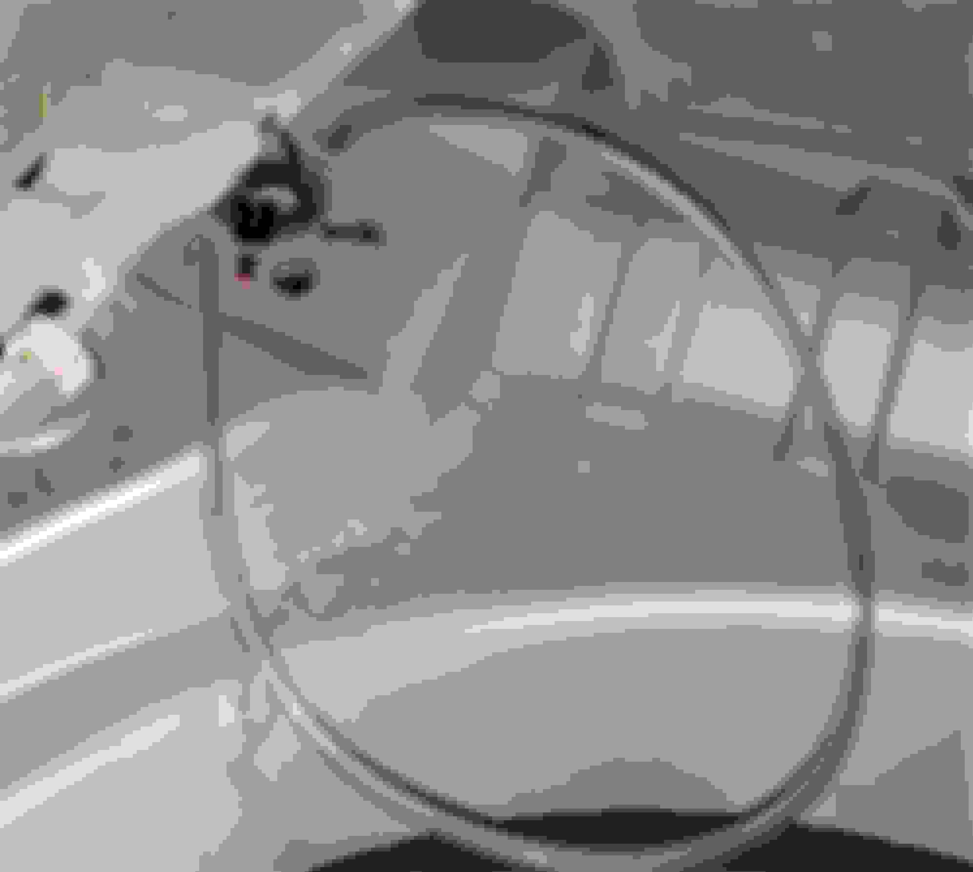
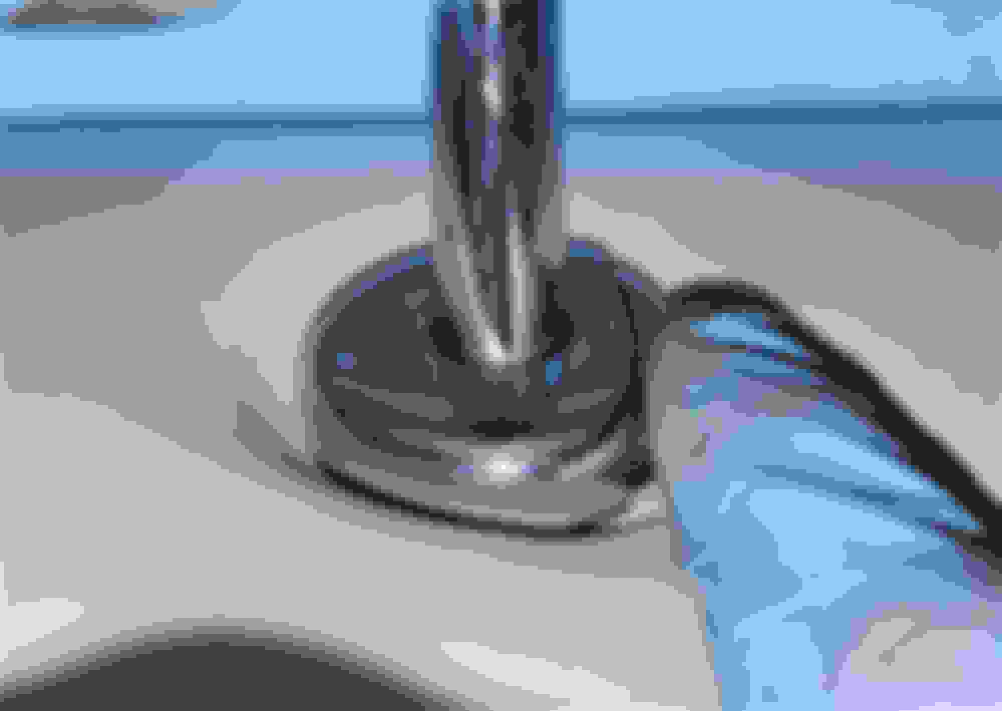
The first frequent challenge when installing the new coil/shock unit is that once you lift the unit up into the recess in the body, you can no longer see the holes for the mounting studs, and finding the holes by “feel” is not easy, due to the cumbersome weight and bulk of the coil spring/shock. A simple trick to make this process much easier is to thread a section of � inch I.D. vinyl tubing through the two larger stud holes in the body. Thin-walled rubber tubing would work also, but the vinyl tubing slides easily through the holes. Thick-walled rubber tubing won't fit:
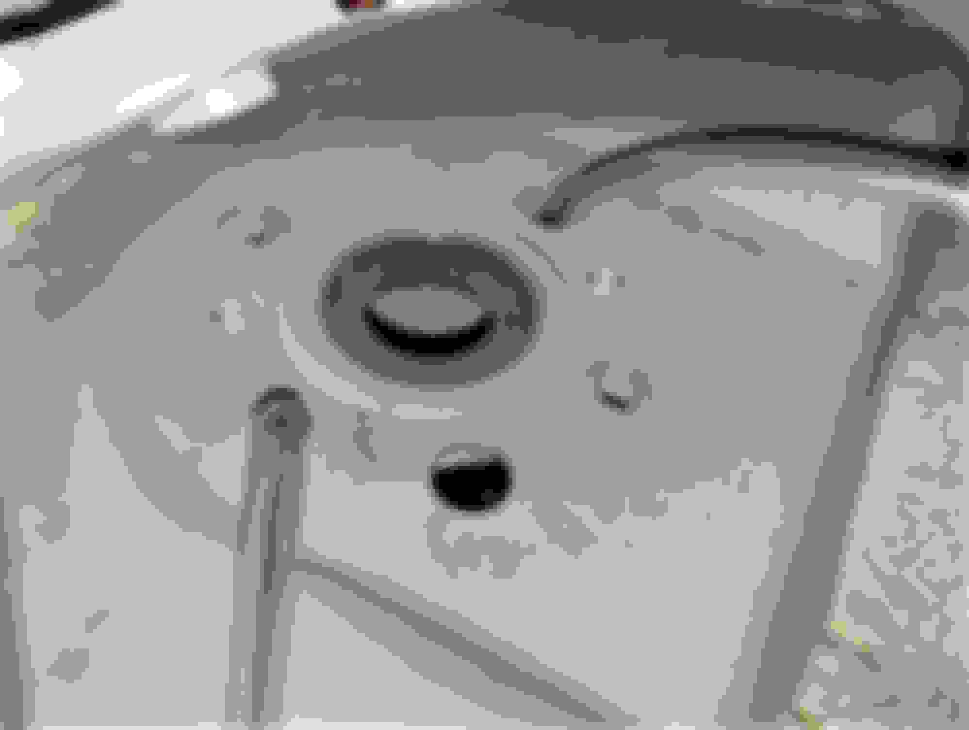
Stand the shock up under the car and orient the lower bushing so it will mate correctly with the hub when it is raised into position. Then attach the corresponding ends of the vinyl tubing to the studs that will fit through the larger holes in the body:
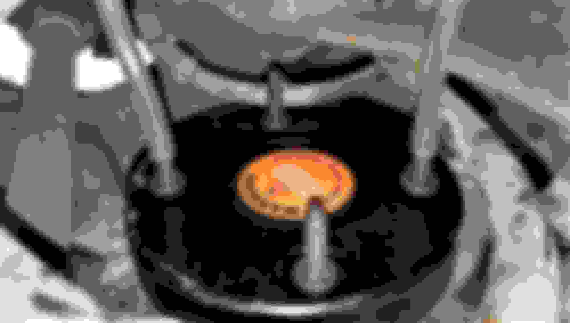
NOTE: As of September 2022, Arnott has revised the upper coil spring mounts to a billet aluminum design:
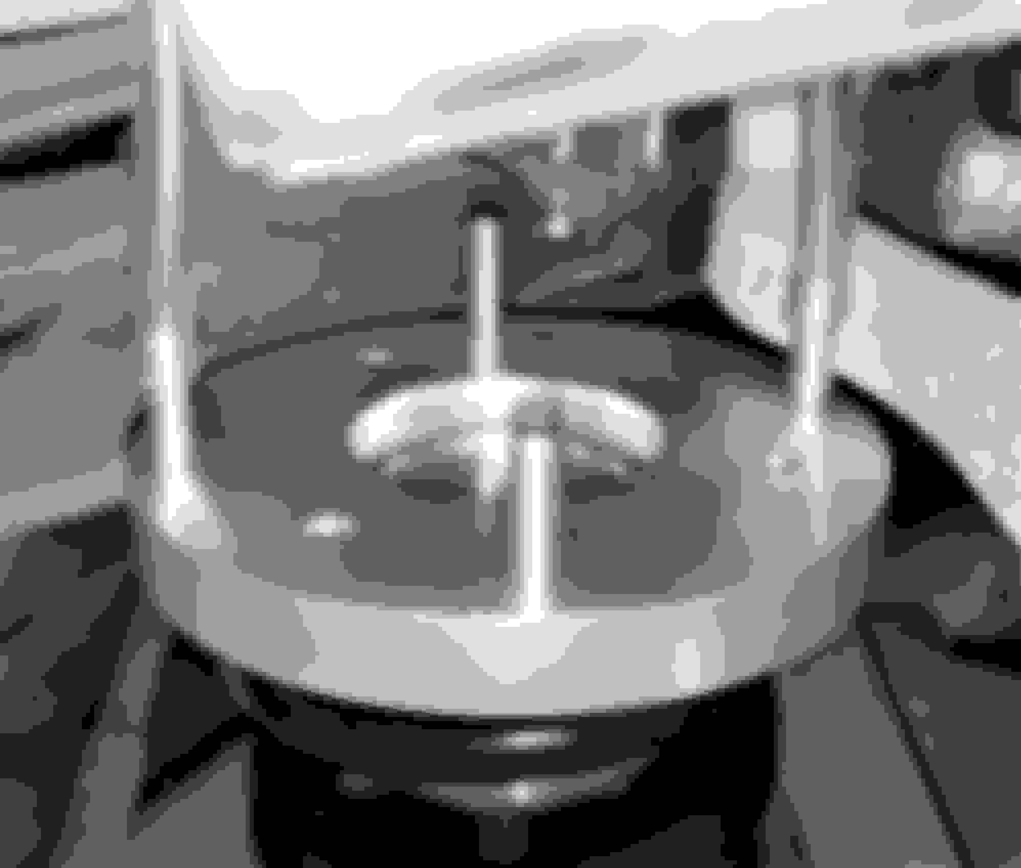
Have your assistant gently pull up on the two ends of the tubing as you raise the spring/shock assembly up into the recess. The tubing will guide the two studs right up into the larger holes. Your assistant can then thread on one of the nuts and the tubing can be pulled off of the two studs. If you do not have an assistant, use a piece of tubing long enough to hang over the rear fender so you can gently pull on the tubing loop as you raise the spring/shock. Once it is up in position, prop it up with a small jack or any other tool that is handy so you can thread on the top nuts:
If you do not have an assistant, it helps to support the coil spring/shock unit with a small jack as you raise it into position. When I have the unit raised to within three or four inches of the top, I gently pull on the vinyl tubing to remove any slack. Then I use one hand to wiggle the studs up through the holes and then use the other hand to raise the jack high enough to prevent the studs from falling out of the holes. Trying to raise the unit all the way with the jack will usually just run the studs into the top of the suspension mount with the studs misaligned:
Rear Lower Shock Absorber Bolt Installation:
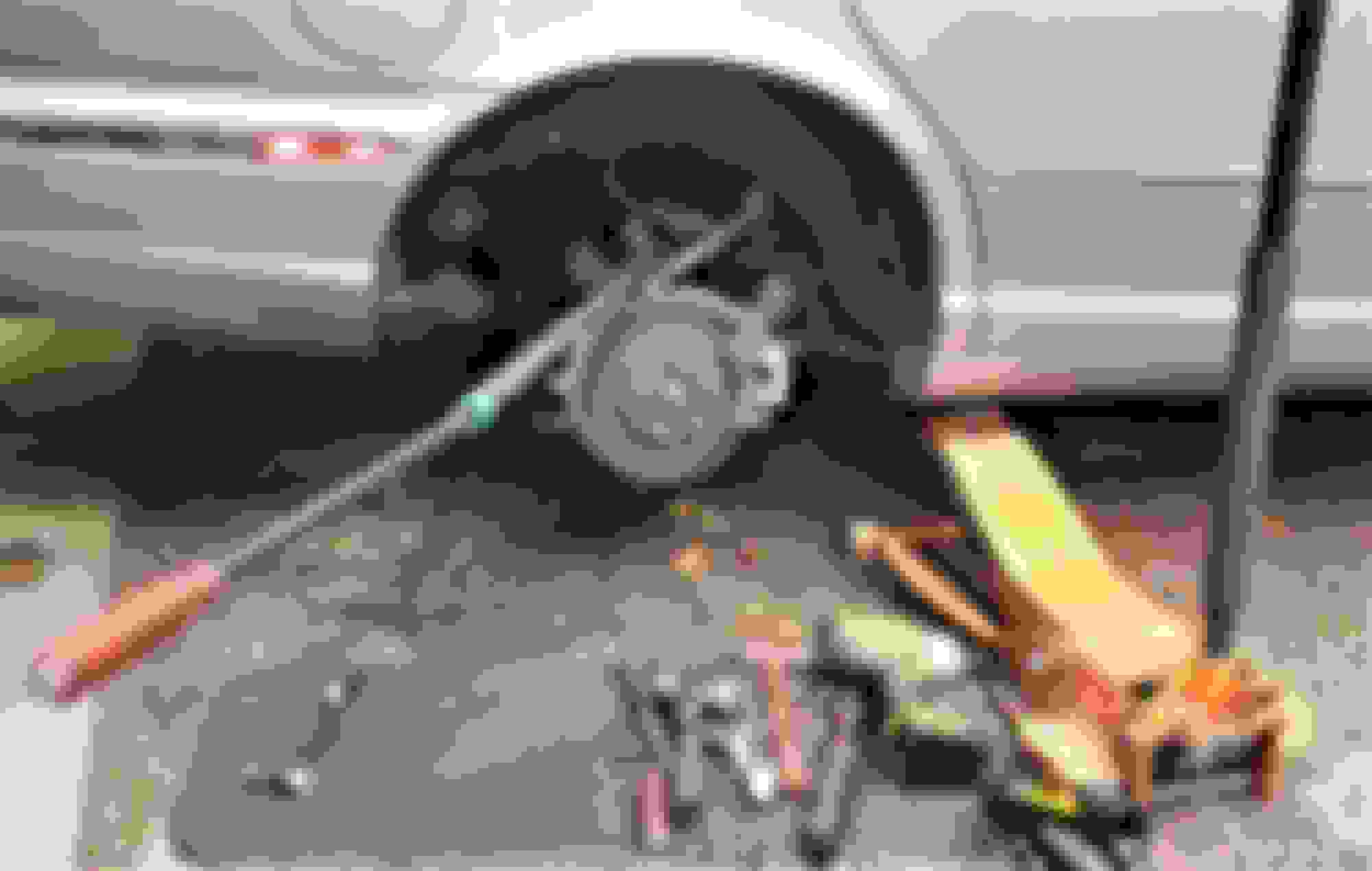
Another frequent challenge comes when you are ready to install the lower shock bolt. The Arnott instructional video makes it look like you can just push the suspension down by hand to line up the shock with the bolt hole. Sometimes you can. However, even with the stabilizer bar link disconnected at one end, which is critical, I have rarely found it to be as easy as the Arnott video makes it appear. Usually, some leverage is required to move the suspension downward far enough for the shock bolt to be installed. There are a few ways to accomplish this. One is to use a long pry bar or equivalent on the lower control arm. The end of the bar can hook up under the fulcrum and then be levered downward on the top of the control arm. The disadvantage of this method if you are working with the vehicle on jack stands and jacks, is that the handle end of your pry bar may contact the ground before the suspension is low enough to align with the lower shock bushing.
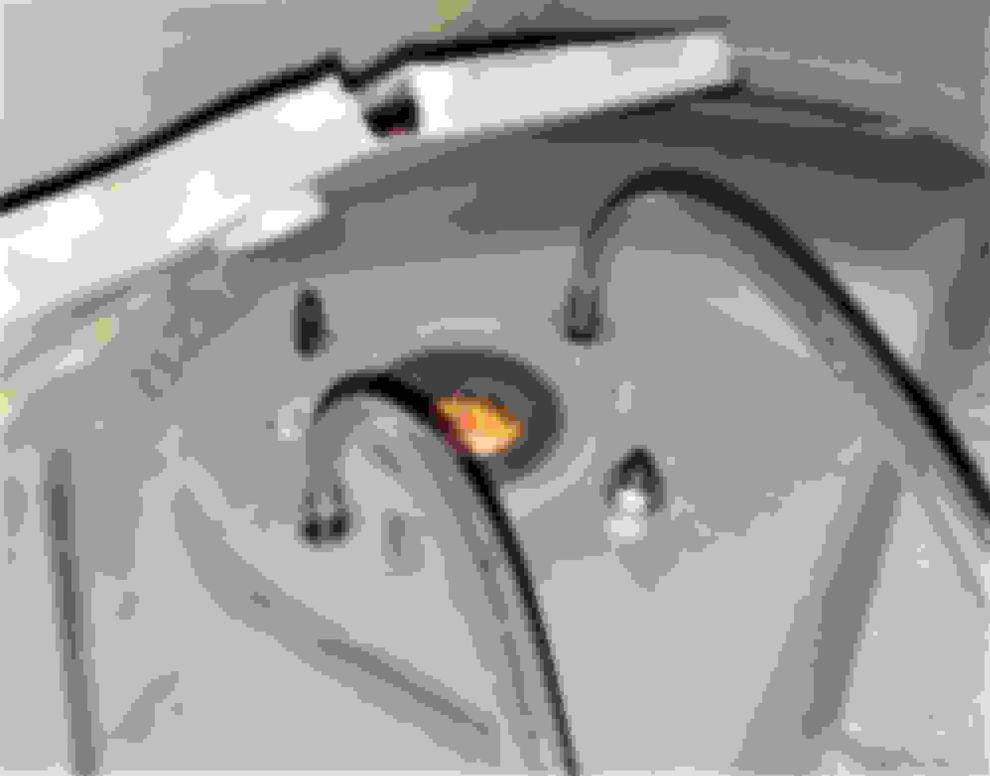
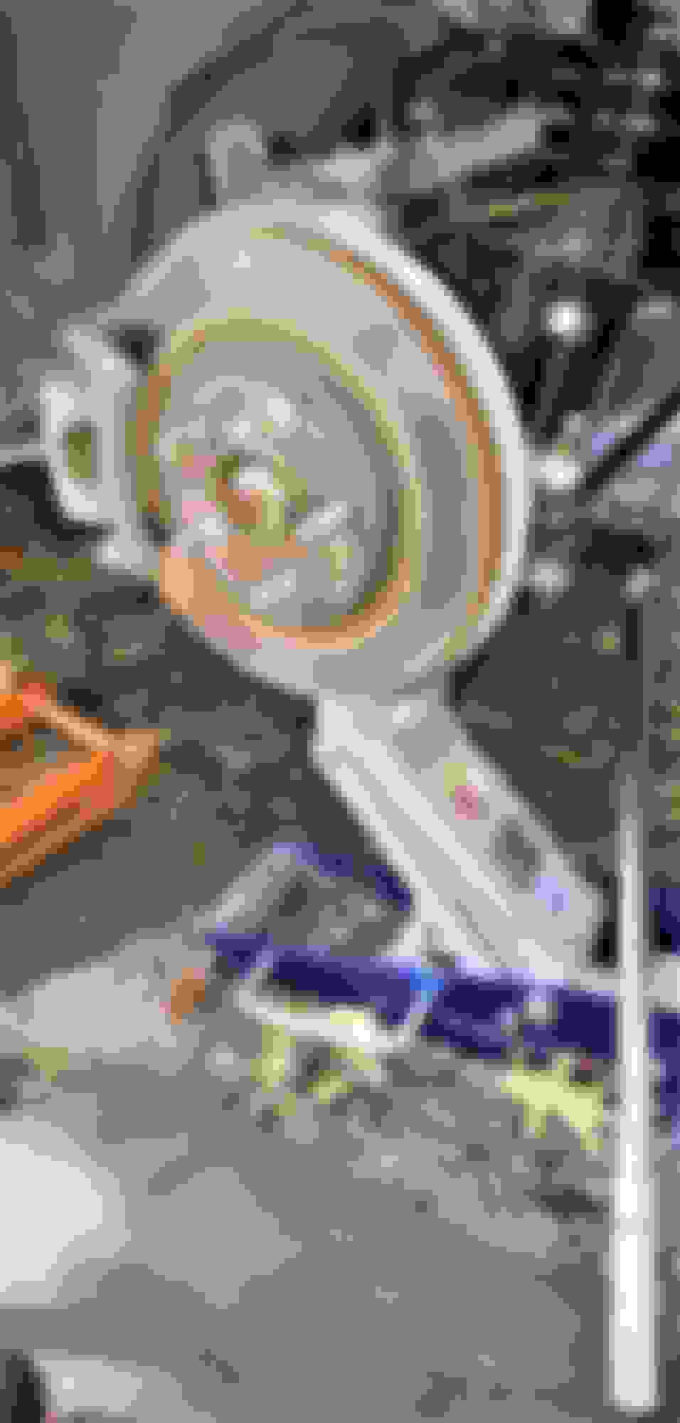
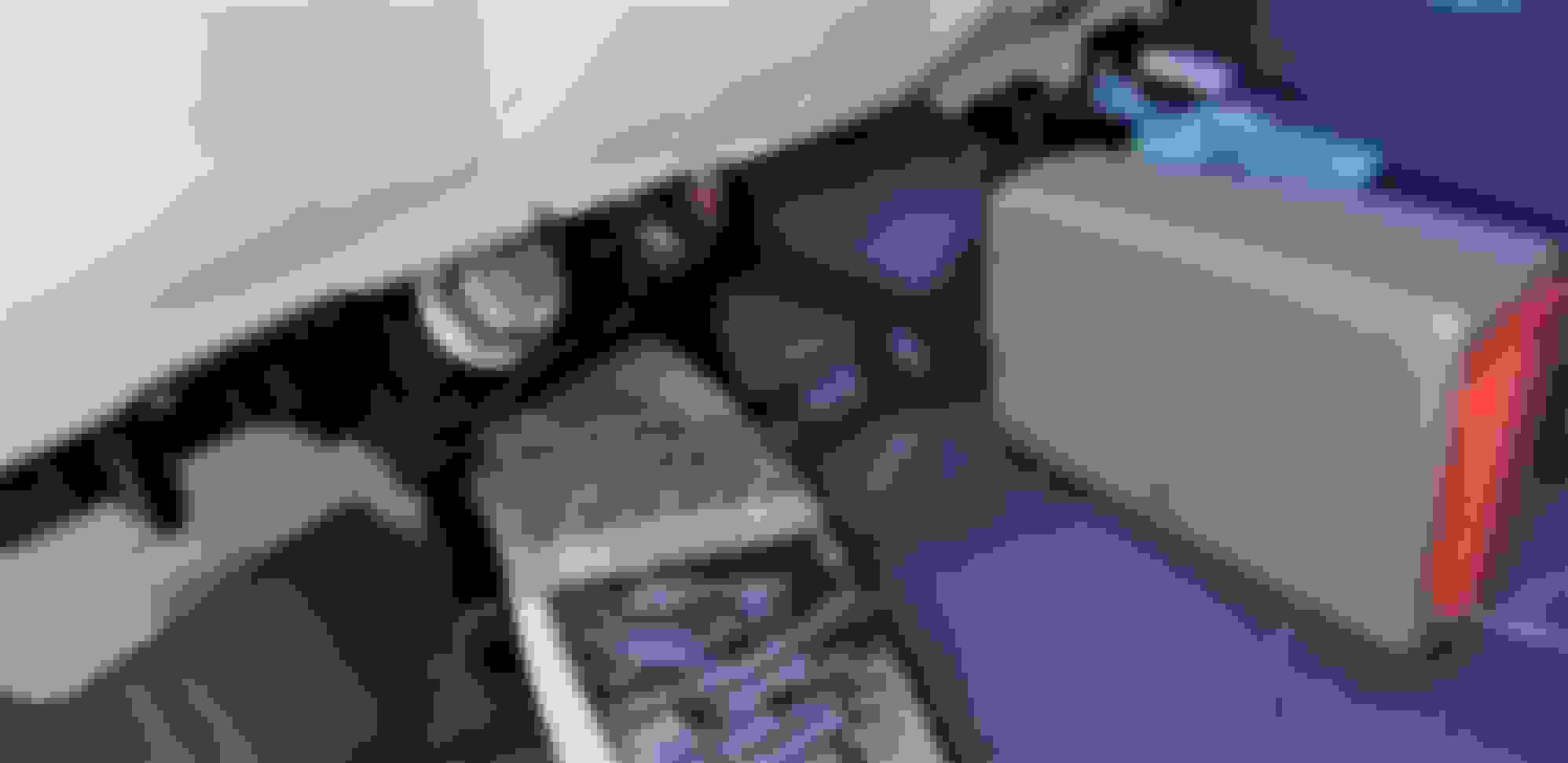
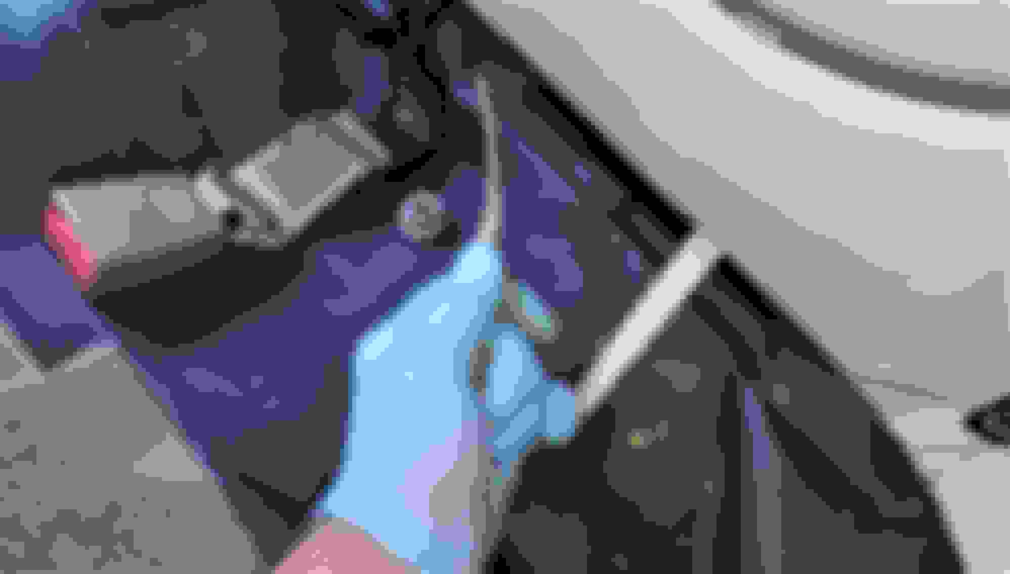
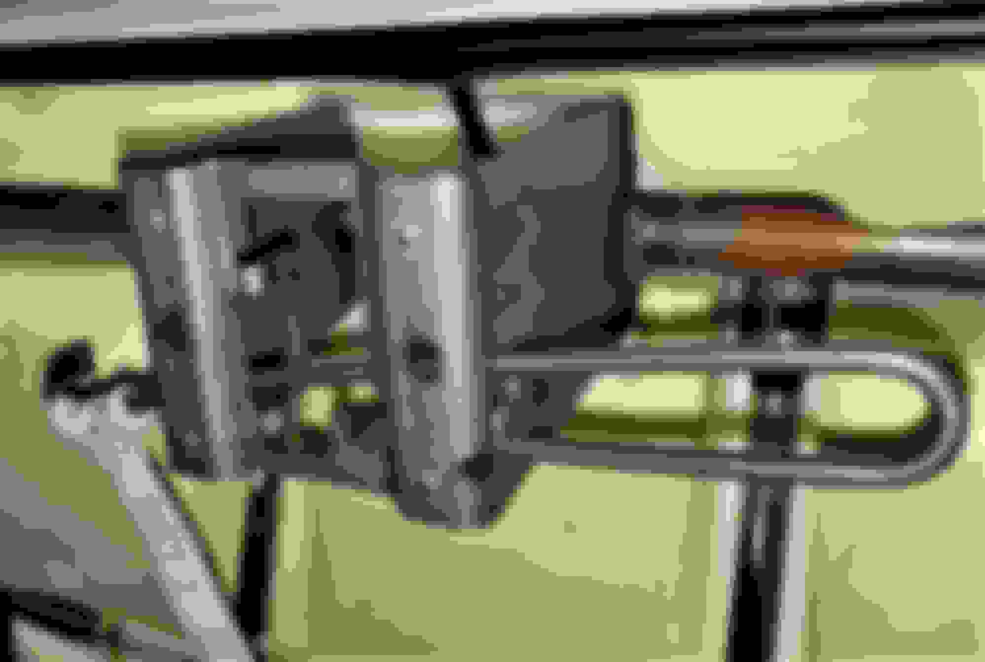
Another method that overcomes this problem is to use your lever on the upper control arm. First, unclip the ABS wheel speed sensor harness from the upper control arm:
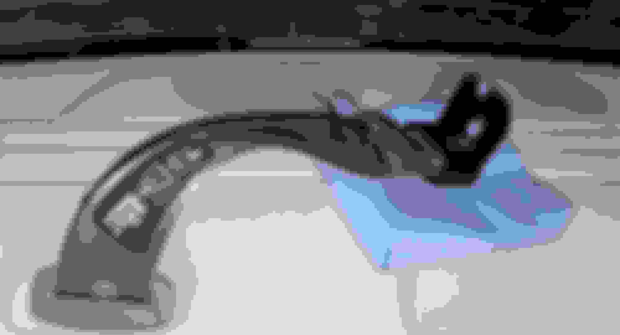
Now, insert your pry bar into the upper control arm so you can lever downward. Take great care not to apply any pressure on the brake hose. Note how I routed the pipe below the brake hose so it doesn't bear on the hose or the ABS wheel speed sensor harness as it is levered downward. Sometimes, I find that I need more leverage than even my longest prybar provides. I then use a section of pipe with the pry bar inserted into its end, and if necessary, have an assistant push downward on this long lever while I insert the lower shock bolt.
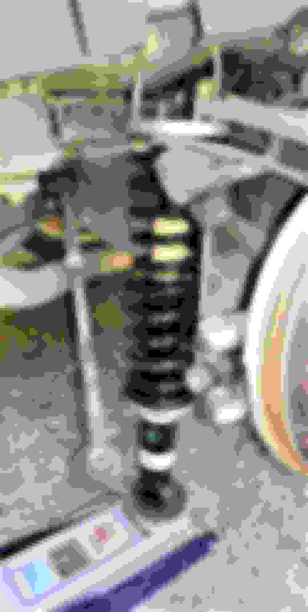
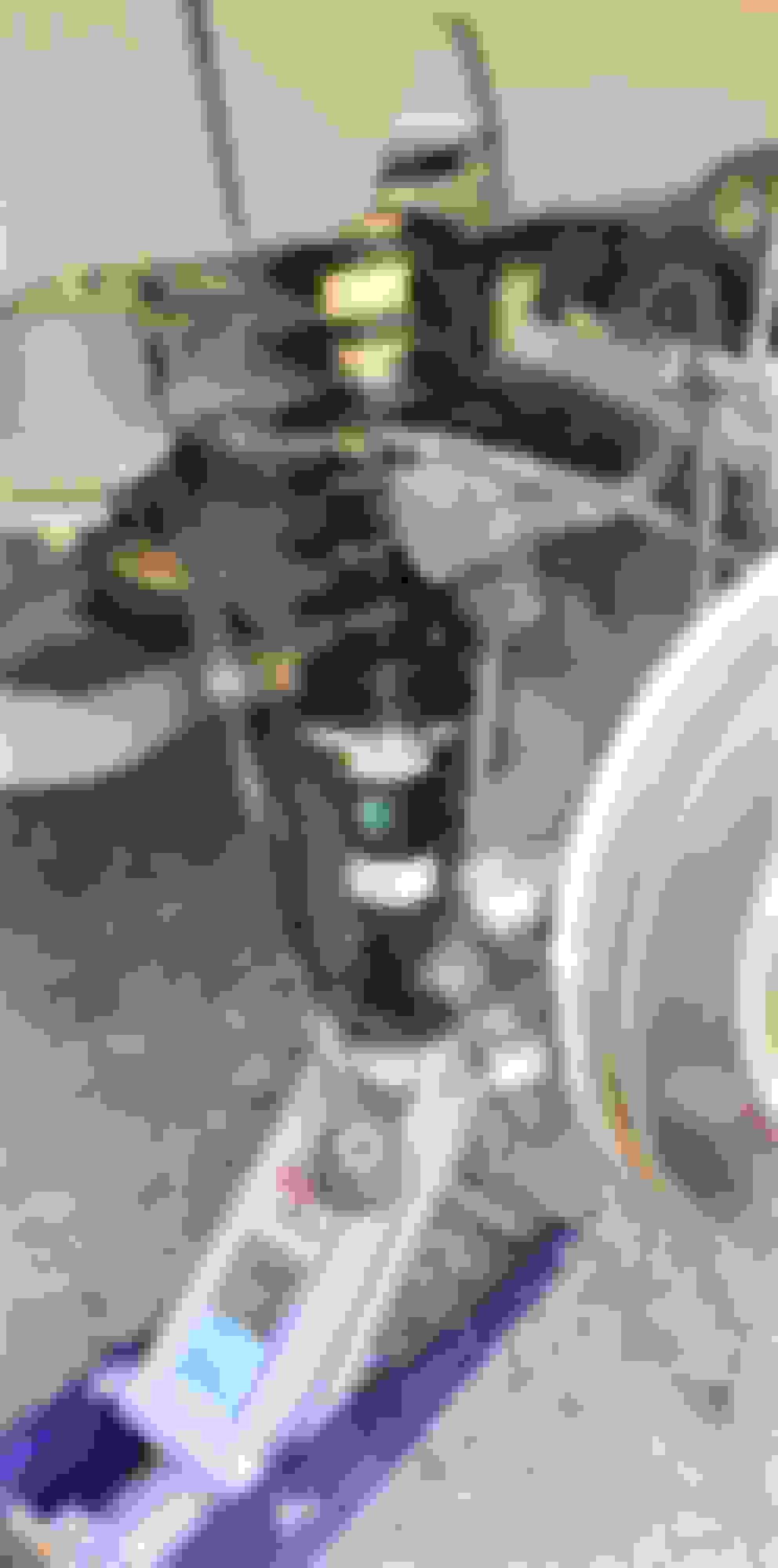
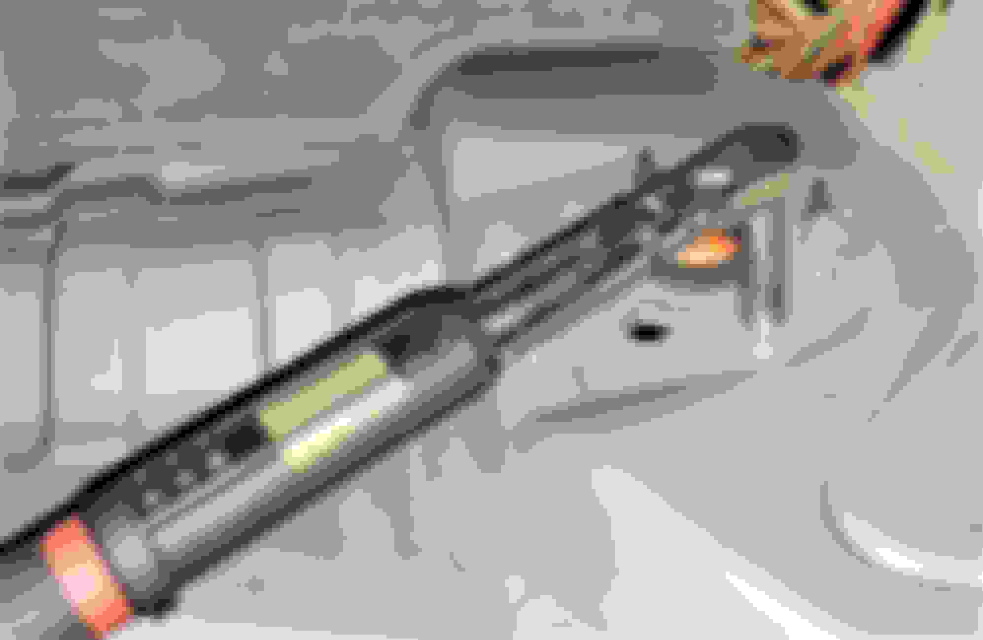
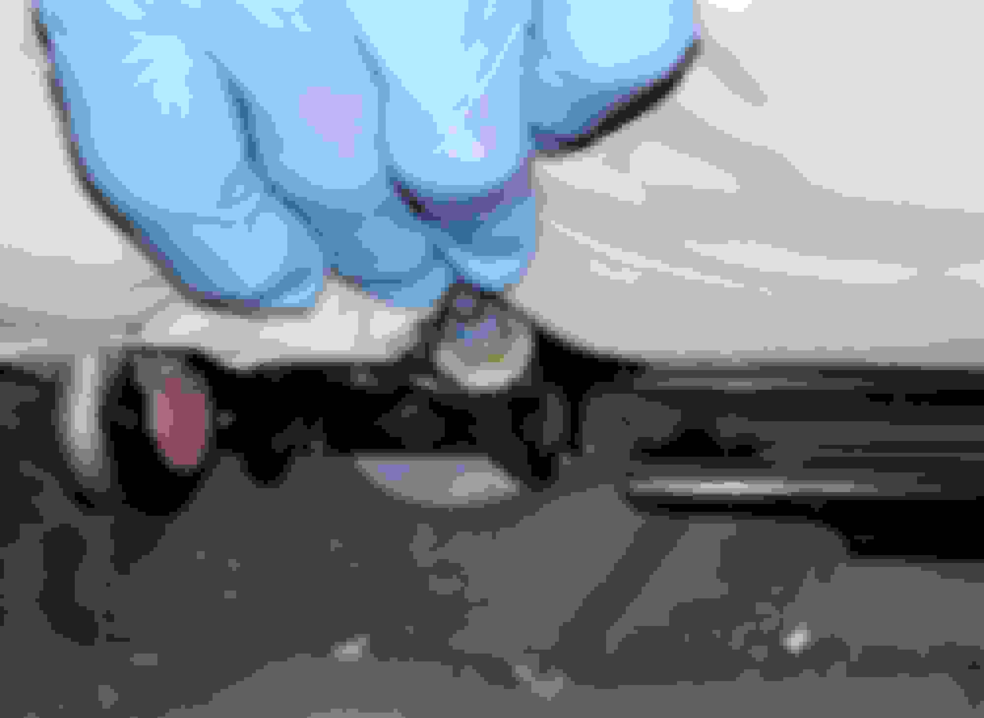
Another approach is to take an idea from the X308 knowledge base and use a small scissor jack to force the suspension downward. The X350/X358 scissor jack is not a great design, but with care it can be used, along with some short pieces of 2X4 lumber. Again, take care not to apply any pressure to the brake hose or ABS sensor harness: If you bend the brake rotor splash shield, it can easily be re-shaped later.
If none of these methods works, you may have no choice but to disconnect the upper ball joint from the hub carrier so you can get it low enough to align the lower shock bolt. I am not certain, but the Eibach springs/shocks now supplied with the Arnott kit seem a little longer than the earlier units, therefore requiring the rear suspension to be forced farther downward in order to align the lower shock bushing with the hub so the bolt can be installed.
Prior to torquing the lower shock bolt, use a jack to raise the suspension until the weight of the vehicle just comes off your main jack or jack stand. This preloads the shock lower bushing so it will be under correct stress when the bolt is torqued. The same is true if you are replacing any control arms or bushings – do not torque the bolts until the suspension is raised to its typical static position when the weight of the vehicle is resting on the tire.
Fastener Torque Caution:
One last tip: Some of our members have overtorqued a top mount stud nut, breaking a stud on their new coil spring/shock assembly. Take extra care when torquing the nuts. I do it in at least three or four steps, always tightening the nuts in an X pattern to prevent the binding of one or more studs in their holes. Snug the nuts up by hand with a ratchet just until you begin to feel resistance. Then torque each nut to about 1/3 the final torque spec, then 2/3, then very carefully all the way to full spec. Torquing these nuts by “feel” instead of with a good torque wrench can easily result in a broken stud or nuts that are too loose. So if you don't have a suitable torque wrench, plan to borrow, rent or purchase one. A friend and I compared my expensive calibrated Snap On, CDI and Precision Instruments torque wrenches with his new torque wrenches from Harbor Freight Tools and found that his were surprisingly accurate within the upper 80% of their range. And the prices are so low you may be able to justify purchasing a couple rather than renting from an auto parts store. With click-type torque wrenches, it is important to turn the wrench back to zero between uses to prevent premature fatigue of the spring(s) and a resulting loss of accuracy.
You will need at least two torque wrenches for this job. One for the upper coil spring mount nuts, and one for the lower shock bolts.
The torque spec for the front coil/shock-to-body nuts is 25 Nm / 18 ft. lbs. The spec for the rear nuts is 28 Nm / 21 ft. lbs. For these you need a torque wrench with a maximum range of no more than 90 ft. lbs., and ideally no more than 75 ft. lbs. According to the SAE, torque wrenches are unacceptably inaccurate in the lower 20% of their range. 18 ft. lbs is 20% of 90 ft. lbs., so that is the maximum acceptable torque wrench range for the nuts.
The torque spec for the front lower shock absorber bolt is 175 Nm. / 129 ft. lbs., and the spec for the rear lower shock bolt is 133 Nm / 98 ft. lbs. So you will need a torque wrench capable of measuring at least 175 Nm / 129 ft. lbs. Do not use this torque wrench to tighten the upper mount nuts!
All other torque specifications can be found in the Chassis section of the X350 Workshop Manual, which you can download for free from the X350/X358 'How To' / Repair & Maintenance thread in the stickies.
Rear Seat Cushion Removal:
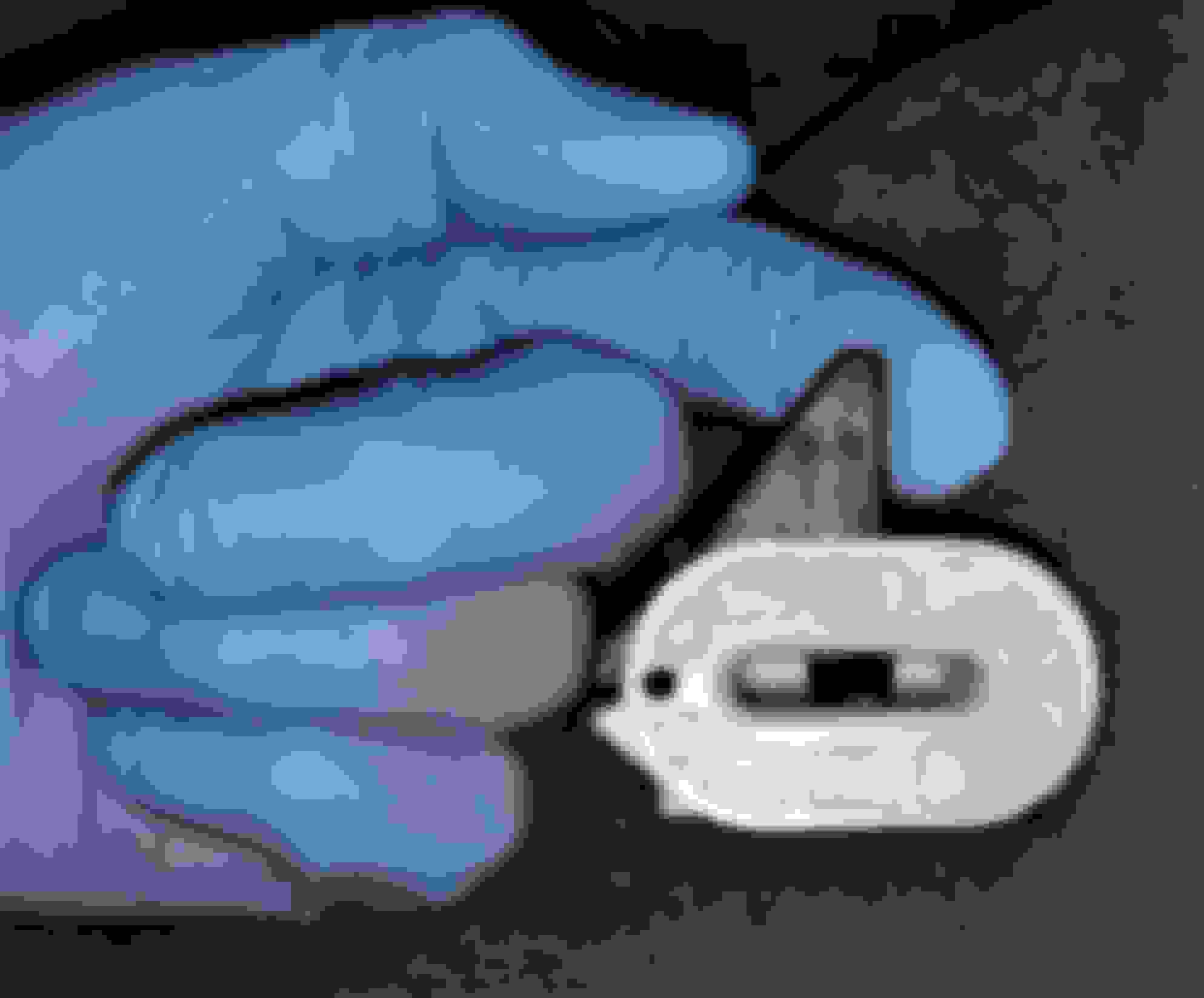
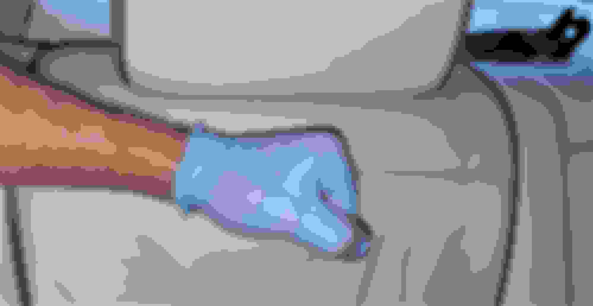
The final challenge you may face is removing the rear seat for access to the Air Suspension Module so you can install the Electronic Bypass Module (EBM), which fools the system so no air suspension fault warnings will be displayed on the Instrument Cluster. There are four latches or clips that secure the lower seat. To access the clips, you must slip your hand between the lower forward edge of the seat and the carpeted floor. All four clips are of the same design. A pointed lever must be pushed toward the left of the vehicle to release the clip from a U-shaped steel loop in the underside of the seat cushion.
There are two latches on each side of the propshaft/driveshaft tunnel:
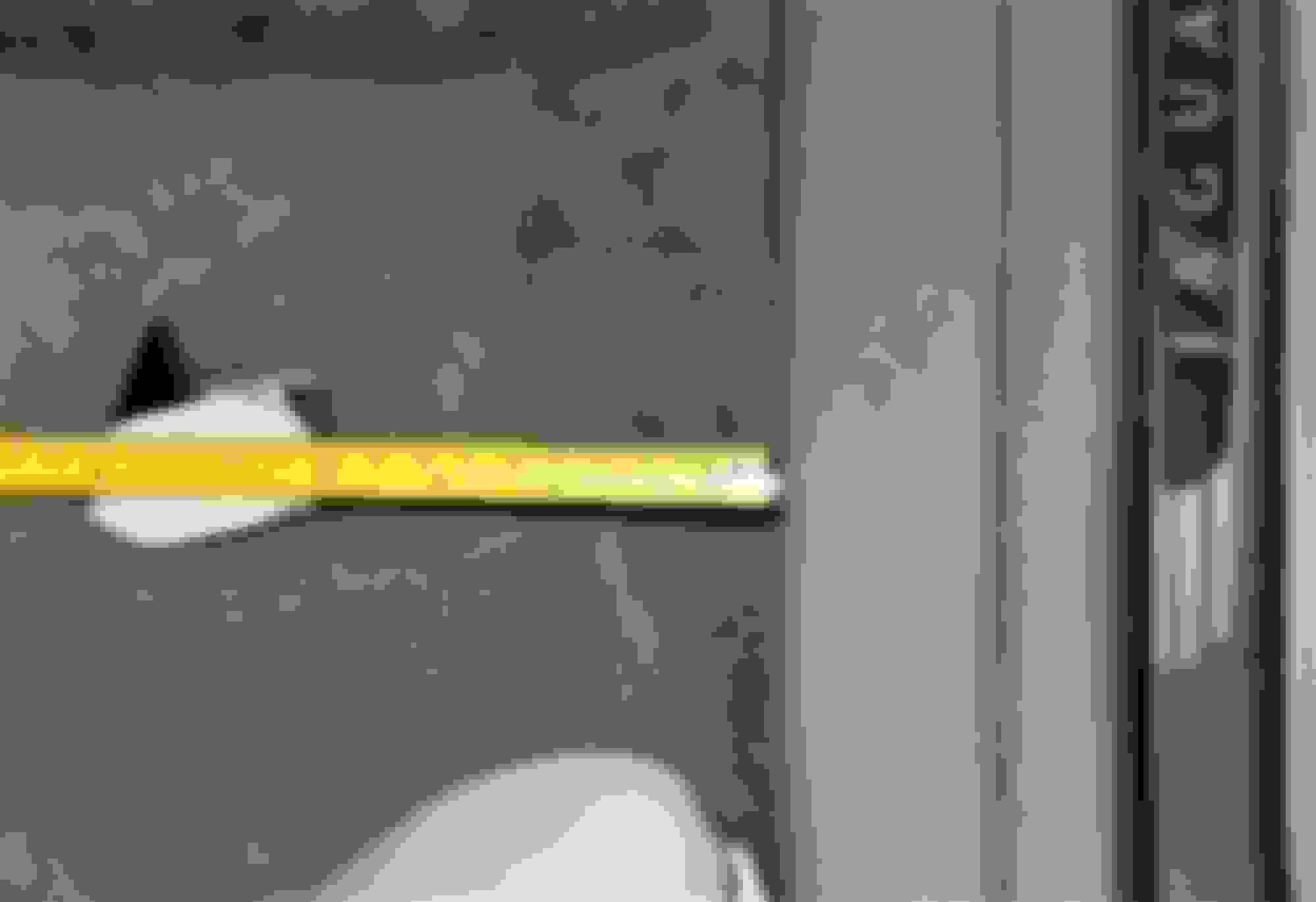
On some cars, especially those whose rear seat cushion has never been removed, the latches can be difficult to reach and release. There may just barely be enough room to force your fingers between the lower edge of the seat cushion and the carpeted floor. Knowing the latch locations is helpful. Measuring from the edge of the door sill plastic trim, the outer latch is approximately 5.5 in. / 14 cm toward the propshaft/driveshaft tunnel:
The inner latch is approximately 15 in. / 38 cm toward the tunnel:
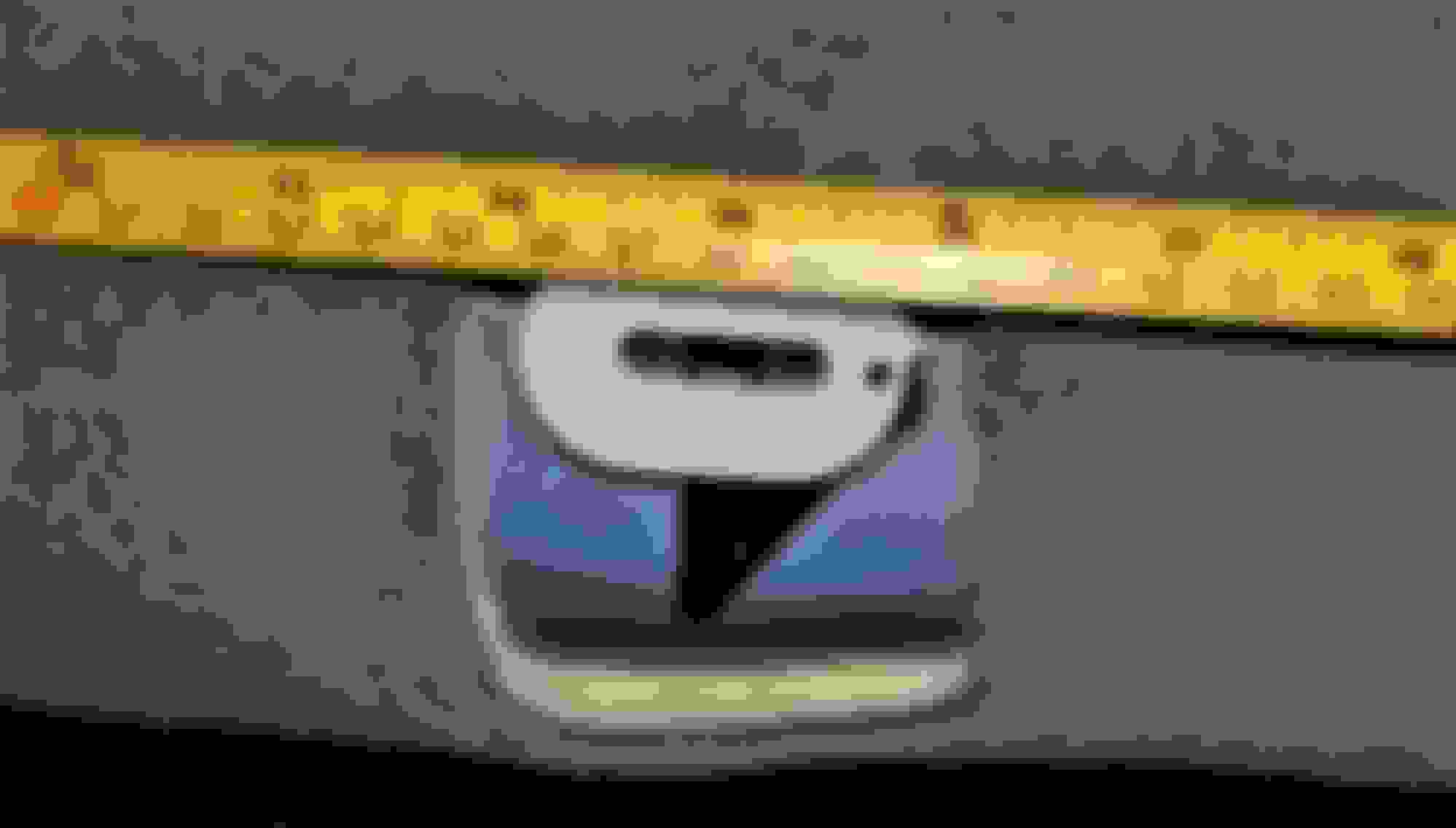
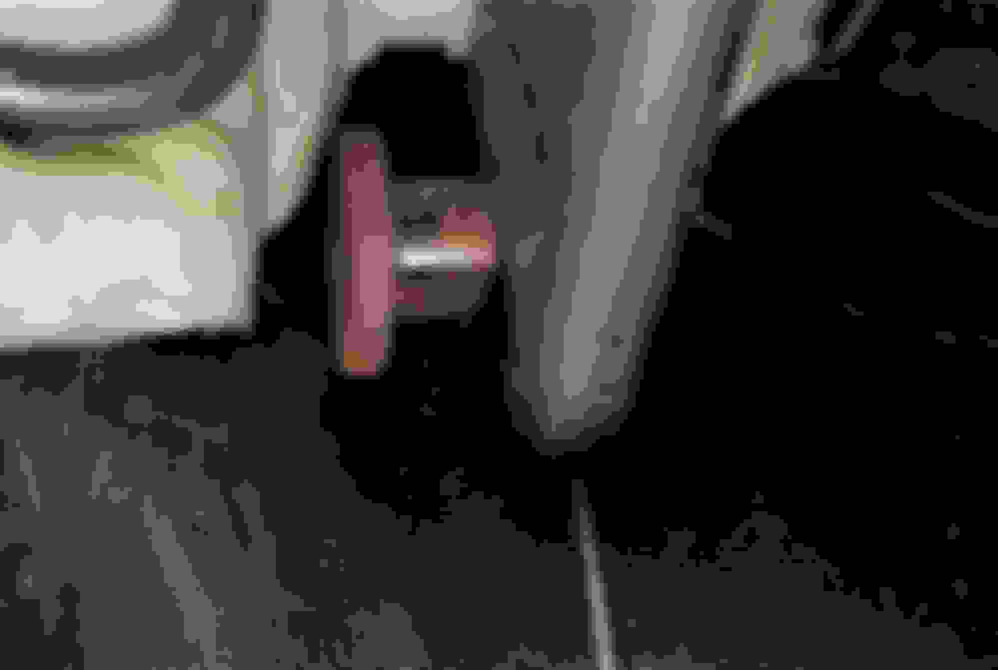
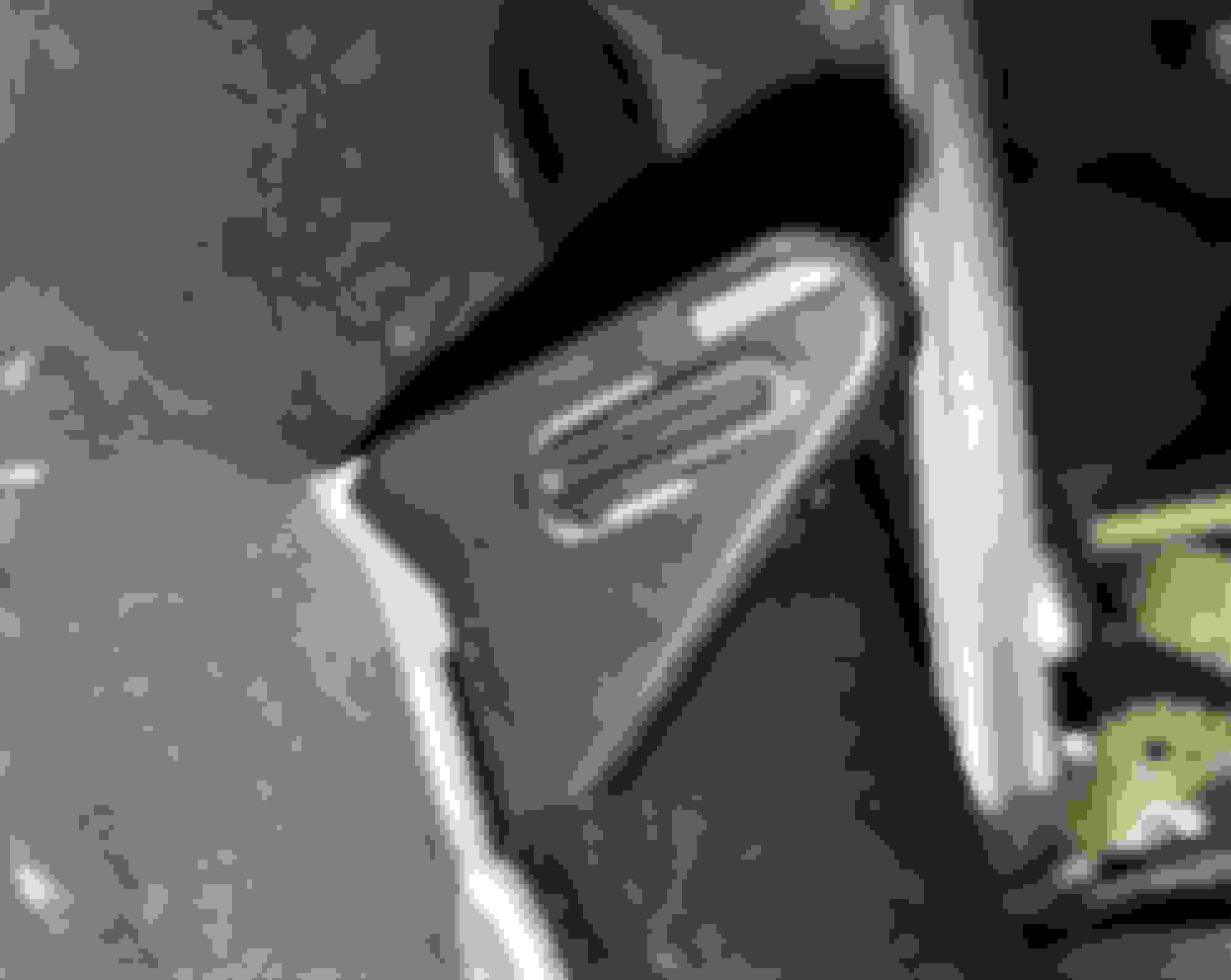
Here is a clip in its latched position:
The black plastic tab on the lever engages a U-shaped steel loop on the underside of the seat cushion:
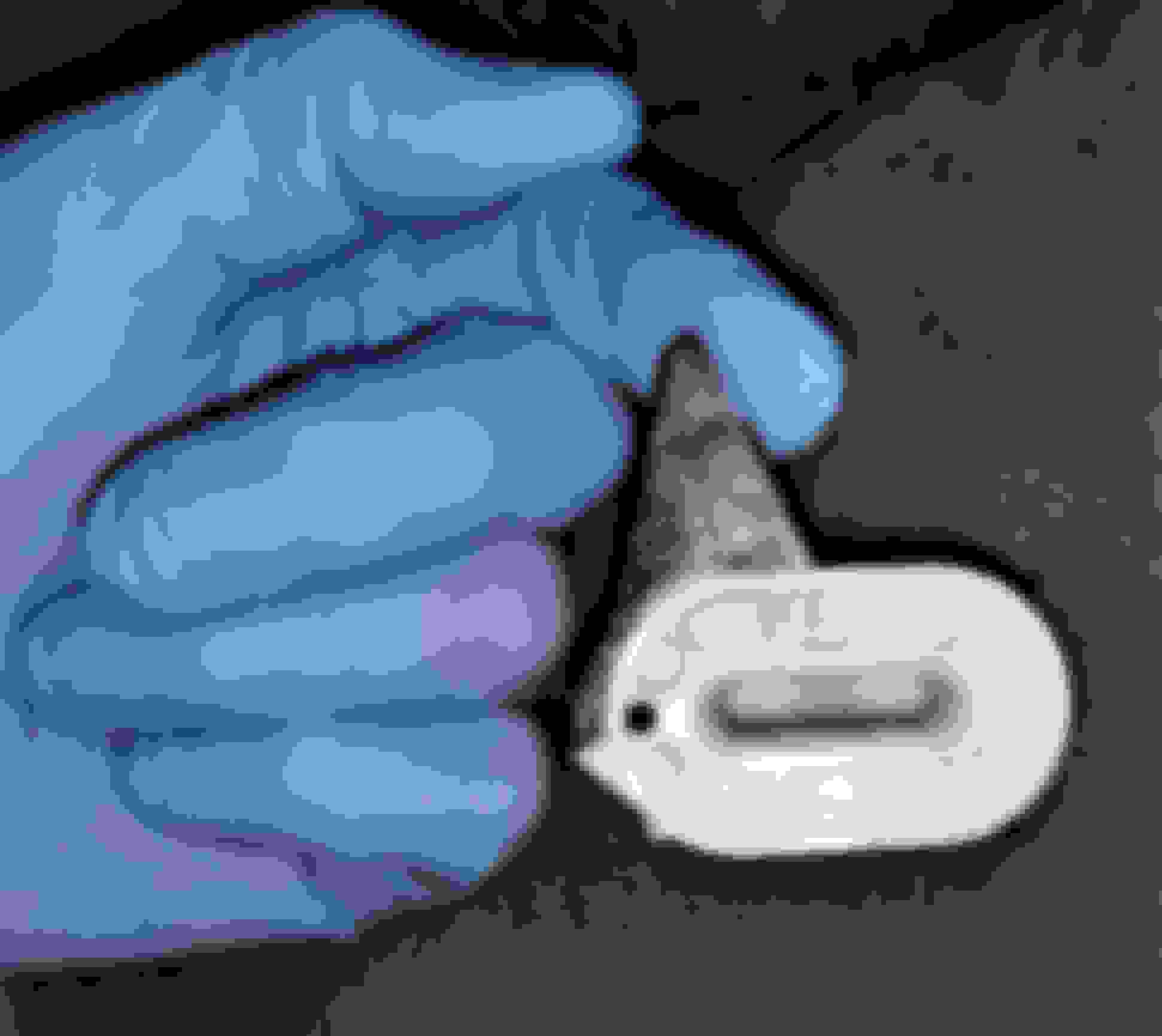
When the lever on the latch is pushed toward the left side of the car, the tab retracts and releases the U-shaped loop:
Some seat cushions are so flexible that once you release the latches on one side, the cushion will remain released so you can then work on the other side. But some cushions are stiff, and if you unlatch one side and then let go of the cushion, it will re-latch itself. If this happens, just release the latches again and slip the floormat up under the seat cushion to prevent it from re-latching. Then you can release the other side of the cushion.
Once you have all four latches disconnected, tilt the seat up and disconnect any electrical connectors you find, typically at the outer ends of the cushion:
Rear Seat Back Removal:
Prior to removing the seat back, lower the headrests all the way down. If your headrests are not motorized, there is a latch on one of the support rods on each headrest:
Push the latch button toward the rod to release the latch and push the headrest down:
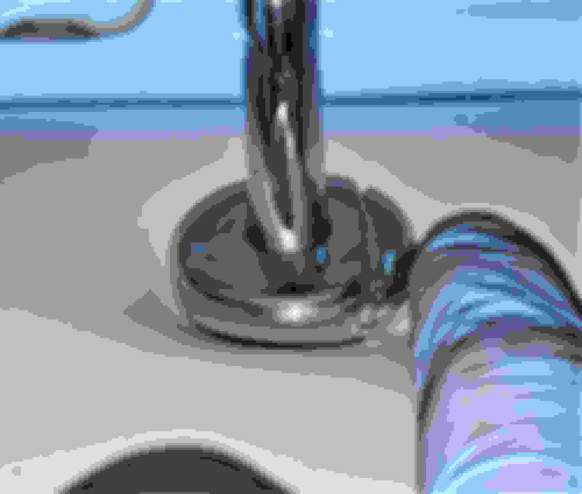
Next, the center seat belt must be disconnected at its lower end, where it is secured by an 18mm nut. Note how the center seat belt end and the buckle for the right passenger seat belt are oriented on the stud for reassembly:
Remove the nut, disconnect the seat belt and lay it up on the parcel shelf. Protect the parcel shelf from dust and dirt with a paper towel:
The seat back has four short studs along its lower edge that rest in U-shaped slots in brackets bolted to the body. Don't worry if your studs are rusted. They all seem to be. It must have something to do with the metallurgy of the studs. The upper end of the seat back is secured by two spring latches, one on either side, located directly below the headrests. Here is one of the four studs:
Here's a view of one of the bracket slots showing the white plastic liner:
Here's a view of a stud in its slot:
There are two webbed seat back release straps, one on each side. Theoretically, pulling on the straps releases the upper latches, and by simultaneously lifting and pulling the seat back, it should pull away from the body upright section and up and out of the slots on the lower bracket. Here's the left side strap:
More often than not, the latches do not want to release properly. Sometimes, you can persuade them to release by striking the seat back with the butt of your fist or palm of your hand just below the headrest:
The seat back is supported by, and latches to, two triangular support-hooks, one on each side below the headrests. The support-hooks have black plastic covers:
Each side of the seat back has a latch with a spring-loaded rod connected to the webbed strap. Below is a latch in its latched or at-rest position. The top of the rectangular opening in the latch frame rests on the top of the triangular support-hook. The spring-loaded rod fits into the slot on the underside of the support-hook:
When the webbed release strap is pulled, the spring-loaded rod is pulled down, releasing the seat back from the support-hook:
Often, one or both latches just does not want to release. Sometimes you must climb into the car facing the seat back and straddle the driveshaft tunnel so you can pull both straps simultaneously while also lifting the seat back up out of the slots and pulling it toward you off of the upper hooks. Sometimes repeatedly pulling and releasing the straps will help work the spring-loaded latch rods free of the support-hooks. Sometimes you also need to strike the top of the seat back with your hand as well.
If you just can't get the seat back to release, don't lose hope. Try removing the lower brackets. In addition to the one nut you have already removed for the center seat belt, there is another 18mm nut on the other side of the tunnel, plus two 13 mm nuts towards each outer end of the seat back, usually hidden by the lower edge of the leather:
To avoid staining the leather and fabric, clean your 13 mm deep socket and a short extension. This will help keep your dirty ratchet or impact tool away from the leather:
With the brackets disconnected, you should be able to work the seat back off while pulling the straps and lifting/pulling the seat back. Repeat all the above techniques and you'll get it.
You do not have to remove the seat back from the vehicle - you can just lean it forward while you install the Electronic Bypass Module:
When reinstalling the seat back, before pressing it into the upper latches, ensure that the seat belts are positioned on the front of the seat back and that the electrical connectors are not trapped behind the seat back:
Electronic Bypass Module (EBM) Installation:
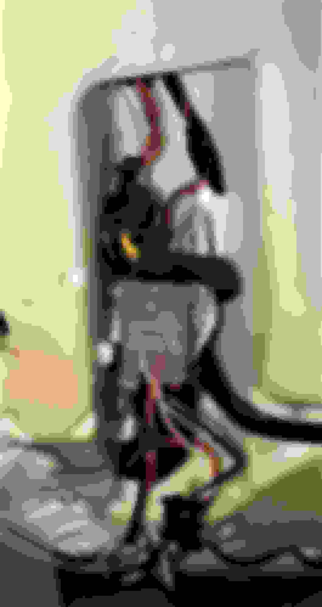
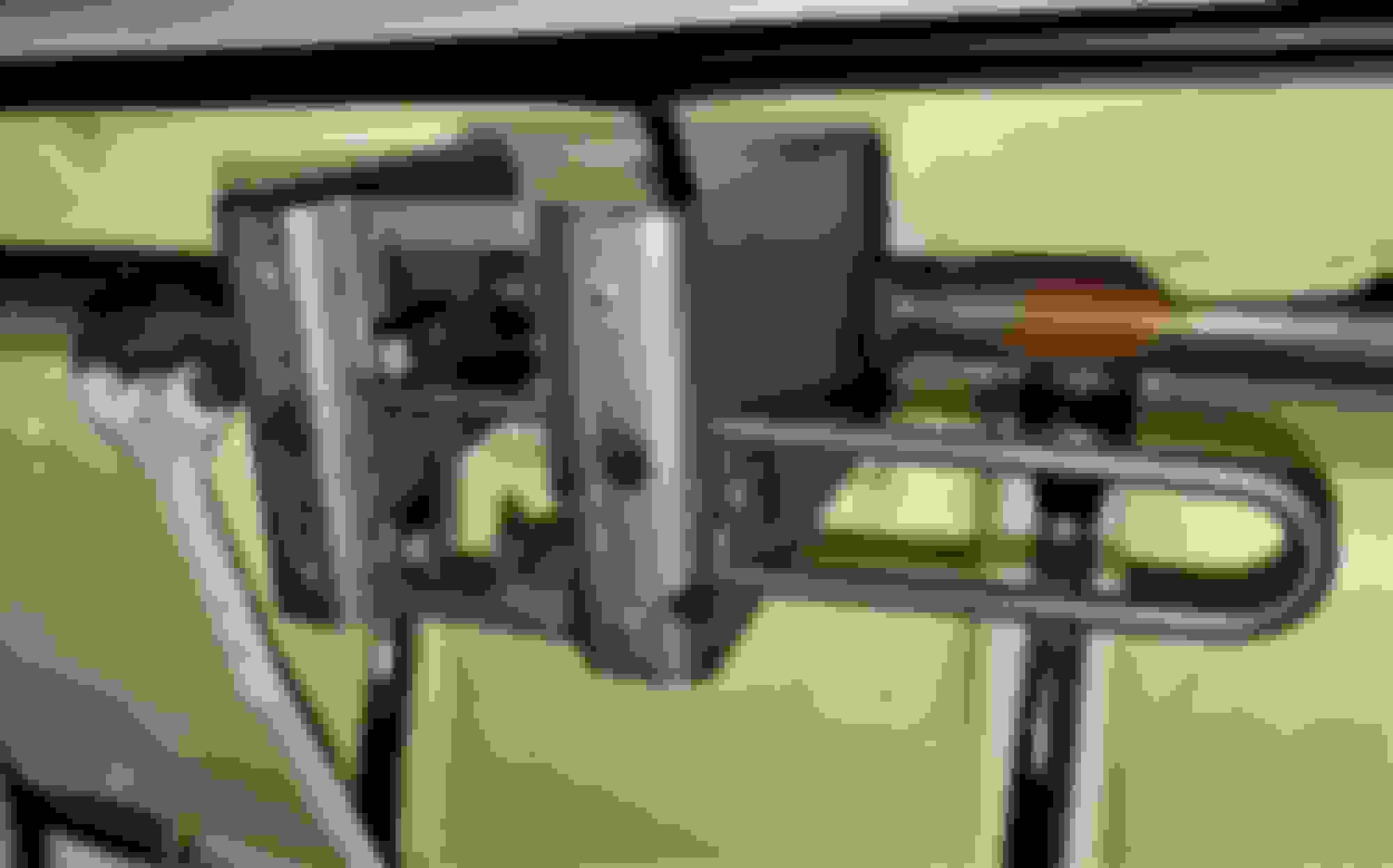
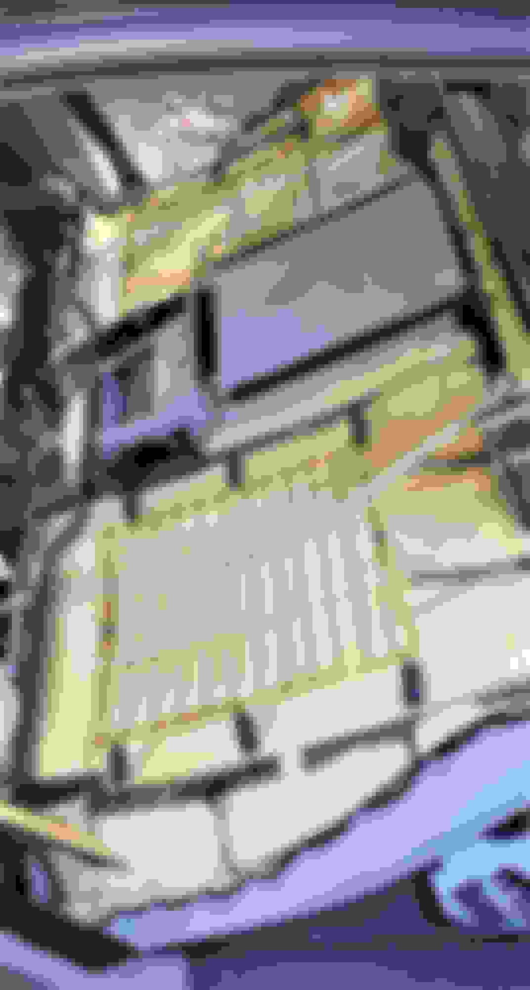
When the air suspension components are removed, various diagnostic trouble codes will be triggered in several modules. However, Arnott and Suncore offer dedicated electronic modules to fool the vehicle's computer systems so no irritating air suspension fault warnings are displayed in the Instrument Cluster. Arnott calls their unit the Electronic Bypass Module or EBM. It is installed by splicing into the Air Suspension Control Module (ASM) wiring. The ASM is located behind the rear seat back on the right hand side, behind a sound insulation pad:
The pad configuration is slightly different depending on model year, but on this early car just one fir tree fastener secured the upper edge of the pad:
With the pad folded down, the ASM is accessible:
Follow the Arnott or Suncore instructions for connecting the EBM, then secure the module and the loose connectors with zip ties:
Impressions of the Latest Arnott Kit:
I am pleasantly surprised by the ride and handling provided by the new Eibach spring/shock units in the Arnott kits. In the past, I have noted increased body roll when cornering with the coil kits, compared to the original air suspension (when working properly.) My first impression is that these Eibach units have noticeably less body roll. The ride is supple and controlled with excellent handling and less body roll while cornering. While I still prefer a properly-working air suspension with healthy Bilsteins and compressor, I think 99% of owners would be very happy with this latest iteration of the Arnott coil conversion kit.
 07-10-2022, 09:53 PM