Front Air Strut Cut-Away
#21
 05-27-2015, 04:06 PM


If you remove the plugs it goes to firm.
Its a trick used on track days to lock the shocks in Firm mode
Im not sure if there is a difference in the shocks used on the comfort vs sport unit though. Id guess the rates are harder in the sport ones to ho along with the higher rates on the airbags but don't know
Cheers
34by151
Its a trick used on track days to lock the shocks in Firm mode
Im not sure if there is a difference in the shocks used on the comfort vs sport unit though. Id guess the rates are harder in the sport ones to ho along with the higher rates on the airbags but don't know
Cheers
34by151
#22
05-27-2015, 05:21 PM


Join Date: Feb 2014
Location: Crossroads of America
Posts: 19,499
Received 12,932 Likes
on
6,463 Posts
http://www.google.com/url?sa=t&rct=j...93990622,d.b2w
Wabco refers only to "active dampers," so we're not given any clue as to whether the system is designed for shocks that use magnetorheological fluid or other technology, but your thought that they may just be electronically valved would make sense.
Cheers,
Don
Last edited by Don B; 08-09-2017 at 08:51 PM.

#24
05-27-2015, 07:59 PM

Veteran Member
#25
05-27-2015, 08:40 PM
Join Date: Feb 2014
Location: Crossroads of America
Posts: 19,499
Received 12,932 Likes
on
6,463 Posts
u102768,
Thanks for chiming in! That excerpt from the training manual is perfectly relevant and seems to confirm that the dampers have electrically- or electronically-controlled valves, rather than using magnetorheological fluid.
Looking at the diagram in your link, there is a "pump rod" labeled near the bottom end of the damper (rightward in the diagram), and a pump chamber higher up (leftward in the diagram). There appears to be an even narrower rod that passes down the center of the pump rod. Is it possible that it is this narrow rod that is controlled by the CATS solenoid at the top of the damper shaft, which opens and closes the Control Orifice to control the flow of fluid and thereby adjust the damping rate?
What do you think?
Coupled with reyesl's dissection photos, I think this may be the closest we've ever been to understanding the operation of this suspension!
Cheers,
Don
Last edited by Don B; 05-27-2015 at 08:52 PM.
#26
05-27-2015, 09:57 PM
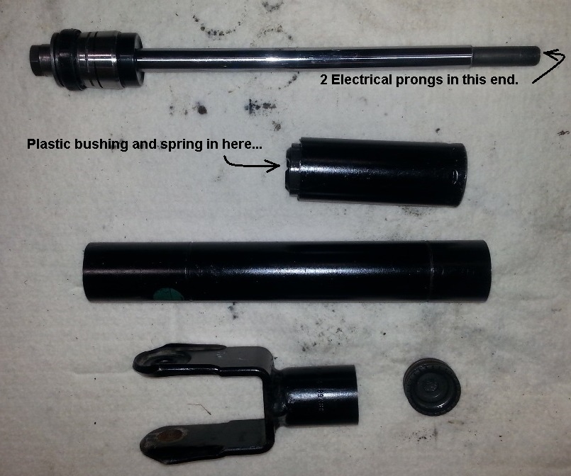
After surviving the explosive dissection of the strut and studying the document that u102768 posted, I might have an idea of how the fluid is controlled.
The strut had a combination of gas and fluid, gas in the lower section and fluid in the upper section. As the outer metal tube was cut, the fluid sprayed out as was expected, I was prepared and had the band saw covered. As the blade made its way to the other side, the gas propelled the shaft and innards about 50 ft out of my shop and I was holding the metal tube.....I was not prepared for that! Sounded like a rifle!

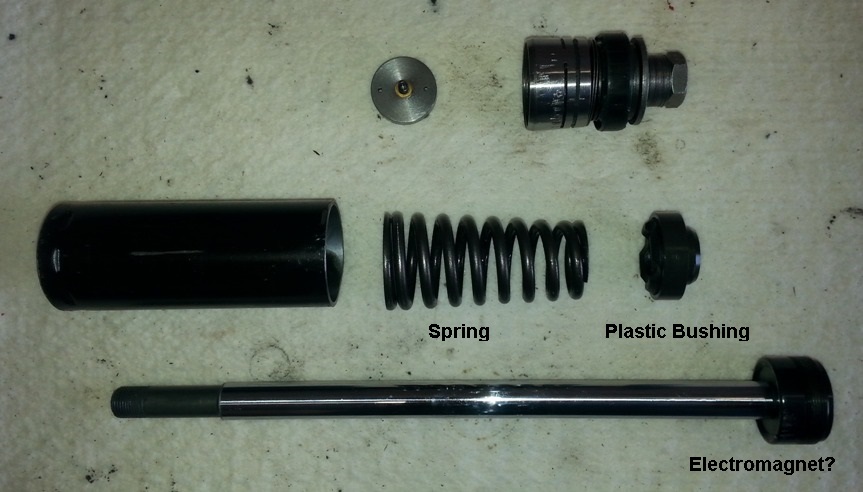
The lower section filled with gas might be an accumulator, not sure on that as there were no bladder material present. There is a valve screwed onto the electromagnet with a disc that moves, the disc is what most likely controls the flow of fluid. When voltage is applied, the disc is drawn toward the electromagnet and thus uncovers 2 ports. The disc is pushed back by a spring, covering the ports in the absence of voltage. No voltage, the strut is in the default or hard mode.


The strut had a combination of gas and fluid, gas in the lower section and fluid in the upper section. As the outer metal tube was cut, the fluid sprayed out as was expected, I was prepared and had the band saw covered. As the blade made its way to the other side, the gas propelled the shaft and innards about 50 ft out of my shop and I was holding the metal tube.....I was not prepared for that! Sounded like a rifle!
The lower section filled with gas might be an accumulator, not sure on that as there were no bladder material present. There is a valve screwed onto the electromagnet with a disc that moves, the disc is what most likely controls the flow of fluid. When voltage is applied, the disc is drawn toward the electromagnet and thus uncovers 2 ports. The disc is pushed back by a spring, covering the ports in the absence of voltage. No voltage, the strut is in the default or hard mode.


Last edited by reyesl; 05-27-2015 at 10:34 PM. Reason: Add Photos
#27
05-27-2015, 10:35 PM
Join Date: Feb 2014
Location: Crossroads of America
Posts: 19,499
Received 12,932 Likes
on
6,463 Posts
Wow, we're very happy you were not standing in the path of the spear when it fired!
Could the diaphragm material be thin metal?
I think you've done it, reyesl! You've explained how CATS works! If I'm not mistaken, your actual shock does not conform exactly to the diagram in u102768's document. I'm not surprised, since the actual shocks also do not conform to the cutaway view of the air spring/damper in the '04 New Model Introduction Dealer Training manual that I have.
Thanks for all your hard (and dangerous) work on this!
Cheers,
Don
The lower section filled with gas might be an accumulator, not sure on that as there were no bladder material present.
There is a valve screwed onto the electromagnet with a disc that moves, the disc is what most likely controls the flow of fluid. When voltage is applied, the disc is drawn toward the electromagnet and thus uncovers 2 ports. The disc is pushed back by a spring, covering the ports in the absence of voltage. No voltage, the strut is in the default or hard mode.
Thanks for all your hard (and dangerous) work on this!
Cheers,
Don
Last edited by Don B; 05-27-2015 at 10:40 PM.
The following users liked this post:
EssOess (09-15-2015)
#28
05-28-2015, 06:43 AM
Veteran Member
I think you've done it, reyesl! You've explained how CATS works! If I'm not mistaken, your actual shock does not conform exactly to the diagram in u102768's document. I'm not surprised, since the actual shocks also do not conform to the cutaway view of the air spring/damper in the '04 New Model Introduction Dealer Training manual that I have.
Thanks for all your hard (and dangerous) work on this!
Cheers,
Don
Thanks for all your hard (and dangerous) work on this!
Cheers,
Don
This also may explain why owners who abandon the CATS shocks for passive see only a marginal difference... on the Cadillac with the MagneRide if you lost that system (with fully variable shock control) it was readily apparent.
#30
05-28-2015, 10:45 AM
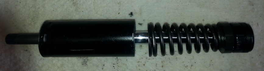
I clamped the rod on the band saw, turned it on and nothing! Just a light scratch, I forgot that the rod is normally made of hardened steel! Oh well, I got it with the chop saw.
The brass electrical prongs go through the rod into the “Electromagnet” where a “Copper Wire Coil” is energized, thus controlling the movement of the disk which in turn varies the flow rate of the fluid. I am wondering if the gas acts as a damper, hmmmmm?
We need a little input from the fellows at Bilstein, Jaguar, Arnott, and Strutmasters!
Last edited by reyesl; 05-28-2015 at 11:47 PM.
The following users liked this post:
EssOess (09-15-2015)
#31
05-28-2015, 02:50 PM
Veteran Member
Arnott replace the spring. similar to replacing a broken coil spring on a McPherson Strut unit. Clearly the unit is examined before the new air spring bladder is put on. Any leaking unit is scrap, obviously. I would think the shock electrical contacts are tested for continuity too. Bilstein are a quality manufacturer, not a Joe Noname operation. I have a set of Bilstein monotube shocks on my MG TF.
#32
05-29-2015, 07:00 AM
Veteran Member
The following users liked this post:
Don B (05-29-2015)
#33
05-29-2015, 12:50 PM
#34
05-29-2015, 03:30 PM
#35
05-30-2015, 04:17 PM
Veteran Member
#36
05-30-2015, 05:58 PM
More photos:
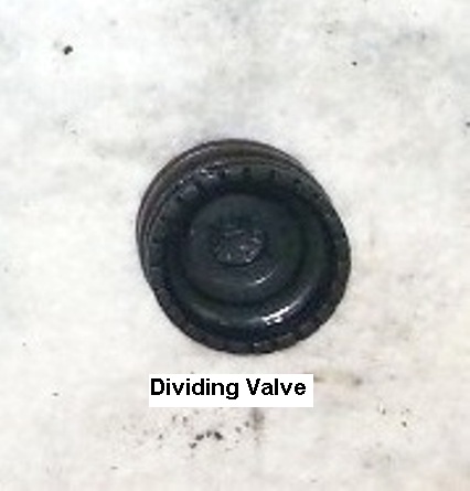
The Dividing Valve separates the Oil and Gas (usually nitrogen), the gas keeps the oil under permanent pressure which prevents foaming/cavitation. The seal appears to be rubber.

The Anti Cavitation Valve, along with the washer combinations, prevent any further cavitation/foaming. The seal appears to be made out of Teflon, similar to the compressor seal.

I believe Bilstein developed the gas pressurized shock for the Mercedes back in the late 50s. I would like to see a cut-away illustration of this strut assembly from Bilstein........
The Dividing Valve separates the Oil and Gas (usually nitrogen), the gas keeps the oil under permanent pressure which prevents foaming/cavitation. The seal appears to be rubber.
The Anti Cavitation Valve, along with the washer combinations, prevent any further cavitation/foaming. The seal appears to be made out of Teflon, similar to the compressor seal.
I believe Bilstein developed the gas pressurized shock for the Mercedes back in the late 50s. I would like to see a cut-away illustration of this strut assembly from Bilstein........
Last edited by reyesl; 05-30-2015 at 06:22 PM.
#37
09-15-2015, 07:30 AM

Thanks for all the great info. Any way to get some oil on the leaking bushing at the top to cause it to swell? Maybe trans stop leak oil possibly. Anyway I have an Arnott rebuilt front leaking after a 2-3 years. (bought the car recently, 125k mi 2004). Weather warm but just started leaking out of the top center hole. Don't have it off yet.
Last edited by rcannon; 09-15-2015 at 07:38 AM.

#39
11-06-2017, 11:09 AM

Senior Member
Reyes! Thanks for all of your work to exposed the air shock components, but looking forward to the companies for input is like snow in the mid Summer, they don't want us to know the secrets, some one might find out the way to fix it themselves, they want you to go buy their parts from the dealers.
Do you think pump the green goo-is stuff like the tire seal in the air hose connector to (not cured) slow down the leak, until the new units is replace? Just a thought. Thanks for all your work and pictures again.
Do you think pump the green goo-is stuff like the tire seal in the air hose connector to (not cured) slow down the leak, until the new units is replace? Just a thought. Thanks for all your work and pictures again.
