Heated Windshield
#21
As I mentioned in post #12 above, I have the two relays (R3 and R13) and the two fuses (F7 and F32) and I have resistance of approximately 1.8 ohms to ground from each fuse.
At some point I will remove my control unit and examine the circuit board behind the defrost switch. If anyone has a photo of the push button circuit board, that would be interesting. I wonder if SDD is needed to enable the feature, as the factory may have just changed the switch to disable the heated windscreen option.
The other way to enable it would be to fit a separate switch to put a ground onto pin 10 of connector EC41 (red/white)
The only reason I know the heated screen is fitted, is that one day the sun at a particular angle highlighted it in my garage.
Pete M
The following users liked this post:
Jaroslav Záruba (11-23-2023)
#22
Thanks, Thomas.
I checked my front fuse box today, and I have fuses 7 and 32, that control the heated windscreen (left and right) and heated wiper area. I also checked the output side of the fuses for resistance to ground. I have 1.6 and 1.8 ohms, which would equate to about 75 watts of power each. I don't think the screen is heated in response to the DEF button, as it doesn't clear quickly, but only in response to warm air from the aircon. I wonder if I inserted a switch to ground on the control wire to the fuse box that I could get a working heated screen. Looking forward to seeing how your reserve unit is wired.
Regards
Pete M
apologies for the delay, but because of work issues I was only able to come to the matter today. So I took my spare unit, which by the way comes from a X358 because I wanted the radio with the "Band" button to be able to upgrade to DAB+, and started to dismantle it.
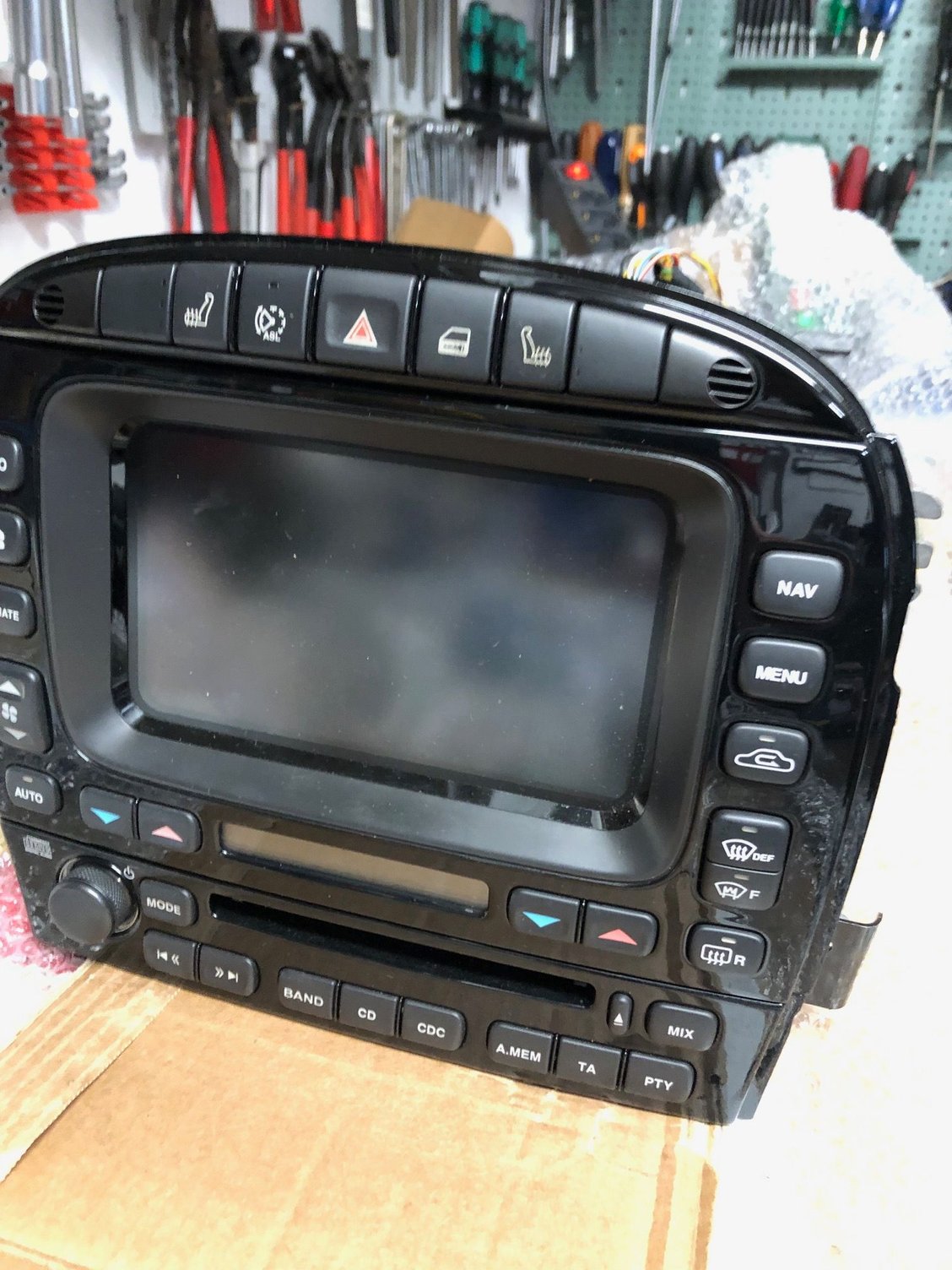
After removing the radio part and the buttons on top for the heated seats, etc., you can remove the front panel by removing 2 screws on each side of the unit plus two on top that (I did not take pictures of them), and unclipping the front panel on both sides:
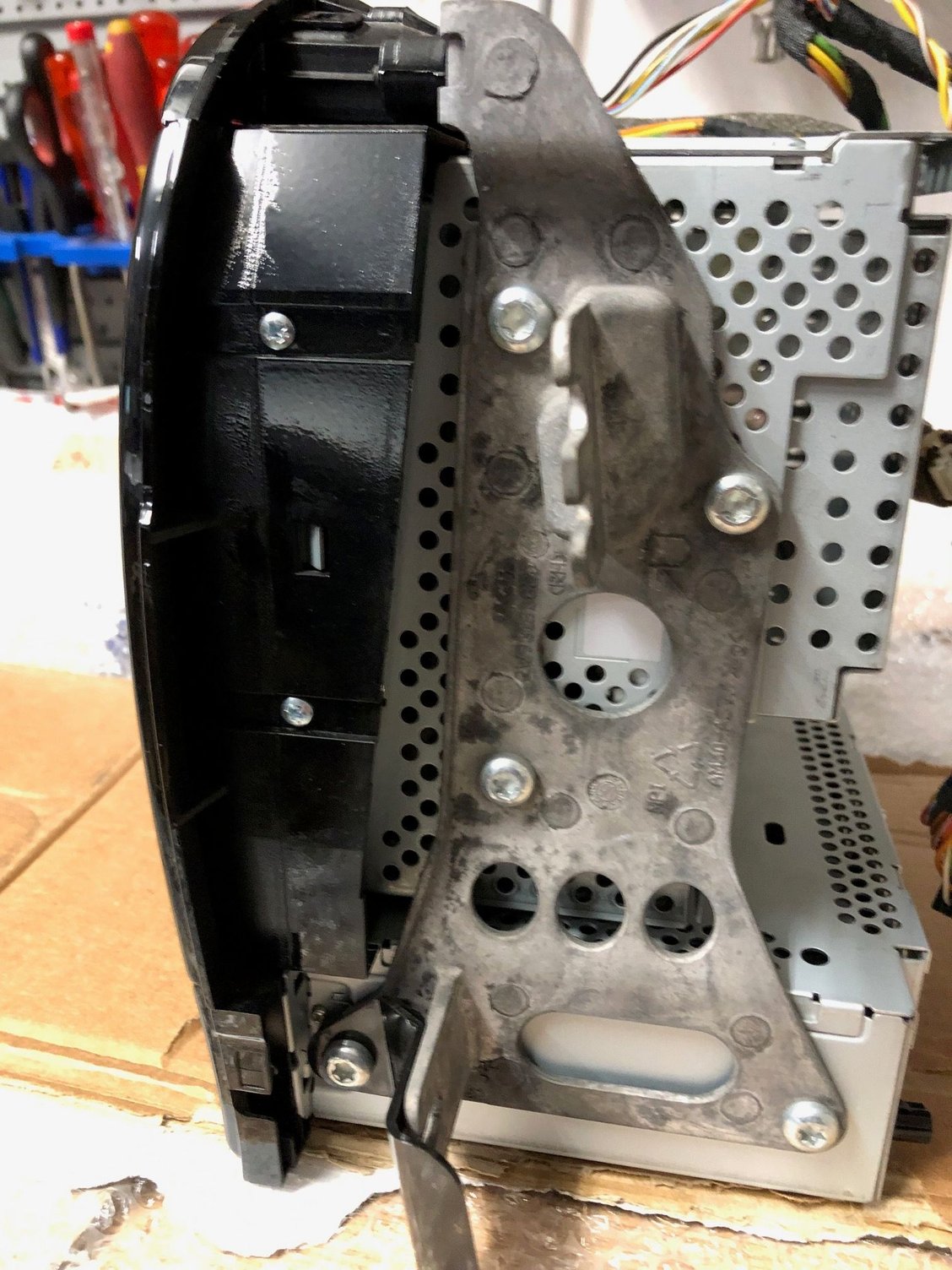
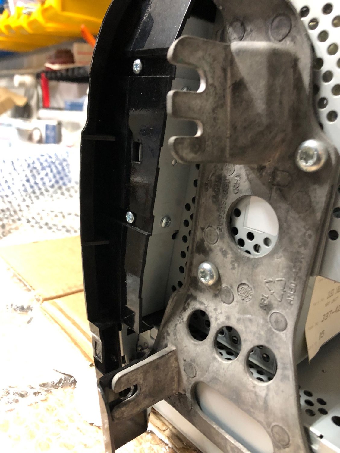
After removing the panel, it looks like this:
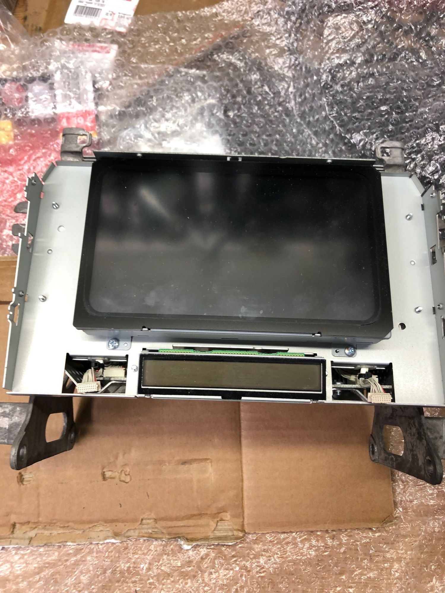

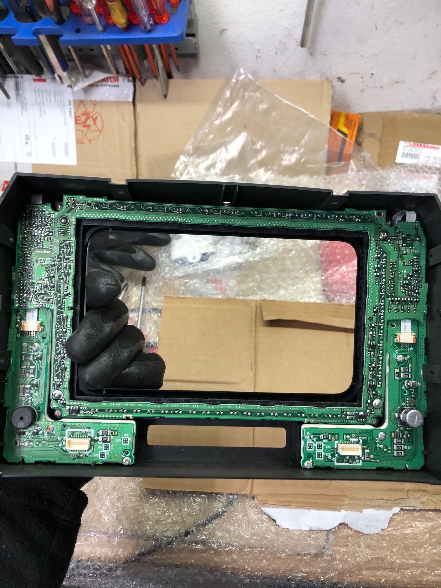
And this, unfortunately, is as far as I got. As you can see, the two smaller printed circuits disappear below the bigger one that frames the monitor, and I was not able to remove this bigger one as could not figure out how it is fixed. There are some small screws that you can see, but Ii was not sure whether they keep this board fixed.
In any case, the buttons for the heated front and rear screens go directly to the printed circuit on the bottom left, so that you have at least to replace the circuit if you want to have the additional buttons.
Sorry that I could not go further, but I hope that this helps a bit, nonetheless.
Best regards,
Thomas
#23
Hi Pete,
apologies for the delay, but because of work issues I was only able to come to the matter today. So I took my spare unit, which by the way comes from a X358 because I wanted the radio with the "Band" button to be able to upgrade to DAB+, and started to dismantle it.
--snip photos---
And this, unfortunately, is as far as I got. As you can see, the two smaller printed circuits disappear below the bigger one that frames the monitor, and I was not able to remove this bigger one as could not figure out how it is fixed. There are some small screws that you can see, but Ii was not sure whether they keep this board fixed.
In any case, the buttons for the heated front and rear screens go directly to the printed circuit on the bottom left, so that you have at least to replace the circuit if you want to have the additional buttons.
Sorry that I could not go further, but I hope that this helps a bit, nonetheless.
Best regards,
Thomas
Thank you so much for your investigation. That's exactly what I wanted to see. I will examine your photos closely, especially the last one. I appreciate you showing the process of disassembly, too, as that's not always obvious.
Kind regards
Pete M
#24
Hi Pete,
you're welcome. If the last picture is not enough to seen the details, I can take some more. The disassembly process is not too onerous, the only minor pain are the two connectors that can be seen at the bottom in picture #4. They need to be plugged into the white connectors at the bottom in the last picture.
Best regards,
Thomas
Thread
Thread Starter
Forum
Replies
Last Post
Currently Active Users Viewing This Thread: 1 (0 members and 1 guests)


