Jag Wouldn't Start
#23
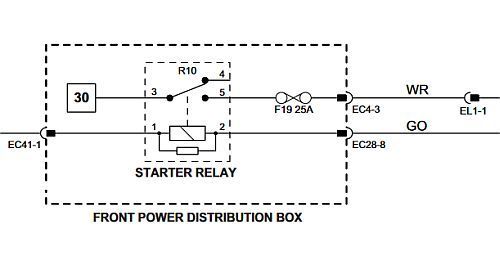
See Electrical Guide, Fig. 02.2 for starter motor circuit details. Starter relay is in Front Power Distribution Box.
ECM controls circuit through pin PI1-041 STARTER RELAY DRIVE: TO ACTIVATE, ECM SWITCHES CIRCUIT TO GROUND
If you have all the manuals, have you performed any pin tests to determine if you have complete circuits?
ECM controls circuit through pin PI1-041 STARTER RELAY DRIVE: TO ACTIVATE, ECM SWITCHES CIRCUIT TO GROUND
If you have all the manuals, have you performed any pin tests to determine if you have complete circuits?
#24
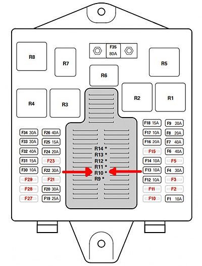
You see, that is my problem. There are no relays markings in image of fuse box
pointing to that relay and schematic diagram point to something only some
car electrician would understand and I'm not one of them. If you have picture
of fuse box with arrow pointing to relay, please post it to help me and hundreds
of people who will be eventually visiting this forum.

Last edited by jagxjr; 02-21-2024 at 01:55 PM.
#25
#26
#28
Those relays with an asterisk * beside them are referred to as system replays.
That simply means they are incorporated in the power distribution fuse box circuit board construction - soldered in and not readily user replaceable unlike their socket counterparts that you can simply pull out and replace as needed.
System relays can be replaced if the fuse box is removed and then fully dismantled, but you need some soldering skills and set aside a couple of hours to do that job.
A Dremel with a fine cutting metal blade to cut the 100+ links that join the front and rear PCBs together is very helpful to separate the PCBs to get to the faulty relay's soldered connections, then it is just a case of bridging across the links you cut to put the two PCBs of the power distribution box back together again.
The following users liked this post:
NBCat (02-22-2024)
#29
You can check the output of that relay if you check for voltage at starter relay activation input on starter motor. Will show whether the system wiring to that point works or if it is the starter relay activation relay in the box. Then check the input to the relay from the ECM. It should turn on if the ignition is turned on and there security checks were verified. Either test can be done first.
Last edited by OldKarz; 02-26-2024 at 08:37 AM.
Thread
Thread Starter
Forum
Replies
Last Post
Currently Active Users Viewing This Thread: 1 (0 members and 1 guests)


