Transmission fault correction procedure corroboration needed. Have SDD
#42
Ohms:
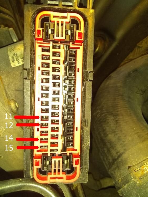
1. pins 12 & 14; 118.7 ohms
2. pins 11 & 15; 121.0 ohms
I will look for and disconnect the tcm connector by the bell housing and re test 12 &14 next...
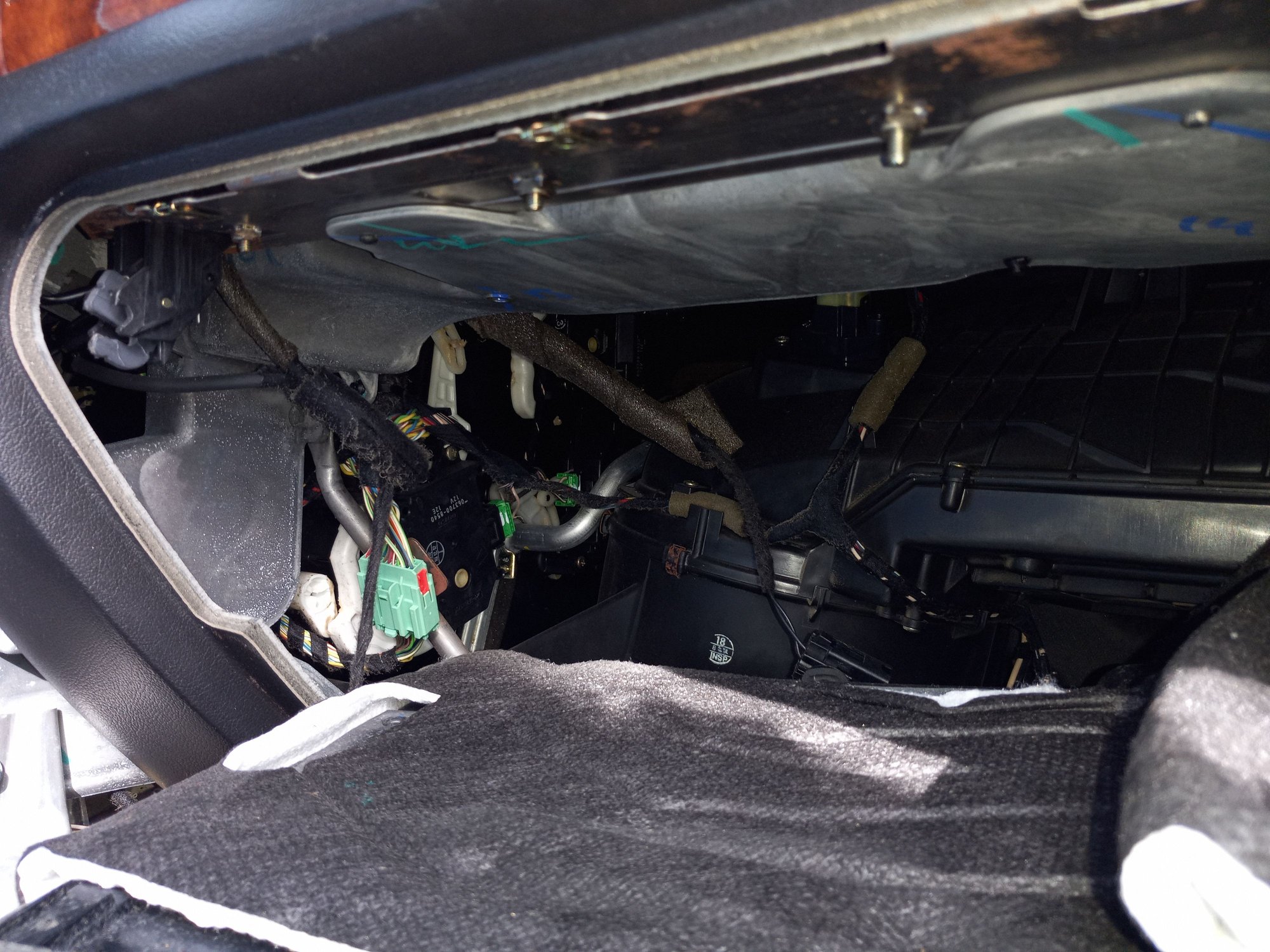
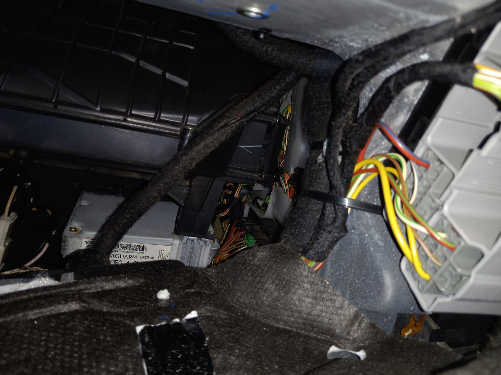
Please advise if know how to disconnnect the TCM for the next test. I am able to see the circular connector on the right rear of gear box, and can see the harness moving forward and above the gearbox but havent found a connector yet. On top rear of engine behind the intake close to the firewall theire are harnesses comming together and bolted to engine, but haven't seen a connector yet. Please advise.
Last edited by BReyes; 09-15-2021 at 09:11 AM. Reason: Looking for TCm connector
#43
Since your values are good, to show the buss is complete, the TCM disconnect will not help until the next procedure for bus shorts to ground and B+. The Workshop Manual has a very detailed procedure for doing this. Since you are having TCM comm losses I would concentrate on the CAN pins on the connector you are using now. If nothing amiss is found you may have to check the mating pins on the module itself since it has been removed from the circuit by disconnecting the connector. -ve and positive should be greater than 10k ohms to ground with the battery disconnected and key on. If you get less than 10k, on the CAN buss to the TCM, disconnect it and test again. The connector is right on the transmission and is a quarter turn to remove if I remember correctly. If there is oil in the connector you have most likely found your problem.
The Workshop manual is available on this site if you do not have it already
The Workshop manual is available on this site if you do not have it already
#44
Since your values are good, to show the buss is complete, the TCM disconnect will not help until the next procedure for bus shorts to ground and B+. The Workshop Manual has a very detailed procedure for doing this. Since you are having TCM comm losses I would concentrate on the CAN pins on the connector you are using now. If nothing amiss is found you may have to check the mating pins on the module itself since it has been removed from the circuit by disconnecting the connector. -ve and positive should be greater than 10k ohms to ground with the battery disconnected and key on. If you get less than 10k, on the CAN buss to the TCM, disconnect it and test again. The connector is right on the transmission and is a quarter turn to remove if I remember correctly. If there is oil in the connector you have most likely found your problem.
The Workshop manual is available on this site if you do not have it already
The Workshop manual is available on this site if you do not have it already
Forum members,
Where is the above mentioned 2004 XJ Manual?
Where may I find the above mentioned diagnostic procedure?
The manuals I have so far are:
2004 XJ 8 Electrical guide jpg, and I keep looking for the above referenced diagnostic procedure but haven't found it yet. Is it in this manual?
2004- 2009 XJ 8 Manual jpg (over 7000 pages) and the page headings are mostly reading 2005 XJ, and I keep looking for the above referenced diagnostic procedure. Is it in this manual?
2004-2009 Jaguar XJ 8 Manual jpg.
#45
#47
It should be in your Workshop manual - The one I have is only 6361 pages probably due to formatting - you should look beginning at PINPOINT TEST G239843p1. In mine it starts on page 5321 but will be further along in yours. use the search function for the test number. However concentrate on ICM, TCM and ECM tests. If you disconnect ECM and ABS connector you can use the ABS output pins, previously suggested, to test the values for the TCM without much of the manual process. Check for grounds and B+.
The following users liked this post:
BReyes (11-02-2021)
#48
2 issues to mention;
Oilstainís comment didnít mention WHY as it happened to me. One morning the car wouldnít start. There WAS power; I had an issue a few months back where my battery drained and it was recharged but shortly drained again to the point where even with a jump; there wasnít enough power to start the car and get it in gear! That issue was simply replacing the battery. of course I also had to replace the alternator because that is why the battery died.
So I was afraid the same thing was happening and I took the time to take out my battery take it to Napa let them charge it although it took them all day and it didnít charge that much. When I took it back I still couldnít get things to work so at that point I had to call a tow truck it was dark by the time it came. I realized the shifter cable had slipped because the reason why it wasnít starting was because park was no longer park, Using the stupid breakable plastic release tab (Prior years this was made of metal!) I realized in the dark that reverse was actually neutral because thatís what light was lit up then I was able to start the car but unfortunately I didnít have enough room to put it in drive so I still had to have a tow but at least I knew what happenedóthe shifter cable slipped.
The other possibility but I donít think anyone has mentioned it was a TSB XJ413Ė02. this talks about three wire connecting blocks in the 2004 XJ8 had a couple pins in the wire connector block were made too short so they donít make a good connection. Even though my model year was later these were the exact symptoms I was having and before that was trying all sorts of things like connecting and reconnecting the battery removal in a solenoid and put it back in.
Of all the symptoms outlined in the TSB mention one more I remembered was the transmission shift lights went out. It can happen when the car is running but when you shut it off you canít start it again. Luckily I found out itís only the wiring block connected to the ABS unit in the front of the car on the passenger side and all I have to do is occasionally push down on the block to reseat the wires. According to images Iím seeing for used parts that wiring block thatís connected to the ABS/DSC unit is supposed to have some sort of plastic dust cover mine does not it looks like it was broken off and maybe thatís why itís more like thereís dirt in there rather than bad wiring. Roughly jarring the car can make it come loose again but luckily opening the hood & pressing the block to seat the wires typically takes care of if.
Unfortunately thereís also two other wire blocks not in the greatest of places. You mentioned different wiring blocks in this thread but I did not read the whole thing; itís too long and wiring to me is like web programmingóit bores me & my brain turns to mush and I get lost in the fog of it.
Last edited by mc690; 09-28-2021 at 12:12 PM. Reason: display glitch, couldnít edit
The following users liked this post:
BReyes (11-02-2021)
#49
2 issues to mention;
Oilstain’s comment didn’t mention WHY as it happened to me. One morning the car wouldn’t start. There WAS power; I had an issue a few months back where my battery drained and it was recharged but shortly drained again to the point where even with a jump; there wasn’t enough power to start the car and get it in gear! That issue was simply replacing the battery. of course I also had to replace the alternator because that is why the battery died.
So I was afraid the same thing was happening and I took the time to take out my battery take it to Napa let them charge it although it took them all day and it didn’t charge that much. When I took it back I still couldn’t get things to work so at that point I had to call a tow truck it was dark by the time it came. I realized the shifter cable had slipped because the reason why it wasn’t starting was because park was no longer park, Using the stupid breakable plastic release tab (Prior years this was made of metal!) I realized in the dark that reverse was actually neutral because that’s what light was lit up then I was able to start the car but unfortunately I didn’t have enough room to put it in drive so I still had to have a tow but at least I knew what happened—the shifter cable slipped.
The other possibility but I don’t think anyone has mentioned it was a TSB XJ413–02. this talks about three wire connecting blocks in the 2004 XJ8 had a couple pins in the wire connector block were made too short so they don’t make a good connection. Even though my model year was later these were the exact symptoms I was having and before that was trying all sorts of things like connecting and reconnecting the battery removal in a solenoid and put it back in.
Of all the symptoms outlined in the TSB mention one more I remembered was the transmission shift lights went out. It can happen when the car is running but when you shut it off you can’t start it again. Luckily I found out it’s only the wiring block connected to the ABS unit in the front of the car on the passenger side and all I have to do is occasionally push down on the block to reseat the wires. According to images I’m seeing for used parts that wiring block that’s connected to the ABS/DSC unit is supposed to have some sort of plastic dust cover mine does not it looks like it was broken off and maybe that’s why it’s more like there’s dirt in there rather than bad wiring. Roughly jarring the car can make it come loose again but luckily opening the hood & pressing the block to seat the wires typically takes care of if.
Unfortunately there’s also two other wire blocks not in the greatest of places. You mentioned different wiring blocks in this thread but I did not read the whole thing; it’s too long and wiring to me is like web programming—it bores me & my brain turns to mush and I get lost in the fog of it.
Thanks for your reply,
I have not found where the TSBs are located.
Forum members , please advise if you know where the TSBs are.
Thank you.
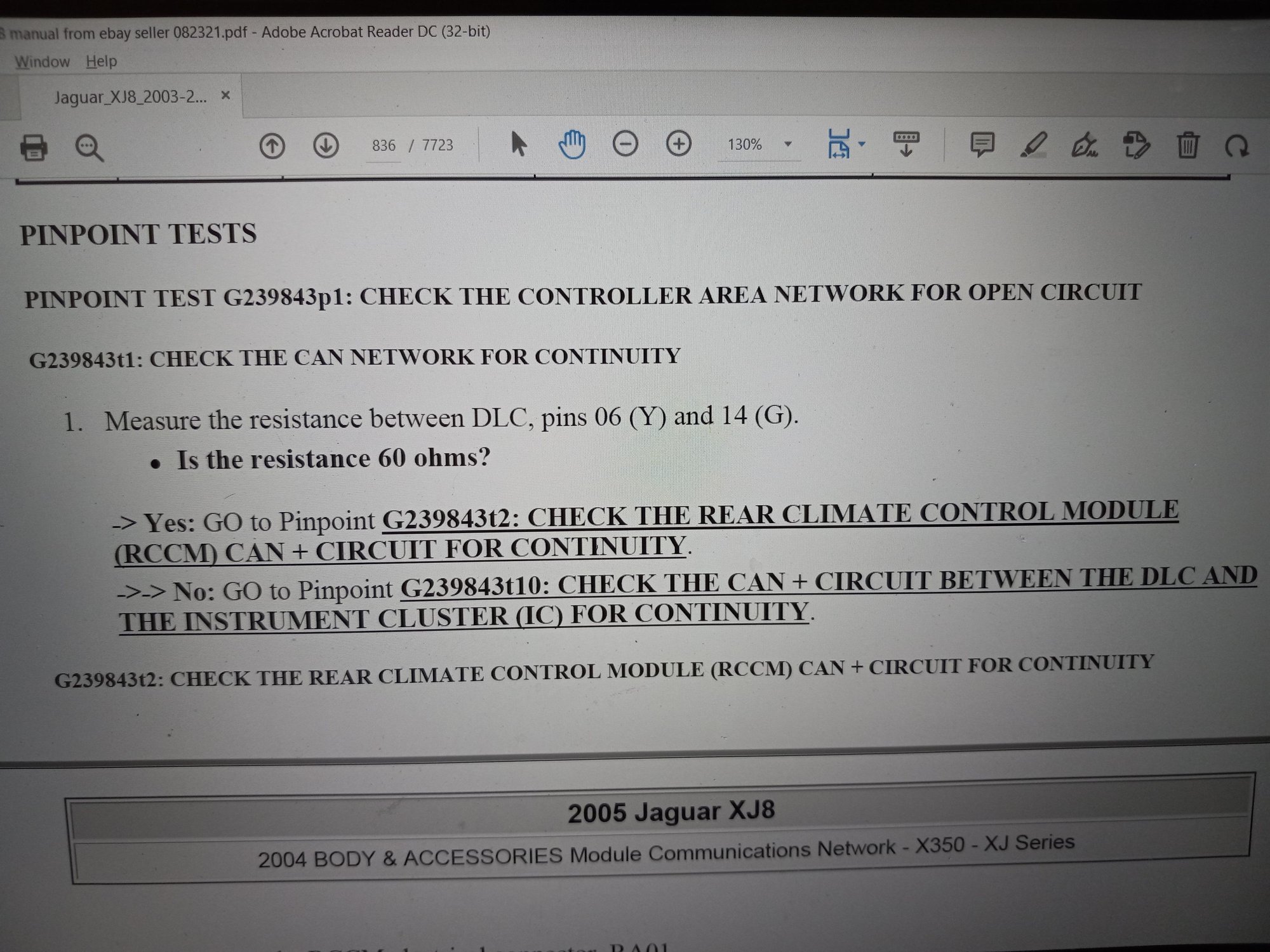
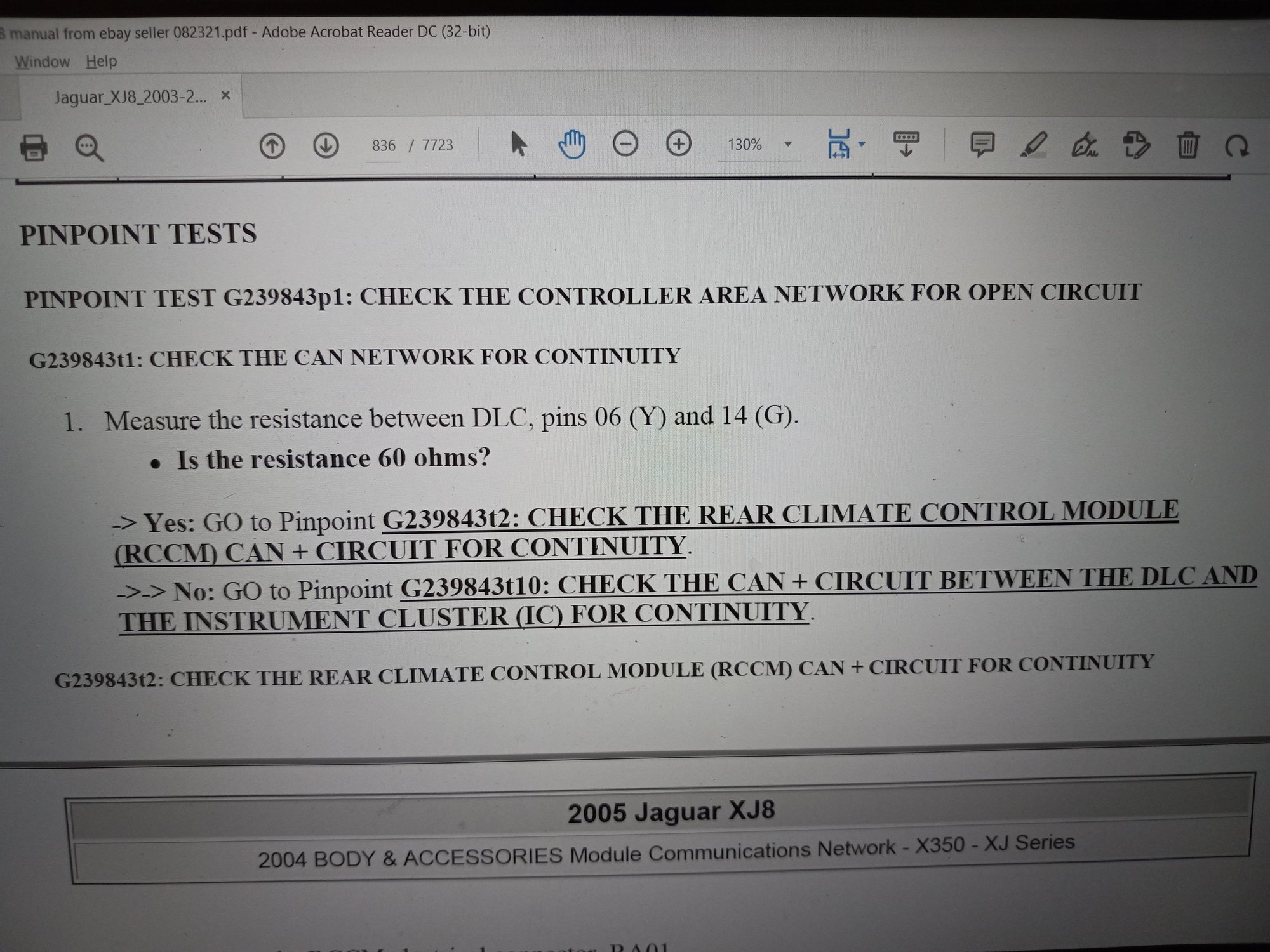
I am presently working on the PINPOINT TEST G239843p1.I have found the diagnostic procedure on my 2003-2008 manual on pg 836 (of 7723pgs). This test is for :Multiple CAN modules with CAN DTCs flagged, CAN circuit open circuit, short circuit to B+, short circuit to ground. CCM internal CAN fault.
Last edited by BReyes; 10-26-2021 at 11:08 AM. Reason: typographical correction
#50
The following users liked this post:
BReyes (11-02-2021)
#52
Since your values are good, to show the buss is complete, the TCM disconnect will not help until the next procedure for bus shorts to ground and B+. The Workshop Manual has a very detailed procedure for doing this. Since you are having TCM comm losses I would concentrate on the CAN pins on the connector you are using now. If nothing amiss is found you may have to check the mating pins on the module itself since it has been removed from the circuit by disconnecting the connector. -ve and positive should be greater than 10k ohms to ground with the battery disconnected and key on. If you get less than 10k, on the CAN buss to the TCM, disconnect it and test again. The connector is right on the transmission and is a quarter turn to remove if I remember correctly. If there is oil in the connector you have most likely found your problem.
The Workshop manual is available on this site if you do not have it already
The Workshop manual is available on this site if you do not have it already
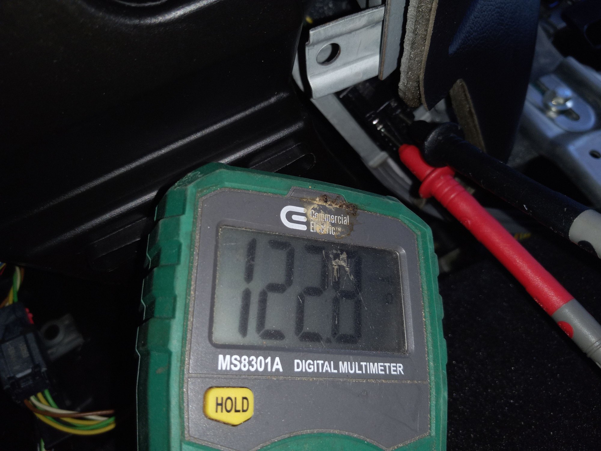
I have checked the first test. Result 128ohms.

#53
Are you sure every module is connected? You basically checked this value before when you did the tests I suggested at the ABS connector. At that time both termination resistors were seen. Check the ABS connector for corrosion. The signal does not seem to be passing in/out of the ABS unit.
The following users liked this post:
BReyes (11-02-2021)
#54
Are you sure every module is connected? You basically checked this value before when you did the tests I suggested at the ABS connector. At that time both termination resistors were seen. Check the ABS connector for corrosion. The signal does not seem to be passing in/out of the ABS unit.
Presently the rear climate control unit is disconnected and has been since I removed the center console (I have been wondering/thinking it being disconnected as being incorrect for further testing and diagnosis but wasnt sure if rear ac control remaining disconnected until reinstall console would be a problem), and the ABS connector is disconnected since I disconnected it to test pins (I have been wondering/thinking it being disconnected as being incorrect for further testing and diagnosis, but did not want to risk having to connect/disconnect it any more than once).
#55
Are you sure every module is connected? You basically checked this value before when you did the tests I suggested at the ABS connector. At that time both termination resistors were seen. Check the ABS connector for corrosion. The signal does not seem to be passing in/out of the ABS unit.
Thank you for noticing (ABS connector continuity/it still being disconnected from previous test) and commenting about it.
I retested test after reconnecting ABS connector (and Rear AC controller) G239843p1 resistance between DLC pin 6 and DLC pin 14: Result 60ohms as test says it should be. I will next proceed as manual states to proceed to test G239843t2.


#56
#57
#58
#60


