When you click on links to various merchants on this site and make a purchase, this can result in this site earning a commission. Affiliate programs and affiliations include, but are not limited to, the eBay Partner Network.
Back at it ...
Accessing the remaining modules and continuing the pinpoint tests.
This post is a summary of previous tests and results:Problem:
Stuck in Park issue: no PRND light:
P1638 indicates you have a CAN bus communication error. When the CAN bus is in error, the gear locking solenoid will not allow the shifter to be moved out of Park. Also, not having the 'P' light up indicates that the CAN is down. Do a search for P1638 on this forum. The info will guide you in checking your CAN connections.
Running a series of tests including pinpoint testsas set forth in manual beginning with g239843p1.
Pinpoint test in Manual G239843p1: Check the CAN for open circuit:
Test:
Measure resistance between DLC pin 6(Y) and DLC pin 14(G):
Is resistance 60 ohms?
If yes go to G239843t2: Check RCCM CAN+ for continuity.
If no go to G239843t10: Check the CAN+ circuit between the DLC and the IC for continuity.
Result: Yes. resistance is 59.3 ohms
Therefore yes, CAN has an open circuit, go to G239843t2: Check RCCM CAN+ for continuity.
Pinpoint test in Manual G239843t2: Check RCCM CAN+ for continuity.
Test:
Disconnect RCCM connector, RA01;
Measure resistance between DLC pin 6(Y) and RA01 pin 08(Y):
Is resistance greater than 5 ohms?
If yes, repair the high resistance circuit.
If no go to G239843t3: Check the RCCM CAN – for continuity.
Result: No, resistance between DLC pin 6(Y) and RA01 pin 08(Y): is 0 ohms: based on given that RCCM connector RA01(16 way connector) pins are not numbered, I am assuming RA01 16 way connector pin outs are:
Pin 1 is a pin on corner with red wire and 2 yellow tracers: G239843t3 result: continuity;
Pin 8 (Y) is a pin on corner with yellow wire and 2 red tracers G239843t3 result: 0 ohms;
Pin 9 is a pin on corner with blue wire and red tracer G239843t3 result: 0 ohms;
Pin 16 is a pin on corner with red wire: G239843t3 result: 60.7 ohms.
Therefore no, RCCM CAN + does not have continuity, go to G239843t3: Check the RCCM CAN – for continuity.
Note there is an assumption here that RCCM RA01 connector pin 8 is corner pin with yellow wire with 3 red tracers.
And manual I am using says RA01 pin 8 (Y)
Pinpoint test in Manual G239843t3: Check RCCM CAN- for continuity.
Test:
Disconnect RCCM connector, RA01
Measure the resistance between DLC pin 14 (G) and RA01 pin 16 (G):
Is resistance greater than 5 ohms?
If yes, repair the high resistance circuit.
If no, go to G239843t4: Check the Yaw Rate Sensor CAN- for continuity:
Result: No, resistance between DLC pin 14(G) and RA01 pin 16(G): is 0 ohms: based on given that RCCM connector RA01(16 way connector) pins are not numbered, I am assuming RA01 16 way connector pin outs are:
Pin 1 is a pin on corner with red wire and 2 yellow tracers: G239843t3 result: 59.4 ohms;
Pin 8 (Y) is a pin on corner with yellow wire and 2 red tracers G239843t3 result: 0 ohms;
Pin 9 is a pin on corner with blue wire and red tracer G239843t3 result: 0 ohms;
Pin 16 is a pin on corner with red wire: G239843t3 result: continuity.
Therefore no, RCCM CAN + does not have continuity, go to G239843t3: Check the RCCM CAN – for continuity.
Note there is an assumption here that RCCM RA01 connector pin 16 (G) is corner pin with red wire.
But manual I am using says RA01 pin 16 (G)
Pinpoint test in Manual G239843t4: Check the Yaw Rate Sensor CAN + circuit for continuity:
Test:
Disconnect the Yaw Rate Sensor connector IP23;
Measure resistance between DLC pin 6 (Y) and IP23 pin 02 (Y):
Is resistance greater than 5 ohms?
If yes, repair the high resistance circuit.
If no, go to G239843t5: Check the Yaw Rate Sensor Can- circuit for continuity.
Result: No, resistance is 0 ohms
Therefore no, RCCM CAN – does not have continuity.
Pinpoint test in Manual G239843t5: Check the Yaw Rate Sensor CAN- circuit for continuity:
Test:
Disconnect the Yaw Rate Sensor connector IP23;
Measure resistance between DLC pin 14 (G) and IP23 pin 01 (U):
Is resistance greater than 5 ohms?
If yes, repair the high resistance circuit.
If no, go to G239843t6: Check the ASCCM CAN+ circuit for continuity.
Result: No, resistance is 0 ohms
Therefore: Yaw Rate Sensor CAN- circuit does not have continuity
Asked to check, “OK. So you have a short to ground on the CAN bus! Disconnect your ABS connector and test for short to ground again. My bet is that you will no longer have a short at DLC.”
Test to check for short to ground with ABS connector and battery disconnected:
Disconnect your ABS connector and test for short to ground again.
Disconnect battery.
Measure resistance between DLC pin 6 and negative post of battery.
Result: 0 ohms.
Test to check for short to ground with ABS connector and battery disconnected:
Disconnect your ABS connector and test for short to ground again.
Disconnect battery.
Measure resistance between DLC pin 6 and negative post of battery
Result: 0 ohms.
Test to check for short to ground with j-gate connector and battery disconnected:
I disconnected the negative terminal at the battery;
I disconnected the j-gate connector.
Measure resistance between DLC pin 6 and ground.
Result: pin 6 to neg battery post: 0 ohms;
Test to check for short to ground with j-gate connector and battery disconnected:
I disconnected the negative terminal at the battery;
I disconnected the j-gate connector.
Measure resistance between DLC pin 14 to negative battery post: 0 ohms.
Result: DLC pin 14 to negative battery post: 0 ohms.
DLC test: test result: 12/07/21: I disconnected the negative terminal at the battery; I disconnected the j-gate connector (all other connectors I recall are connected ) I tested resistance:
1. DLC pin 6 to neg battery post: 0 ohms; 2. DLC pin 14 to negative battery post: 0 ohms.
That should narrow it down to the Instrument cluster, Air suspension module,Rear climate control module, DLC or wiring/connectors between them. Disconnect each one of these modules, one at a time, do not reconnect until the ground goes away and see where the short to ground disappears. If it does go away with a module check its connector pins between CAN+ and Ground and CAN- and Ground. Then we can go from there.
If possible corroborate with me on tests to further this diagnosis of problem.
I will next perform tests of CAN+ and CAN - , using above logic of testing DLC pin 6 to ground and testing DLC pin 14 to ground, once I disconnect he ABS module.
I will test (1) Test DLC pin 6 to ground, (2) Test DLC pin 14 to ground
Instead of continuing down each pinpoint test as there are a large number I am next testing Communication errors on CAN+ and checking CAN - with the Air Suspension module disconnected.
What connectors must be disconnected to disconnect the ABS module and run the CAN+ and CAN tests.
What pin points need to be tested?
Picture of the air suspension Module behind rear seat back on right side of vehicle:
You have already disconnected the ABS, ECU, TCM, ASCM, DSCM and CCM from the CAN Bus when you disconnected the J-Gate. At that point you checked CAN+ and CAN -VE to ground, at the DLC connector. You have a dead short in both cases, which will kill CAN Bus. Your short is somewhere in the ASM, ICM, ASM or affiliated wiring. With battery disconnected and ohm meter on DLC 4 and 14 disconnect the modules, and leave each disconnected, until the short goes away. If it does not then you will have to start chasing down a wire short. You have done some of that already. However I would do the module disconnect to make sure the short is not in a module.
Locating the next modules so I can disconnect them and continue as you advised, "You have already disconnected the ABS, ECU, TCM, ASCM, DSCM and CCM from the CAN Bus when you disconnected the J-Gate. At that point you checked CAN+ and CAN -VE to ground, at the DLC connector. You have a dead short in both cases, which will kill CAN Bus. Your short is somewhere in the ASM, ICM, ASM or affiliated wiring. With battery disconnected and ohm meter on DLC 4 and 14 disconnect the modules, and leave each disconnected, until the short goes away. If it does not then you will have to start chasing down a wire short. You have done some of that already. However I would do the module disconnect to make sure the short is not in a module."
As regards disconnecting all the modules, if I understand correctly and have all the other (necessary to be disconnected) modules disconnected since the j-gate connector is disconnected (see attached picture).
That leaves two remaining modules to disconnect before the next test, ie the ICM and the ACM, and ensure all modules that must be disconnected actually are disconnected, in order to perform the next test at the DLC (ohm meter on DLC 4 and 14). I insert in my posts pictures so you may see what I and am looking at /reading and see.
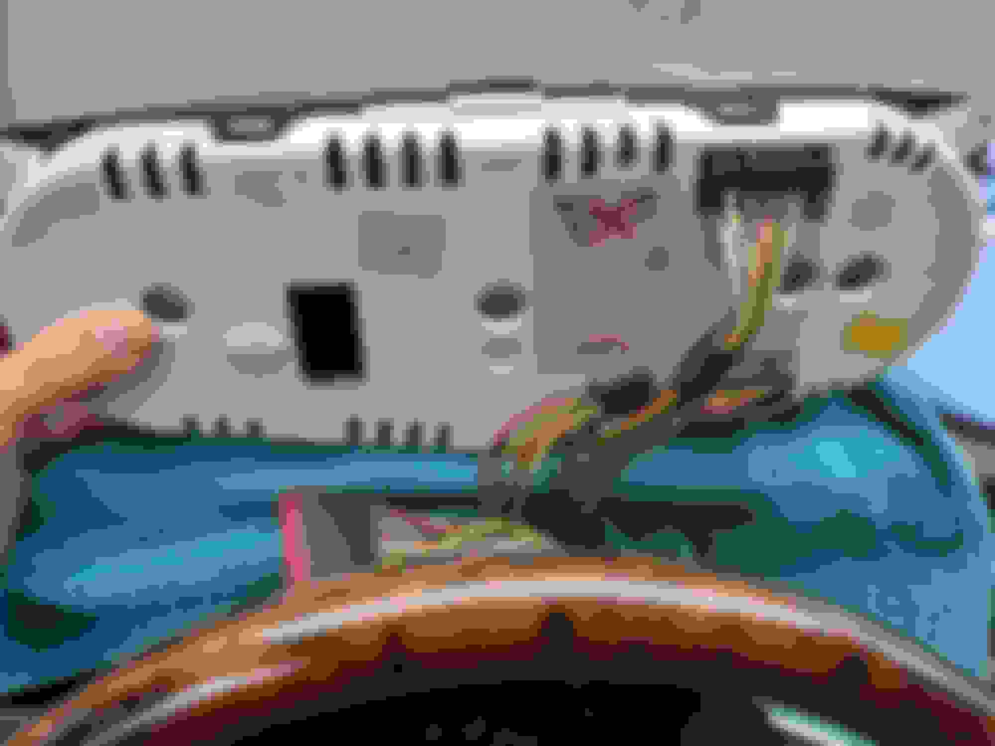
I have the instrument cluster accessible to disconnect (see attached pic of showing instrument cluster with all connectors still connected). Is the ICM inside the instrument cluster, and if so, which wires will I be disconnecting next to disconnect the ICM?
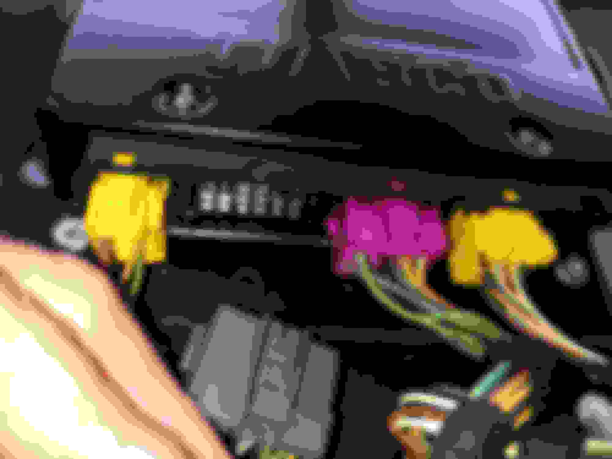
I have the ACM accessible to disconnect (behind the rear seat [see pic attached wherein may see I have not yet disconnected any of its various connectors). Which connectors will I be disconnecting next to disconnect the ACM?
I am progressing to that posted in this post, and then I will perform the next test (ohm meter on DLC 4 and 14) at the DLC. ICM and ASM.
ps. Life moves (often too) slowly in the garage sometimes while life continues to move fast in the office and home.
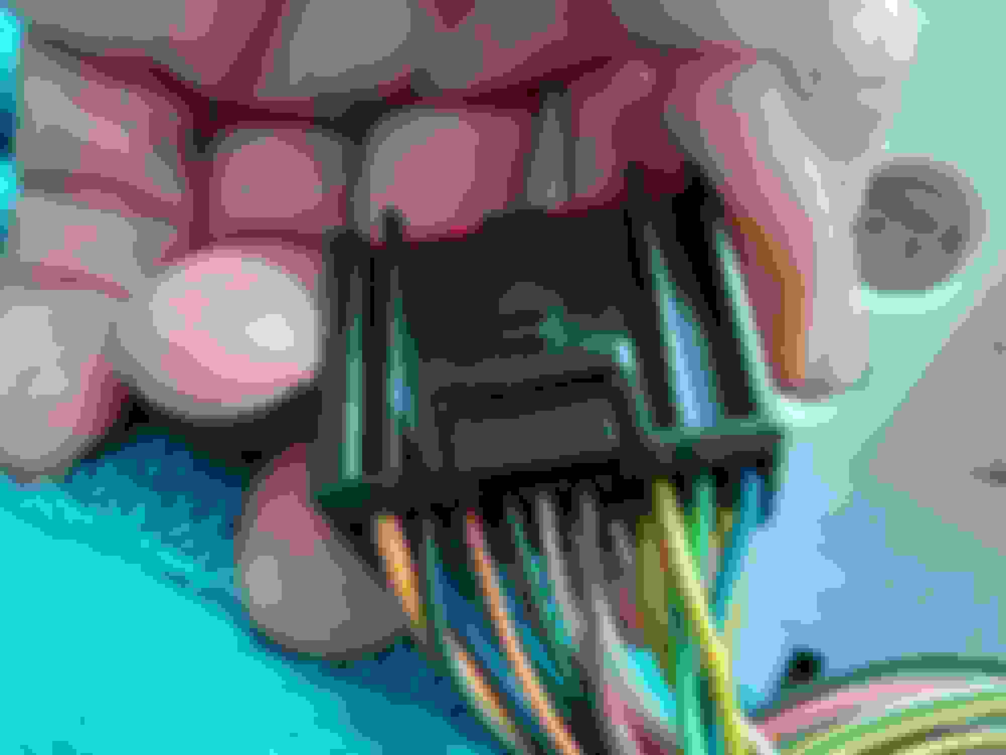
For the IC: IP6 - the one next to your thumb in the picture - it carries the CAN and SCP buss connections. CAN +ve is IP6-08 and IP6-09 is -ve.
For the ASM: CR88 is 9-way/Black CR88-7 and CR88-8.
Your battery terminals and clamps need cleaning badly. They look bad enough to throw all kinds of codes when you try to get it running!
03/24/22 ICM disconnected; ICM and ASM disconnected test ohms between DLC 4 and DL14
03/24/22 I tested
1.resistance between DLC 4 and DL14 with J=Gate connector, battery and ICM disconnected: result=0 ohms.
1.resistance between DLC 4 and DL14 with J=Gate connector, battery and ICM and ASM disconnected: result=0 ohms.
OldKarz, ps :I appreciate you; The the center ASM connector is not a 9 way; And yes the battery terminal clamps will be cleaned next.; Thanks for noticing ( I too noticed their condition and expected you would as well, yet I snapped the pic.
BTW: Tomorrow begins a JC of FL (JCNA FL chapter) show in Orlando; That will be fun!
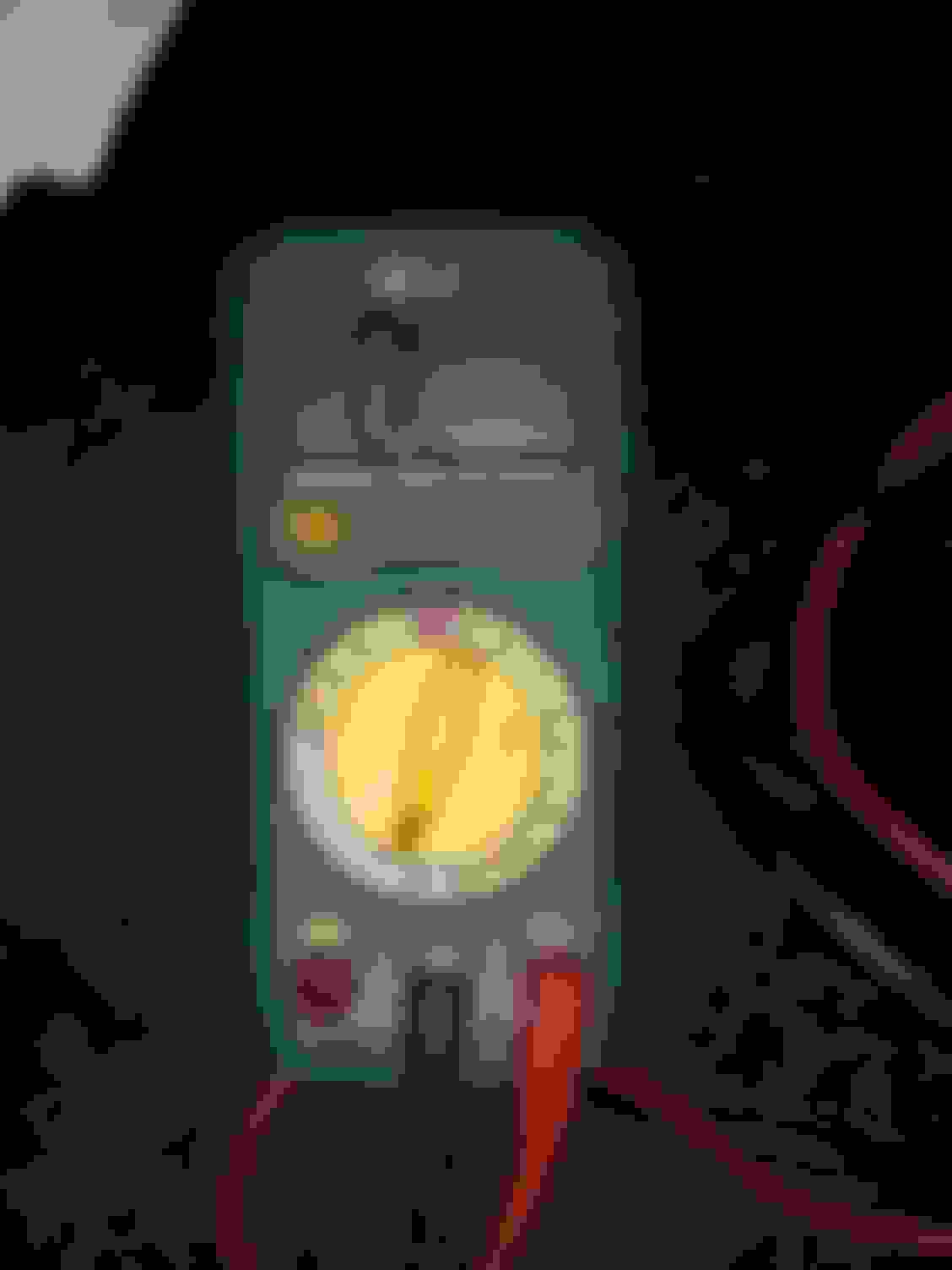
at ASM at ASM at ASM DLC and DLC 14 Only have one pic of the multimeter but both tests were 0 ohms
The reading on your Ohmmeter is not reading zero! It is showing OL which means it is a higher resistance than can be measured on that setting. You should see that reading even when the leads are not connected to any thing. This is assuming that the leads are connected too the OBD connectors suggested.
The reading on your Ohmmeter is not reading zero! It is showing OL which means it is a higher resistance than can be measured on that setting. You should see that reading even when the leads are not connected to any thing. This is assuming that the leads are connected too the OBD connectors suggested.
Hello OldKarz,
I too noticed on that multimeter that reading. I thought the batteries were getting low. I replaced the batteries today. Same display on all ohm settings. ( see pics). I can get another meter. Can retest and do more tests. She too wants me to keep searching for why shifter became stuck in park (no PRND lights) and no start. .
Does it read close to zero when you touch your black and red lead tips together?
The continuity test beeps , seemingly normaly when touch together the leads, and displays as seen in this post (I tried to post a video and my mobile devise created an mp4 which the forum didn't readily accept , so I converted the mp4 to a gif[and the gif didn't enable audio}
The continuity test seems normal. I did try the continuity test to ascertain the functioning of the meter, before I changed the batteries last week.
OK. That confirms your meter and leads are good. It also tells you that you do not have a short to ground on the CAN bus -ve, if all of your modules are connected. However do it on your M ohm scale to make sure you are more than 10k Ohms resistance to ground. Do the same for the +ve CAN bus to ground with the car battery disconnected. It should also be over 10k Ohms to ground.
Then connect your battery and put your meter on the DC 20 Volts scale and measure each of the CAN bus wires to ground. Neither one should be more than 5v.
As you know this is my most recent test,
"03/24/22 I tested
1.resistance between DLC 4 and DL14 with J=Gate connector, battery and ICM disconnected: result=0 ohms.
1.resistance between DLC 4 and DL14 with J=Gate connector, battery and ICM and ASM disconnected: result=0 ohms.
OldKarz, ps :I appreciate you; The the center ASM connector is not a 9 way."
I will do above pin out tests this week. I have most recently tested: CAN BUS -ve short to ground: test on 200 ohm scale and higher ohm scale as well
If possible, please confirm I interpret correctly the next 4 pin out tests:
-Test CAN BUS -ve short to ground: test on M scale resistance between DLC 4 and DL14 with battery disconnected, J=Gate connector disconnect, ICM disconnected, and ASM disconnected. Result (using M scale) should be = 0 ohms.,
and
-Test CAN BUS +ve short to ground: test on M scale resistance between DLC 2 and DL14 with battery disconnected, J=Gate connector disconnect, ICM disconnected, and ASM disconnected. Result (using M scale) should be = 0 ohms.,
and,
-Test CAN BUS -ve voltage: test on 20V scale voltage between DLC 2 and DL14 with battery connected and every module connected. Result should be no more than 5 V..
and, Test CAN BUS +ve voltage: test on 20V scale voltage between DLC 4 and DL14 with battery connected and every module connected. Result should be no more than 5 V..
ps,
This car's build date is 01/04/2004. Last week, when I removed the IC, I saw a distinctive marking of a date under the IC.
Below is a drawing I have from of a DLC pin out (but of an XKR). I post this drawing to show what I have as the DLC pin out and to mention my drawing is based on a pin out from a XKR.
Many of the connectors are presently accessible, and I can perform any previously performed test again. I mention this as there is one particular previously performed j-gate test (but based on a 2005-2004 manual) that has been on my mind (I have previously mentioned this j-gate test having wording that mentioned wires/components that I would like to clarify are accurate for my model year, and I will later post a pic of what my manual says for that particular j-gate test.
My manual has 2005 and 2004. I mention this car's build date and the date of the XJ8 manual I have, as I would still like to source a 2004 only manual to read the j-gate test test on another manual.
We need to get back to basics for the CAN bus as a whole. Then we can troubleshoot from there if there really is a problem. First - Connect all modules up! Then test the CAN Bus, with the battery disconnected. Use the Ohm meter on the 200 Ohm scale. Measure resistance across DLC 6 and DLC 14. Should be 60 Ohms + or - a couple.
Originally Posted by BReyes
I will do above pin out tests this week. I have most recently tested: CAN BUS -ve short to ground: test on 200 ohm scale and higher ohm scale as well With battery disconnected. Should be greater than 10k Ohms. Pins DLC 4 or 5 to pin DLC 14.
If possible, please confirm I interpret correctly the next 4 pin out tests:
-Test CAN BUS -ve short to ground: test on M scale resistance between DLC 4 and DLC 14 with battery disconnected, J=Gate connector disconnect, ICM disconnected, and ASM disconnected. Result (using M scale) should be = 0 ohms., All modules connected. Should be greater than 10k Ohms.
and
-Test CAN BUS +ve short to ground: test on M scale resistance between DLC 2DLC 6 and DLC 4 and DL14 and with battery disconnected, J=Gate connector disconnect, ICM disconnected, and ASM disconnected. Result (using M scale) should be = 0 ohms., Greater than 10k Ohms.
and,
-Test CAN BUS -ve voltage: test on 20V scale voltage between DLC 2 DLC 4 and DL14 with battery connected and every module connected. Result should be no more than 5 V..
and, Test CAN BUS +ve voltage: test on 20V scale voltage between DLC 4 and DL14DLC 6 and DLC 4 with battery connected and every module connected. Result should be no more than 5 V..
ps,
This car's build date is 01/04/2004. Last week, when I removed the IC, I saw a distinctive marking of a date under the IC.
Below is a drawing I have from of a DLC pin out (but of an XKR). I post this drawing to show what I have as the DLC pin out and to mention my drawing is based on a pin out from a XKR.
Many of the connectors are presently accessible, and I can perform any previously performed test again. I mention this as there is one particular previously performed j-gate test (but based on a 2005-2004 manual) that has been on my mind (I have previously mentioned this j-gate test having wording that mentioned wires/components that I would like to clarify are accurate for my model year, and I will later post a pic of what my manual says for that particular j-gate test.
My manual has 2005 and 2004. I mention this car's build date and the date of the XJ8 manual I have, as I would still like to source a 2004 only manual to read the j-gate test test on another manual.
OldKarz, Above table is a pdf file showing the tests performed last week, organized by test description and date. I created a Microsoft Word document and recorded many previous pin out test results too (in case I need to to do rework) to document pin point tests by description and date and results. Many of the modules are accessible now.
ps. I tried to copy and paste the table into here but the system would not keep the rows and columns and gridlines, so had to attach as pdf. I took two short videos of the multimeter screen so you could see the test results of the tests showing results at each scale setting, but the system is not enabling upload.
Looks like your bus is good voltage wise and the 60 Ohm resistance indicates you have end to end connections properly.
The bad news is that your meter's Ohm scales are not working properly. On meg Ohms you would get your reading of 1.004 M Ohms, which would be high but still very good. However on the next two scales you are showing 4.8 which would be 4.8 K Ohms. and finally only 1.76 on the 2K scale. The only ones that relate are the 4.8 K readings, which are probably right with the problems you are having. The 2K scale should read OL and the M Ohm should read 0.005 M. It is really not valid to guess at that conclusion with the errors.
However, using your 20K, scale check the -ve and +ve to ground again with the battery and the J-gate disconnected.
I ran a few Pin out Tests with new Multimeter. Thank you for your time. Pin Out Test: CAN BUS -ve short to ground 05/01/22 -Meter setting: Ohms and select automatic -Measure resistance between DLC pin 14 (CAN BUS low) and DLC pin 4 (Chassis Ground) Pin Out Test: CAN BUS +ve short to ground 05/01/22 -Meter setting: Automatic -Measure resistance between DLC pin 6 (CAN BUS high) and and DLC pin 4 (Chassis Ground) should be >10,000 Ohms Pin Out Test: CAN BUS -ve to ground -ABS module connector disconnected - battery disconnected -measure resistance between DLC pin 14 (CAN BUS low), to DLC pin 4( (Chassis Ground).
Do you know where I may obtain a 2004 Jaguar XJ8 Manual? Only model year 2004, not 2004 and other later model years too.
I am seeking a 2004 Jaguar XJ8 Manual as the manual I have was advertised as 2003-2008 but the page headers in this manual say 2005 Jaguar XJ8, and this car is an early 2004. ps. I will look for the j-gate test I previously read in this manual, and post pics of the wording to show you the j-gate test I am referring to, and why it leads me to believe the j-gate test in this manual with 2005 page headings is for 2005 and not for the early MY 2004.
From a previous test your bus seems good end to end with the 60 Ohm resistance, CAN+ve to CAN-ve. These recent tests with high resistance show there is no short to B+ or ground.
With those values it would appear your CAN bus is good shape! I cannot confirm that your meg Ohm readings are valid however since I have two shorts in my CAN bus - I would not really have thought they would be that high. Maybe some one else could verify a good systems value to ground.
At this point I would connect all modules, clear all your fault codes then reread and post them. One of your previous code posts looked like a power/ground condition causing your faults. If low power or marginal ground is anywhere along the system modules will loose communications on one or more buses. You need to use SDD and see what the actual voltage level for each module is. Some are not available but find as many as you can. Don't be too worried if some are very low or even higher than it is possible - it seems the conversion is not well defined. When engine is running, if it will, turn on headlight and air con etc and watch the module voltage values. Do the same with ignition on and engine off.

 02-28-2022, 01:16 PM