When you click on links to various merchants on this site and make a purchase, this can result in this site earning a commission. Affiliate programs and affiliations include, but are not limited to, the eBay Partner Network.
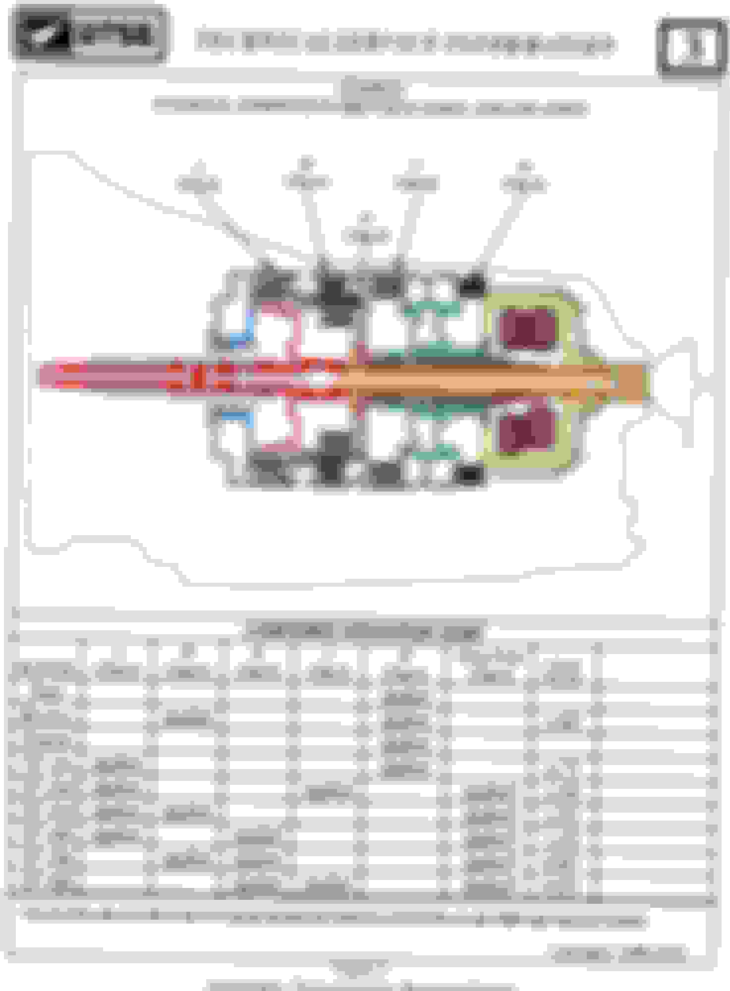
This document was in Don B's manual he posted.
Invaluable to see which clutch pack is where in one diagram as
A clutch pack has 5 friction plates,
B 5,
E 7,
C 5 and
D 7.
Very confusing otherwise.
None of the above is covered in the videos I have watched.
Sets of 5 are thicker than the sets of 7.
You can also see very easily how the different drums/carriers relate to each other.
Looking at a standard manual with elements on different pages is not that simple.
Where's the link to Don's manual John? I like this view as well. The ZF manual has a blowup of each clutch pack and individual part numbers, but no diagram like this.
Edit - disregard. I found it. I was looking for a separate thread. Thanks Don!
I saved it as a PDF and uploaded to my ZF Dropbox John if you want to download that too. I'f anyone else wants access, PM with your email address and I'll grant you access.
A clutch pack has 5 friction plates,
B 5,
E 6,
C 5 and
D 7.
Sets of 5 are thicker than the sets of 7.
My E clutch had 6 friction plates not 7. Also in the kit I received it had some "thin" plates and some "thick plates". There is about 0.5 mm difference between them.
I got one thick plate mixed with the thin plates and could not get the snap ring in the drum to hold all snug but not overly so as there has to be room for movement otherwise the clutch will be constantly "on" that is what I am thinking.
Swapped and all is fine.
Also I managed to disassociate my drums from their original clutch packs a VERY silly thing to do!
So now I have to figure out which take the thick plates and which the thin and no documentation anywhere to give me an idea!
When inserting the snap ring in a drum on top of the clutch plates It has to go in easily if you have to press down very heavily to get the snap ring in something is wrong I think.
Replacing two "piston ring type" seals on the shaft of the pump. Measuring a new "thin" friction plate. Three more "piston ring type" seals replaced on this shaft. Showing where the snap ring fits to hold the "lampshade" drum extension on top of the clutch plates in the A drum and over the E clutch assembly. The snap ring is loose in this pic
If it were not for the pronounced leak I experienced with this transmission I would suspect the valve body to be the cause of the hard fault I experienced.
Reason that I think that is because I have seen no obvious damage/excessive wear anywhere in this transmission.
The possible exception being the large bushings where the pump goes into the A drum.
Now I could simply replace the valve body while I am doing all this however if I did that and the transmission worked like a charm I would never know for sure!
So I will press on and use my original valve body with the new solenoids and see what happens.
Also not sure what fault a faulty torque converter would cause?
Found this spacer which only appeared on my work area this last day. In the ZF6 catalog a spacer is listed on the shaft at the back of the pump. So started to take the A drum apart. This is an old shaft piston seal which I am showing because I found part of one when I started to take A drum apart. They are metal. No way can I separate the A drum from the pump. I surmise that a broken piston seal is jamming the shaft in place.
If I use a press to try and separate everything I probably will score something badly even tho its probably one tip of that piston seal protruding out from the slot in the shaft and stopping me from separating things. My press is in MA anyway where I will be going for several weeks soon.I will take the assembly up with me and try the press anyway. On surveying damage I will decide on my next step.
A used pump plus A drum is a couple hundred dollars so will think about this option over the next few weeks
Showing a snap ring holding a bearing in place. If I could get that off maybe I would have some access? Will research that. My heavy duty snap ring tools are of course in MA!
Internal, external, ratcheting, snap ring remover, that has a gang of optional tips.
As well as several that come with it, not cheap, but works great.
Still a place around that sells REAL taps,dies,drill & torx bits, REAL tools for machine shops.
If I use a press to try and separate everything I probably will score something badly even tho its probably one tip of that piston seal protruding out from the slot in the shaft and stopping me from separating things. My press is in MA anyway where I will be going for several weeks soon.I will take the assembly up with me and try the press anyway. On surveying damage I will decide on my next step.
A used pump plus A drum is a couple hundred dollars so will think about this option over the next few weeks
There's a transmission shop down the road from me where the owner has been doing it 40 years and counting. He also build rat rods for rich guys. Point being, if you're near a trans shop you trust, you might bring in the A drum, explain the situation and they may have a solution short of a replacement. If they carry the drum into the shop with a chisel and maul hammer in the other hand, best stick with your current plan. I would only leave it with them if they've seen this kind of issue before and know how to resolve. Otherwise, you appear to be more proficient than most.
Looking at Ebay at pictures of these items showed me that nothing would be gained by taking out that snap ring.
After taking time to THINK things thru I realized that the two parts, the drum and the pump, should rotate separately Tools used. Ended up only needing the strap wrench. Separated !!!!! Are my new bushings to small on the inner diameter OR was one slightly askew? We will see.
Those scratches you see are where I used a large screwdriver to lever the two components apart while twisting at the same time. Took a few tries. 4 hands would have helped! The two piston ring seals look fine.
.
Broken piston ring type seal actually came from another shaft and nothing to do with the one I thought it was. This is the shaft it came from. I used an original seal to replace it. Another seal to replace.
Inserting shafts with these piston type rings is tricky as they protrude outside the diameter of the shaft. In videos I watch experts seem to nonchalantly slide the shafts into place with no problem.
Inserting shafts with these piston type rings is tricky as they protrude outside the diameter of the shaft. In videos I watch experts seem to nonchalantly slide the shafts into place with no problem.
Is there any way you could use some kind of seal protector over the shaft and ring to smooth the transition? I know for my dirt bikes I have them for helping to slide fork seals into place without ripping them. I hate to say it but would a condom work (extra thick, pre lubed obviously)?
So I knocked the two bushings out of the A drum. One was destroyed because I could not get at the backside of it as it sits on a lip . The other which is supposed to protrude above the lip of the shaft opening so as not to block an oil way I got out with no damage.
Before taking out the 2nd bushing I tried sliding the A drum back on the pump shaft and it would not start to go on easily so stopped.
So placed this undamaged bushing over the journal on the pump shaft and it fits just fine and dandy!!!!
I must have had it skewed very slightly when I drove it in and that is all it took to cause a bind.
When the new bushings arrive I have to figure out how to drive that one bushing in evenly and still leave it sitting up a bit and not block the oil way.
These original bushings btw I think were worn quite a bit.
I also removed those piston style sealing rings before trying all of this.
I think I will be ok with these so long as I turn the A drum constantly when placing it on the shaft.
So the issue I was dealing with today was the fact that when I load the clutch pack into the B drum there is only just enough room to lock in the snap ring and that binds the clutch pack way too tight.
The friction plates are the thin ones but the steel plates are the thick ones.
To cut a long story short I swapped 2 thick steel plates with two thin ones from the A pack.
Now both sets of clutches rotate freely when locked in place with snap rings. And they are dry right now.
In the repair manual there is a lengthy process detailed for measuring clearances of clutch packs but nothing whatsoever about how to achieve the correct clearances.

 01-12-2020, 06:42 PM