When you click on links to various merchants on this site and make a purchase, this can result in this site earning a commission. Affiliate programs and affiliations include, but are not limited to, the eBay Partner Network.
For each drum measure the clearance between the snap ring, holding in the clutch pack, and the clutch pack when compressed against the base of the drum. Note how freely they can be rotated.
Keep the clutch pack associated with its drum AND the snap rings as they differ in thickness.
Note the type and number of friction plates associated with each drum and measure their thickness to determine thick or thin.
My kit just had two types thick and thin.
The above will help immensely when replacing clutch friction plates.
Make sure you see all washer shims and note where each came from.
Some are difficult to spot because they are thin and stick to their location...until knocked loose by accident.
D clutch and drum in place with snap ring almost in place. Snap ring in place after some effort. Clutch and drum in place with quite a bit of wriggling about. Would be much easier if trans was vertical. E clutch interior "drum" in place. The friction plates have to line up properly in here. E clutch drum and lined up friction plates. E clutch in place.
The next steps are awaiting parts. New bearings and also a new seal for the front of the pump. Somehow managed to damage it.
The weight of this transmission is at my limit for lifting on my own so when ready to put final drum in place that will take place on the garage floor.
If it were not for that d####d bushing I would have had the whole thing assembled and ready for an air test.
Rear seal in place. Put it on flange shaft first so that I could place the shim washer on the shaft then insert seal in place. Will peen the new 12 point nut later. You can see the bushing that is a problem as it must not be driven all the way in. In place ready to be driven in. The oil way hole can be seen here it is the one on top the smaller one. NOTE the spacer washer on top of that journal. Here is the bushing all the way down on the shaft where it covers the oil way. If driven all the way in in pic #3 it would block this oil way. I have confirmed that with measurements.
So not messing around with this bushing. I have ordered another bushing set that I believe will do the job with a driver sitting below the bushing to prevent it going in all the way.
This bushing is only 7.4mm in depth and carries a lot of weight. To be fair there is the other bushing about an inch down from this bushing and is of greater depth. Still I do not like the design.
In at least one rebuild video of a low mileage, 53k miles, ZF6 this bushing was badly worn along with the other one.
The bushing that I removed without damage is just the right size to place down on that journal, where it will block the oil way, to allow me to drive in the new bushing to the correct depth.
The problem then will be removing that bushing blocking the oil way. It actually pulls apart with a jigsaw type tab which I will cut off allowing access to pry it off.
That bushing in question CAN be driven in all the way without blocking the oil way.
I just did it. I placed the original bushing as a stop on the bottom edge of the journal and knocked a new bushing down in place and it went in all the way.
Took the stop bushing out and oil way is visible.
What is more the A drum when placed down on the shaft rotates freely!
Anyway I still need a new lower bushing which I did not need to take out! It was not the cause of the binding issue. Oh well.
I thought that I had ordered a complete kit again however it turned out to be a "kit" of 5 upper/front bearings so I have 4 spare now.
So I have ordered yet another kit like the original one. Could not find just the individual bushing that I need here unlike the kit of 5 bushings. New bushing in place. My measurements were wrong because I did not have the spacer washer in place!
Here we have it. Bushing is proud as it was originally before disassembly. I used two bushings stacked on top of each other. The top one being the clipped short one. I then placed the A drum on top with a piece of wood across it and pounded down a couple of times.
I do not understand why this bushing has to be proud as it does not block that oil way when all the way in. I am sure the ZF folks have a good reason?
Note the 4 tabs sticking up. There is a slot on the inside of each that holds the planetary gear snap ring. Rear shaft of pump on which the A drum is positioned. The splined gear takes the sun gear of the planetary gear set. Two piston rings in pace on shaft. A drum in place with sun gear on top of spacer washer. Underside of planetary gear set with snap ring in place. Planetary gear set will NOT snug down in place. Ready to take the A drum and B drum set. Had to raise it to the vertical to manage that very lengthy process. A drum with B clutch set on top. Kit came with new washers for pump screws Finally pump is in place and screws hand tight. Took a long while to get it to seat and then to line the screws up.
I made the mistake of putting the A drum on the pump shaft without the sungear set in place. That meant I could not snug the sungear set down in place because the tabs that hold the snap ring were too low so the snap ring would not go down enough to click into those slots.
It took me a while to finally figure that out. Putting the sungear on the A drum BEFORE placing it o the shaft was the solution.
Lining up the A drum and B drum set to snug down into the transmission was a lengthy process of wiggling and rotation of shafts including the output flange.
The same thing with the pump. Transmission has to be vertical to succeed with this procedure.
Next steps are to torque down the bolts in the pump. Which I installed with a new ring seal. Then to do an air test.
Assuming that goes well I will install the mechatronics valve assembly and pan etc.
So ran the air check on the drum clutch packs and failed.
The B drum pack did not move. The clutch pack is too tightly packed.
There are two thickness measurements for the steel clutch plates and my B drum has the thicker of the two. I need to replace at least one with the thinner plate.
The A drum has the thinner plates and I have already swapped one of these with a thicker one from the B drum and it is ok on movement.
So I need to obtain some thinner plates and new they are VERY expensive.
So I have purchased a used A drum complete with clutch pack on Ebay. I made a low ball offer and it was accepted. $53 with shipping and of course these day tax.
When I watch clutch pack clearance checking on YouTube there is quite a bit of movement with these packs but no explanation on how to adjust.
The repair manual gives a very tortuous write up on checking the thickness of a clutch pack but no details on how to adjust.
Update: Just watched a video where they say "adjust the shims" to get the correct clearance.
So the packed A drum from a Hyundai arrived yesterday. Slightly different design from my A drum in that the notches that hold the snap ring in place are of a different design all else the same.
First thing I did was to look at how tight/loose the clutch pack was in the drum and it was such that I could move the pack up and down quite easily with about 1.5mm movement but that is a guess.
All steel clutch plates were "thin", as expected, so replaced a thick plate in my overly tight pack C Drum with a thin one and I am satisfied with the clutch pack movement.
I spent hours trying to get the drums back in place in the transmission but could not get something to seat properly no matter what I did.
Gave up but at 2.00 am in the morning got up and had another go and hey presto got everything in and seated properly and was able to move the visible clutch packs with no binding.
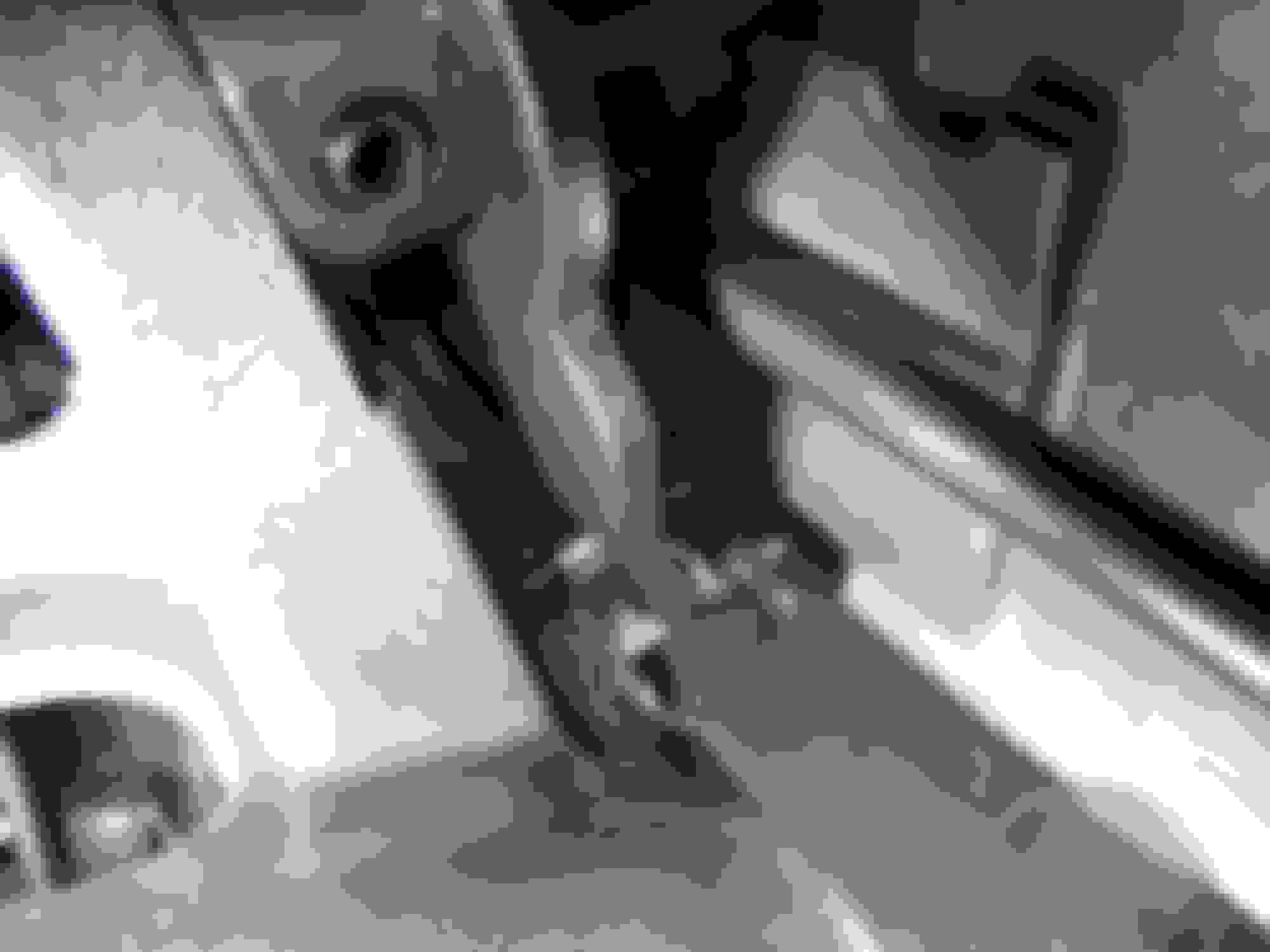
However something dropped out of the transmission when I was jostling it around see pics.
This roller bearing dropped out. If you look carefully at the flat spring metal held in by two screws you will see a fork at the top end. That is where the roller bearing rests. It is held in place by the force of the gear selector plate and the steel spring pressing up. Roller bearing in place with notched gear selector plate on top.
What I did was to move the gear selector too far so that the gear selector plate with notches in it moved off the roller bearing and so it simply fell off its perch. Very easy to do.
It was a devil of a job getting it back in place!
Carried out an air test and all seems pretty good to me.
So will put on the valve body and pan and slide everything under the car where I have to then mate the torque converter properly without damaging the pump seal and then get this 200lb beast onto my hydraulic lift.
Once I have reinstalled the transmission and refilled it there will be two outcome possibilities:
One I get error messages immediately.
Two it works but will need re-calibrating with SDD.
Depending on the error messages I will consider replacing the valve body and go from there.
I am looking at used XJR transmissions as an option or even taking my transmission to a specialist. We will see.
John,
Fingers crossed.
If you need a complete valve body and TCM - reach out as I have one and will be throwing it up for sale. (Along with a bunch of other Jaguar items - time to clear up the shelves)
This has been a fantastic read John. Here's hoping to your success! Graham posted this out in the DIY of the XK section. I think most there are in agreement. We will not be attempting this but am truly impressed with the work you've done, win lose or draw.
I tested the gear mechanism to make sure it worked and it locked up the transmission in park and moved thru the gears.
Put the torque converter in place very carefully and it went into position with some careful jiggling.
I then jacked up the rhs front to enable me to gradually push the transmission with the bell housing just clearing the body between the wheel and wheel arch.
All I have to do is raise the trans high enough to get my hydraulic lift under it . When I sayall this will be quite a task.
I have part of a trans support, designed to hold a transmission, which I bolt on to the hydraulic lift with a piece of wood on top of that about the size of the trans pan.
The trans support I bought when I took my diff out a while ago so I am getting my moneys worth out of it.
At the same time I am replacing many front suspension components on my truck.
I used two bolts one either side halfway up the bell housing to screw the bell housing towards the engine once I knew the two were "flat to flat".
Most of the bell housing bolts are in just have to do the top 4.
Got the starter motor bolted up and wow was that a pita until I figured out I could just touch the top bolt by squeezing my fingers between the engine and the starter.
I was the able to actually finger tighten it using fingers either side of it. Getting that bolt started tho took a while.
Got the first torque converter bolt hole lined up and ready to torque in. The mechatronics wiring has been zip tied to the two wiring supports on the trans housing.
I was thinking about the pump and plan to inject some LF6 in the cooler input port so hopefully it is "primed" somewhat. This will be a fill from a totally empty unit.
Have been sidetracked by other issues for the time being.
Transmission is bolted back on the engine. Torque converter bolted in place all bolts torqued down not without some difficulty.
Transmission support bolted in place so my "transmission lift" is out of the way which helps a lot.
Mech connector in place.
Prop shaft is bolted back but still have to torque these bolts properly.
Gear shift mechanism bolted back in place along with the cooler lines.
So still have to put catalytic converters back in place along O2 connector sockets to plug in.
So getting close to the reality check.
I aim to tilt the trans fill plug as high as reasonably possible by jacking up the rhs of the car to get the initial fill done.
Will start the engine for all of 2-3 seconds only so that some LG6 gets pumped into the torque converter, etc.
Will then pump more LG6 in until it drips out then put in plug temporarily and level the car ready to do the fill process which will be a mix of LG6 and Mercon SP.
Whether all of this helps or makes sense I do not know.
I run an ongoing updated list of what I need to do so that I do not forget what needs to be done next.
Doing all of this would be a heck of a lot easier if I had a lift!!!!!!

 01-15-2020, 06:13 PM