When you click on links to various merchants on this site and make a purchase, this can result in this site earning a commission. Affiliate programs and affiliations include, but are not limited to, the eBay Partner Network.
I have a 1996 XJS with the 4.0 AJ16 on 120k miles.
From what I can tell, it's not entering closed loop mode, which is causing raised CO, HC and CO2 levels, which has caused the failure of one of the CATs in the Y pipe of the exhaust (recent exhaust gas test showed good emissions from one tail pipe, and bad from the other).
The lambda readings are both around 1.270v - I understand they should switch high/low, and read upto 3.5 volts?
From the data, coolant temperature is around 90C and air temp (today with ambient around 21C) was around 38C
There are no stored fault codes.
Work so far:
Replaced both O2 sensors
Replaced exhaust Y piece with CATs
Replaced air temp sensor (was seeing upto 60C air temp previously - although ambient air temp was higher).
No improvement so far. Data from other sensors looks as expected.
Any suggestions what to look at next?
EMS power relay must click closed ( swapping options and fuse # 20 and # 7 , # 7 to control the relay ? )
There is an external diode involved on the relay control circuit ....................
Fuse # 7 goes through the inertia switch for some reason , you can jumper between the 2 white wires on the inertia switch connector on your XJS per XJS wiring guide
Thanks, however the XJS doesn't have a right side engine compartment fusebox, only a left one and no fuse for the O2 sensors (according to the electrical guide I have, anyway).
Regardless, I have checked every fuse in the engine bay, all are good.
I can open a connector and check if the heater voltage is present.
OK, some confusion here because my car is a UK right-hand drive model - and all positions are reversed.
Therefore the relays and fuse box contents that the electrical guide shows on the right side of the car (page 10) are on the left side.
The fuses there are all good, and I can feel the ECM relay operate. If I remove it, the engine cranks but doesn't start, so the relay must be working,
EMS " power " relay clicking I see you have 2 EMS relays
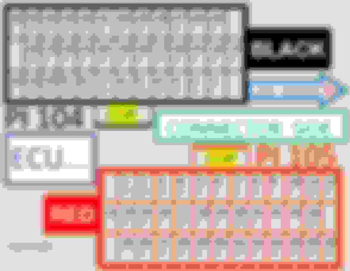
From the diagram, there's a EMS Power Relay (white socket), and an ECM controlled relay (blue socket).
I removed the power relay - and it wouldn't start.
The " power " relay as the White / Brown wire going on down also powers the coils as power " sitting " on them , 6 timed ground path wires from the ECM produce the spark
I've done some quick testing.
I measure battery voltage on one of the pins of the O2 sensor connector. I also connected one of the old sensors and could feel it heating.
So we can eliminate O2 sensor heating as a potential cause.
Reading up on events that can trigger the check engine light (in the Engine management SELF-STUDY TRAINING COURSE 801S document, page 28), one of them is: Engine control module fails to enter closed-loop operation within a specified time period.
The check-engine light is working - it comes on before cranking, but doesn't again, and there are no stored codes. So the ECU doesn't consider there to be anything wrong.
Is a faulty ECU a possibility?
You can read resistance through the sensor pigtail at pin 3 and 4 for the heating element in the installed sensors
Connectors clean ?
Then we get back around to the ECU connectors
O2 sensor return signal wires A and B
Sensor return wires shield ground terminals clean to protect that signal
The pin / sockets positions will be the same between the X300 and XJS just different wire colors ( both O2 sensor and ECU connectors )
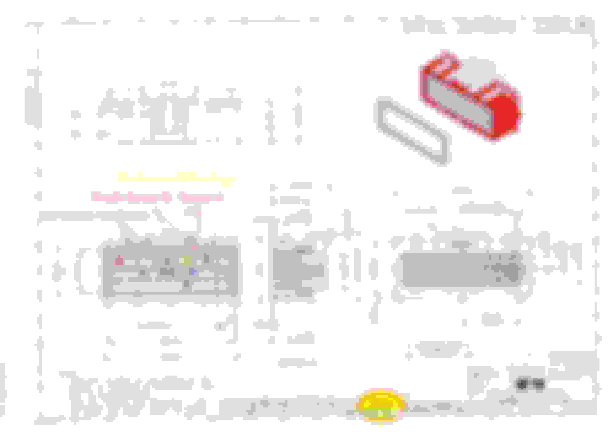
The sockets can be missing 1 of 2 pinching tabs for best connection and corrosion on the wire as it enters the socket wire crimp
You can have fresh sockets in the unused socket positions as there are many
You should only have downstream sensors ( S2 ) for England
ECU connector ( red ) for return signal :
Red 18 aft bank cylinders
Red 16 fwd bank cylinders
Black 4 both O2 sensor heater grounds
And we get to ECU grounds including heavy external ground wire attached to ECU case ( sometimes missing )
ECU pins / wire ground terminals ( about 2 or 4 )
working
O2 sensor connector for heater :
pin 3 White / Pink wire on the car side
To pin 4 White / Brown wire on the car side
The ECM power relay can read battery volts but not carry the current to properly run the devices ( burnt contacts inside the relay , relay swapping option ? )
You can feel some heat but is it enough as exhaust gasses run past the sensor
The ECU is a first-generation design working out the real-world bugs as they came up with codes ( or even if a code shows ) so best first try from engineering
OK, some confusion here because my car is a UK right-hand drive model - and all positions are reversed.
Therefore the relays and fuse box contents that the electrical guide shows on the right side of the car (page 10) are on the left side.
The fuses there are all good, and I can feel the ECM relay operate. If I remove it, the engine cranks but doesn't start, so the relay must be working,
interesting you say that.
on the x300 (and all other cars i know of) things like fuseboxes always remain in the same spot regardless of RHD or LHD.
standard practice is to move as little stuff as possible to keep manufacturing as standard as possible.
what i find even more interesting if this is the case is the fact the the guides are made by jaguar who are a british company therefore RHD is going to have been the primary manufacture method.
when i read the elec guide for the x300 i can always be certain that what it say is the correct location in my car which is RHD.
Yep, seems everything is reversed. EG, the ECU location is in the left (passenger) footwell, yet the diagrams show it in the right side.
Maybe there is a RHD version of the docs or the XJS somewhere?!
1. oxygen sensor heater to reach a certain temp. If you have replaced them, I'm going to assume they're good.
2. TPS connected, and within range. With an OBD2 reader, you should see something in the range of 12% open when at idle.
3. MAF sensor readings within range.
4. Coolant Temp must get to 160F, i believe. This is a common problem. The sensors cost about $20 and should take you about 5 minutes to replace. Just make sure the engine is cold!
1 - Yes, both replaced and confirmed heater voltage reaching them, and that another sensor connected to plug heats up.
2 - I can't remember the exact value, but it was certainly around that figure. Will double check it when I next collect the car.
3 - I recall seeing the values change with engine speed, again can check exact figures.
4 - 160F is 71C - temp was around 90C when I checked it.
Also, from what I see from the documentation, failure to go into closed loop after so long should cause the check engine light to come on, and it doesn't. (The light works and illuminates before cranking)
So i'm suspecting a faulty ECU now.
Also, from what I see from the documentation, failure to go into closed loop after so long should cause the check engine light to come on, and it doesn't. (The light works and illuminates before cranking)
So i'm suspecting a faulty ECU now.
It does not do that on the 1996 XJS. You could drive for years in open loop and not know. (other than mileage)
I did have an ECU go bad which did just that...keep the car in open loop. I had someone try to repair it and it is now in worse shape. Luckily the x300 ECUs are easier, and cheaper to come by.
Did you use an OBD2 reader to check the coolant temp sensor?
The TPS sensor at the idle mechanical stop should be around 12 % and a voltage value of close to 0.60 volts DC ( middle wire ( X color ) on TPS connector as it comes over the fuel rail ) , do not remove or adjust TPS sensor yet , this test can be performed with engine not running but key in run , TPS connector must remain installed
This middle wire value will climb toward but not on 5 volts DC
The MAF sensor will read 1.2 volts DC on it's middle wire at the proper idle speed and will climb toward 5 volts DC on throttle up
Vee had a suggestion to give the MAF connector pins / blades a slight twist to make better connections
This will be about 4 grams / second up to around 175 grams / second
There is a software error on the live data readers that the MAF given must be multiplied by 10 or 100 to be correct
There is a TSB to not throttle the engine up unless on the road , probably to do with transmission cooling as it has no transmission cooler ( the other supercharged or V - 12 does with the different transmission ( GM ) )
" Also, from what I see from the documentation, failure to go into closed loop after so long should cause the check engine light to come on, and it doesn't. (The light works and illuminates before cranking) So i'm suspecting a faulty ECU now. "
Don't purchase another ECU just yet , ECU connector inspection ?
With the thermostat keeping the coolant below 92 C and closed loop is 88 C there is little margin to hit the closed loop temp return to ECU value , so ECU connector inspection
By the CEL light not coming on when expected ( no closed loop ) might be expecting the ECU design to be perfect against written text as they " got it together " from the ECU manufacture ( Lucas - Semans ? )
This is the ECU used in V - 8 application , see page 52 and 63
NAS in the text is North American Specification so yours may not show
The TPS sensor at the idle mechanical stop should be around 12 % and a voltage value of close to 0.60 volts DC ( middle wire ( X color ) on TPS connector as it comes over the fuel rail ) , do not remove or adjust TPS sensor yet , this test can be performed with engine not running but key in run
This middle wire value will climb toward but not on 5 volts DC
The MAF sensor will read 1.2 volts DC on it's middle wire at the proper idle speed and will climb toward 5 volts DC on throttle up
Vee had a suggestion to give the MAF connector pins / blades a slight twist to make better connections
This will be about 4 grams / second up to around 175 grams / second
There is a TSB to not throttle the engine up unless on the road , probably to do with transmission cooling as it has no transmission cooler ( the other supercharged or V - 12 does with the different transmission ( GM ) )
" Also, from what I see from the documentation, failure to go into closed loop after so long should cause the check engine light to come on, and it doesn't. (The light works and illuminates before cranking) So i'm suspecting a faulty ECU now. "
Don't purchase another ECU just yet , ECU connector inspection ?
Thanks for the info, will check when I next have the car here (it's in storage a few miles away).
The ECU was disconnected a few months ago when I had some of the trim removed, and the contacts didn't have any corrosion - but I'll check them again.
It does not do that on the 1996 XJS. You could drive for years in open loop and not know. (other than mileage)
Really? The Engine management document (SELF-STUDY TRAINING COURSE 801S, page 28), in the info about events that can trigger the check engine light, one of them is: Engine control module fails to enter closed-loop operation within a specified time period.
Mine has killed a catalytic converter and failed an emissions test because of it :-/
Originally Posted by Vee
I did have an ECU go bad which did just that...keep the car in open loop. I had someone try to repair it and it is now in worse shape. Luckily the x300 ECUs are easier, and cheaper to come by.
I read another thread somewhere where someone had the same issue, cured with a replacement ECU.

 08-19-2024, 08:02 AM