When you click on links to various merchants on this site and make a purchase, this can result in this site earning a commission. Affiliate programs and affiliations include, but are not limited to, the eBay Partner Network.
Almost done, I still need to fabricate stainless steel heat shields for exhaust manifold and down pipe this weekend. Runs great with no "codes", all O2 sensors, air pump feed and the EGR connection accommodated. Using 30lb injectors, and a ECU from a 1997 supercharged jag. Boost is adjustable from 4lbs - 25lbs, currently adjusted to 8lbs. Running a T3 .63 70 A/R turbo that begins to spool at 2200 rpm and makes peak boost at 4000 rpm. The turbo seems to be perfectly sized (lots of research and online calculators) and pulls hard stop light to stop light.
Laying out the exhaust manifold flange after taking dimensions from a new set of exhaust gaskets. Tweaked 1:1 scale drawing elements until gaskets lined up with flange ports and stud holes.
Flange ends are oval shaped. Fabricated die to press and flare ends. Also required pressing with a tool over the round end to prevent it from distorting.
Invested in $100 head from eBay for mock up and to use as a fabrication jig.
The used head keeps on giving.
Fabricated M/F harness extension to avoid cutting/splicing into my car's harness. The extension harness used to wire an external ECU to for data logging; fuels trims, IAT temp, injector duty cycles, timing, MAF, boost pressure etc.
Because the engine's static compression higher than I'd like for a boosted car I thought I might have to use an external ECU to spray water or methanol at certain boost levels. In the end, using 93 octane gas with really low IAT temps the external ECU was not necessary.
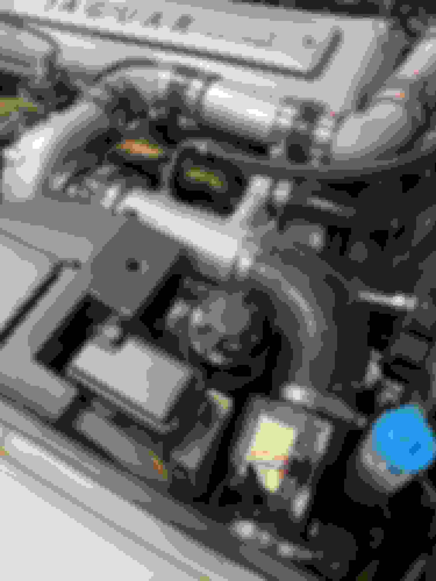
Turbo's hot side. The turbo install displaced the PS pump reservoir and required I fabricate custom A/C hoses by welding and crimping new bead lock fittings on factory hose ends. I also sewed hose sleeves from pieces of heat tape to cover all lines and hoses.
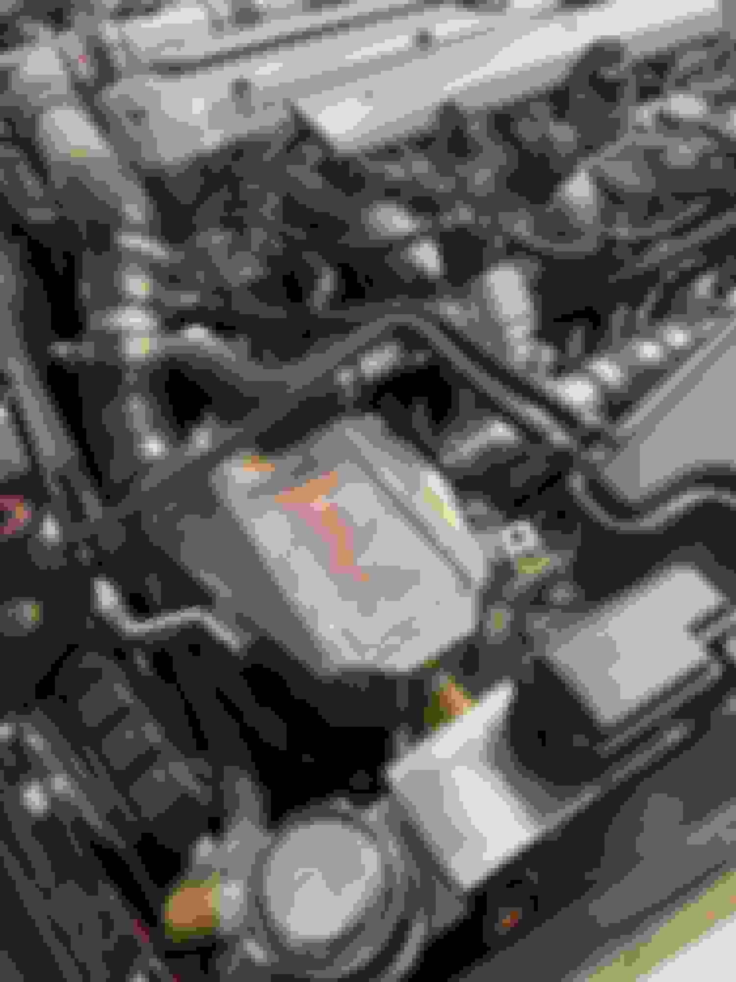
Turbo intake side. The PCV connection and BOV air returned to the turbo inlet. Moved the MAF and installed filter element in fender after removing rubber grommet; I'm assuming the grommet/plug there for RHD model's filter snorkel.
Looks simple but it took several hours to fabricate an air inlet temperature sensor fitting for the silicone elbow just before the throttle body.
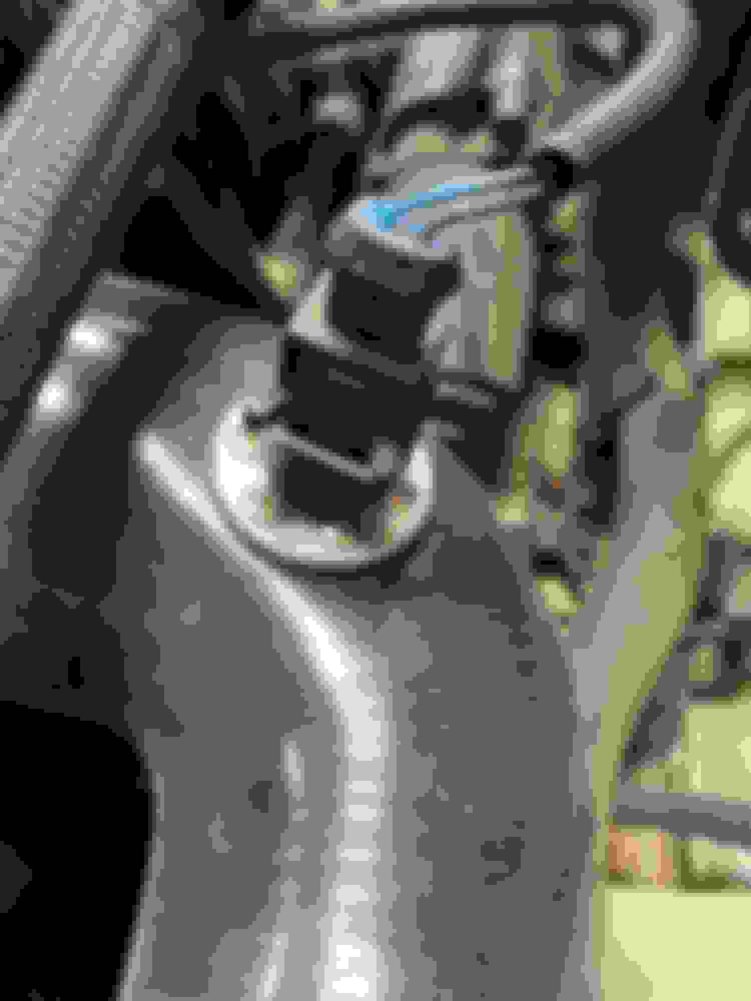
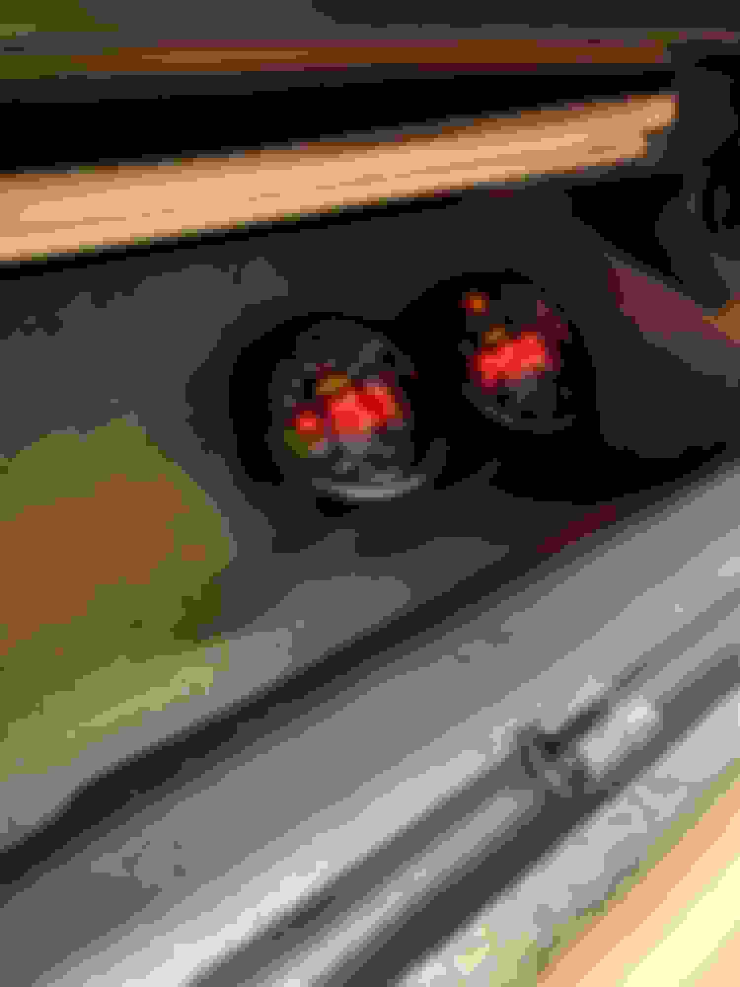
Water cooled intercooler. Bosch water pump mounted behind bumper just below the fan relay assembly. Pump controlled by front fog light switch. Modified body processor module wiring harness to not require headlights or running lights to be on for fog light control. I also ran "switched" power from RH engine fuse box to fog light relay to avoid leaving my water pump on after car was switched off.
Boost and AFR gauges mounted in my glove box. AFR reads 12.50 at 8lbs of boost. I could dial the boost up until I ran out of injector or fuel pump but since this is my daily driver, I'll leave it turned down... for now.
Moved the MAF and installed filter element in fender after removing rubber grommet; I'm assuming the grommet/plug there for RHD model's filter snorkel.
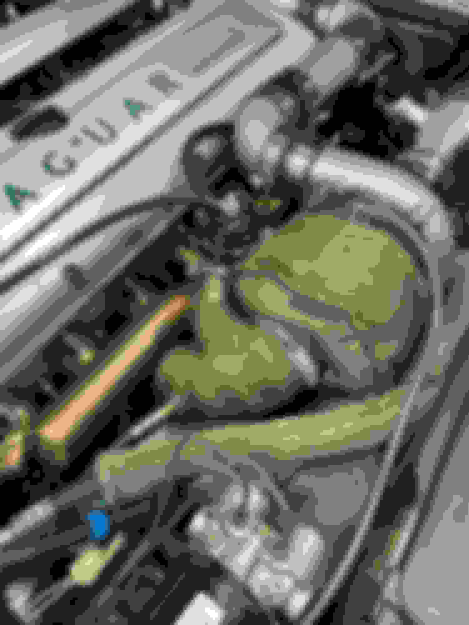
Larry, you should recognize my oil feed solution; it's your idea! Also posted is a picture of my oil return solution. You'll notice I had to radius the edge of the block to get AN-10 90 degree fitting to clear when installing it. Did the LTFTs ever return to normal on your SC swap?
For anyone interested, I was able to fit the water to air heat exchanger behind the lower bumper opening. For good measure, I fabricated a license plate bracket to the left of opening to accommodate more air flow to the heat exchanger. I will repaint the car soon and I will fill the holes for the license plate bracket.
Thanks to all who have commented, I appreciate your support and encouragement.
Richard- the only parts you see are in the photos. What you can not see are the totes filled with parts I could not make work or use. It seemed I had to fabricate two of everything before I could finally get it sorted out. I'm hoping by providing the attached photos, persons will not have to go through the same discovery I had to should they decide to go down the same path.
Towards the end my wife giving me very strange looks before heading out to the garage after receiving yet another Amazon or eBay package. In the end, when I saw and felt the boost, saw my owner manuals fly from the glove box and land on the passenger seat. I knew it was worth it.
Thanks to you and all for taking the time to respond to my posts,
Hello Sparkman, I ended up questioning myself about my sanity about this condition of why the long term fuel ratio was so wrong and the lack of cooperation of the engine ECU was just not helping me diagnose the problem. It turned out to be something the ECU does not monitor or diagnose. I went with a aftermarket ECM/TCM from EFISource, Great product, great factory assistance, managed to splice harness for engine and Trans without any small or large problems, It also converts the MAF circuit to a MAP circuit. More on this later. It was running smooth, Good throttle response, Good power. It has a program that tunes while you drive based on the wideband O2 sensors but the fuel mileage was somewhat poor despite driving it lightly. There are tuners out there on the WEB that will do a look-in via ZOOM thru my laptop, First guy to look in said where is your manifold vacuum? You only have fourteen Hg? Cut session short, Smoke tested intake and exhaust manifolds, No leaks found. tested compression, ( 185-195 lbs. Dry and wet tests inconclusive). Said to myself, OK, what makes the vacuum? Did a cylinder leakage test where you bring the piston to top dead center, Valves closed. 100 lbs of air pressure injected and there it was. On a good cylinder, The percent of air leaking out on your gauge should at most be 5 to 7%. On four cylinders I had 5 %. On Cylinders #2 and #5, I had 18 to 20%. Air coming out of valve cover oil cap. There's my leak. Motor is out of the car, Stripped down, At machine shop being prepped for new pistons and rings. If you hear anything from b1mcp, I would hope that he see's this and thank you for your help too.
question about MAF; are you using n/a MAF or the SC MAF, and if the previous then ECU basically is running in open loop under boost most of time right?
Hello,Anttim, This is BSparkman's post that I don't want to go off on, But I couldn't use a N/A Air Flow meter in the S/C application. Yes EFIsource and Megasguirt are tied together.
@AnttiM I'm using the stock MAF sensor from the NA setup; in addition to the SC ECU, I'm using 30lb SC injectors and a Walbro 255 l/ph fuel pump. I'm sure at some point the SC ECU is switching from CL to OL; I'll connect my ODBII reader to the car and log the moment when that happens. I've ran both AEM and Haltech ECU's in a piggy back configuration with the SC ECU. I did enjoy being able to control the fuel and timing tables but struggled with hot and cold start issues. I also spent a lot of time fighting the MAF and O2 sensors to control STFTs in closed loop mode. In the end, I removed the piggy back ECUs and just let the factory SC ECU do its thing. Before removing the piggy back ECU I was able to confirm the injectors at 66% duty cycle at 8lbs of boost with 12.50 AFR under WOT. Since I have the headroom I may dial it up to 10lbs; 10lbs of boost should be good for 416 HP (on paper).
To BSparkman, Would you like to use my S/C airflow meter? It's just sitting on the shelf. I was just thinking there are Dual S/C- Turbocharged engines out there, Volvo has a few. Are you of need of a new challenge? But then again, Maybe you would just like to drive it for a while, instead of working on it all the time.
Larry- that is a very kind offer. I was not aware the SC MAF different than the NA MAF LHE 1620 AA. Is the part number different on your SC MAF? I have noticed my fuel mixture slightly rich and wondered if my NA MAF supplying elevated MAF reading under partial boost. My first instinct was to introduce a variable resistor on the MAF's signal wire to try and achieve leaner fuel trims under partial boost. With the piggyback ECU I was able to build a MAF table and clamp the MAF output at what ever voltage I desired but as mentioned previously, went nuts trying to establish decent fuel trims in closed loop.
If you no longer need your SC MAF I'd love to have it. I would also like to fairly compensate you for it to include shipping. Please send me a DM and we can discuss.
FYI- I've purchased a couple Delphi 10056 MAFs for the early 5.7L Chevy Camaro's thinking the airflow and HP on a V8 would be equivalent to a boosted 4.0 liter engine; both ends measure 3.5 inches in diameter, roughly 83mm. I've also seen a bunch of used MAFs measuring 3.25 inches in diameter with 3-pin Bosch connectors laying around my friends European Performance auto repair shop; I haven't asked if they are off a BMW or Mercedes but imagine one of those might work as well if for a V8 engine.
You mention in a previous post that your engine is in the shop and someone is going through it, were you able to source new 8:1 pistons? I wasn't sure if they were still available.
Have a good evening,
Bob
MAF is different; SC MAF part number is LNA1620AA and the max flow rate is about the double of the NA version LHE 1620 AA
The EDM for X300 shows only for some reason the LNA1620AA (XJR) calibration curve (attached), this was confirmed by Andy(XJREngineer) in this post last year when I had some issues with MAF in my car. Andy also mentioned of making ECU calibration for Bosch MAF if there is enough interest.
If you Bob or Larry are interested I have megasquirt maps from manual XJ6 Series 1 available for reference. These were developed by Jan from Sweden who sadly passed away couple of years ago. I am positive he would be glad if his work could help fellow enthusiasts. You can find his project threat at RR here. Jan made some post also here in the past and was always were happy to answer questions at RR and via email when I was trying to get up to speed with my own project (that is dead in the water yet again).
Last edited by AnttiM; 10-06-2020 at 12:09 AM.
Reason: [added information]
... I did enjoy being able to control the fuel and timing tables but struggled with hot and cold start issues. I also spent a lot of time fighting the MAF and O2 sensors to control STFTs in closed loop mode.
Bob
re-reading..
So you were able to change ignition timing with piggy back ecu? I some how had always thought that as the coils are two wire type and the ECU is having the high power/voltage side inbuild that aftermarket ecu could not control those (at least mega can�t) but I am pretty much illiterate in all things electrical.
Last edited by Don B; 10-06-2020 at 12:48 PM.
Reason: repaired quotation tag
@AnttiM Thanks for confirming the SC MAF has a different part number. Also thanks for sharing the MAF diagram indicating a Zener diode. The Zener diode required to clamp the varying ignition voltage to a constant voltage. I did use the piggyback ECU to control timing. I intercepted the car's crank trigger, advanced or delayed it at different boost levels, and then sent it on to the main ECU to fire the coils... I thought you might find interesting screen grabs from some of my logs.
A log file from my car when normally aspirated. I used the MAF reading at different RPM set points to populated my MAF table below. In the table below, the upper limit clamped at 3.75V
The MAF table built from NA log file. Any set point value transitioning 10.2 to 20.3 is running in open loop and just looking at the fuel and timing tables.
Log reading from my car under 5lbs of boost. You'll notice my MAF sensor had failed but the car ran fine because I was sending voltages from the piggyback ECU and MAF table to the car's ECU. The voltages derived from my NA run log.
The top trace represents the signal from the crank trigger- the part of the signal with a rising ramp represents the gap in the 60-1 tooth pattern. The bottom trace is the advance or delayed trigger sent to car's factory ECU. If this were a video clip you'd noticed the lower trace moving right and left as I advanced or delayed the timing signal.
Hope this helps and you find this stuff as interesting as I do.

 10-02-2020, 09:58 PM