When you click on links to various merchants on this site and make a purchase, this can result in this site earning a commission. Affiliate programs and affiliations include, but are not limited to, the eBay Partner Network.
96 XJ6 with the 4.0,,Just bought this car a few months ago & have finally got it running, Now the problems I'm having is get all the sensors to reset so I can smog it, After taking it on 2 100 mile plus trips the scanner still shows red x on CAT,EVAP,AIR,EGR,, I believe CA allows the EVAP to be ignored,, Any suggestions ?
The EVAP valve can be tested by feeling for clicking with a 9 volt battery
It is located below the air filter
I had a vac hose missing on this
When you start the car it should be closed and after about 60 seconds it should click open
The ECR can be cleaned of carbon buildup not allowing it to seal
There is a position sensor inside the valve and it will read 0.70 volts dc on the Red / Pink color wire on engine start up , The valve should be closed on engine start up
This will be the center wire on the EGR connector at the EGR valve
The Cats / O2 sensor connectors can get some corrosion that can be cleaned
Remove only one at a time as they can be swapped as the connectors are identical
4 sensors on your model , 2 / 4 wire black connectors on th right side by the shock stud mount and the same looking aft of the rear edge of the valve cover
There is a fuse and relay on the secondary air injection pump that has gone through a couple of TSBs
" The AIR pump operates for a short period of time following every engine start. It typically operates for approximately 10-20 seconds at normal operating temperatures, then switches off for approximately 5-10 seconds, and then restarts to allow the system diagnostic check to occur."
Place your finger on the secondary air injection relay to feel it clicking as well as the smog pump for rumble
Well I'm pretty sure the MAF is bad, Drove for 2 hrs & never got a reading, It stayed at 0.00, Did the unplug test & the idle never changed, According to Orielly's, Napa & RockAuto theres none in the United States, Going to try You Pull It tomorrow
Is it possible to have a bad ECM with no Check Eng light? Because now I have CAT,EVAP,AIR,EGR,HRT that won't reset, I have to wait until Monday to find out if I can get a used MAF.
Before you run off for a MAF,there are some things to check to ensure you have power on the ECU , MAF , and no CEL light
Editing
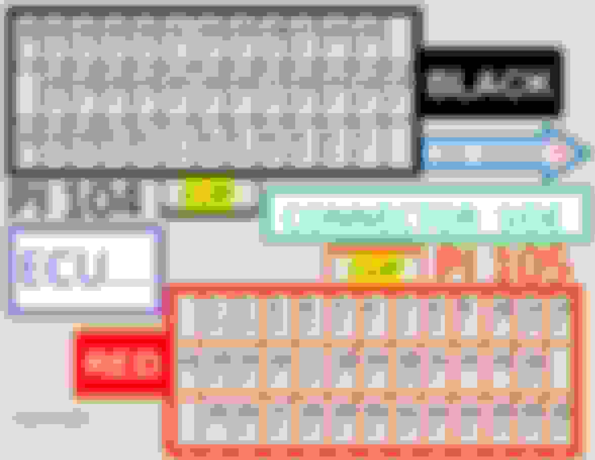
2nd power to the MAF comes from the large ECU Controlled Relay in the form of battery B + voltage ( this power is used at all times )
it is controlled by the ECU and brings power back into the MAF , ECU , fuel injectors , and 4 engine regulation sensors
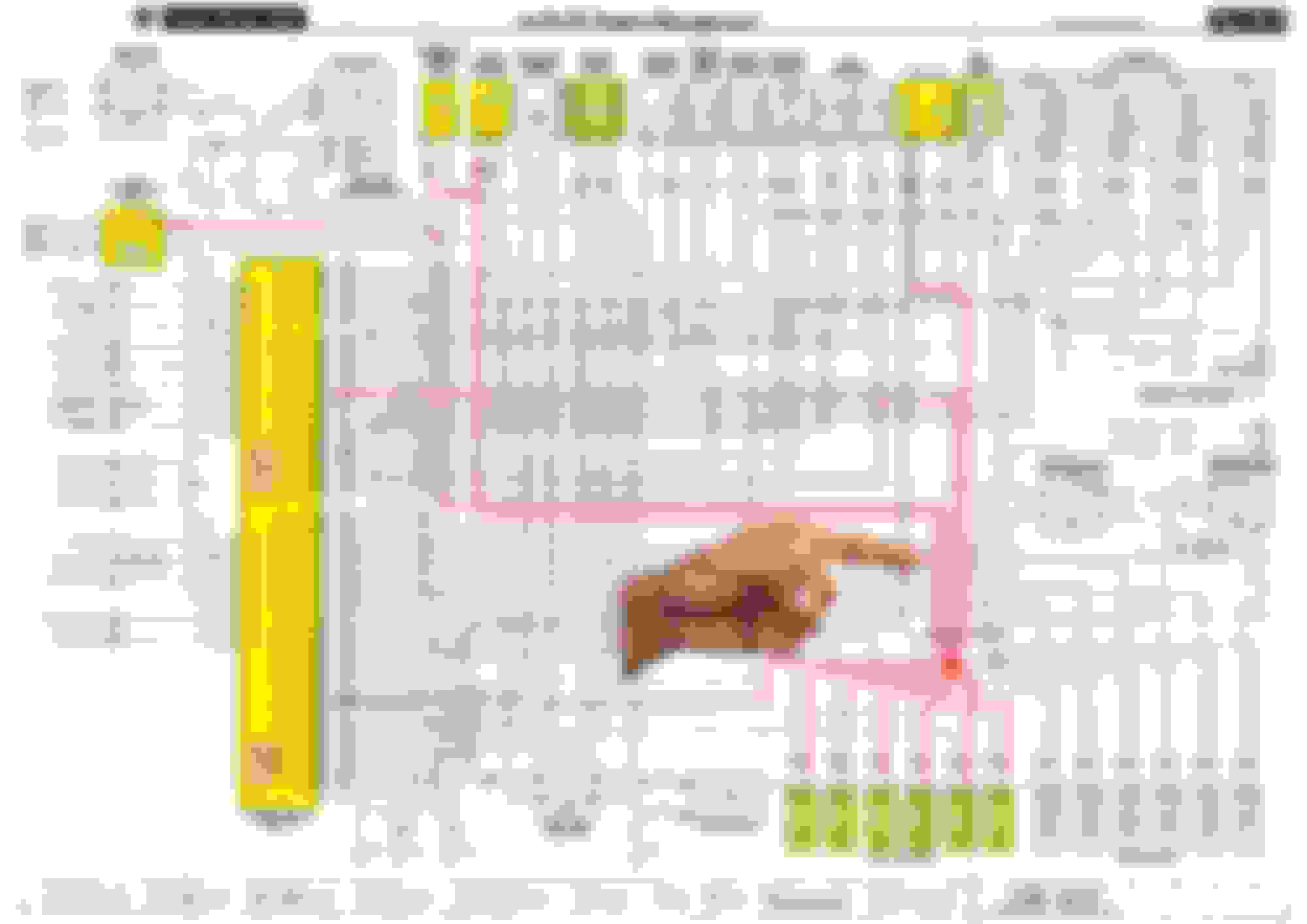
1st power to the ECU is the ignition positive relay in the corner of the right engine bay fuse box ( King Relay ) , this is point 32 double hash circle of the pic below
This will be fuse # 12 / 10 amp in the right engine bay fuse box
in all the fuse boxes fuse # 10 , 12 , 14 , 16 rely on the relay in the corner of the fuse box to close , King relay
all the rest of the fuses are hot at all times and bypass the king relays as wired inside the fuse boxes
instrument power is from a couple of fuses in the left heelboard fuse box ( powered by the closing of the relay in the fuse box referred to as the 2nd ignition positive relay ) ,this is another King relay
To test these King and ECU controlled relays have the key in the run postion and remove them and they should click back to the open , relaxed position
If the relays click they are getting the correct command but the power contacts inside can be burnt and compromised to be able to run their devices properly
"Did you ever get a MAF engine code ?" NO, Only code I've ever gotten is "Random Misfire"
"So your idle is higher than that so 4.5 grams / second" , Came down as eng warmed
I'm trying to read previous wiring diagram you posted but wife moved magnifiying glass,But it looks like wire BLG circuit has control of MAF,EGR, EVAP PLUS INJECTORS ?,,, Would I test that circuit to ground to see iF wires good
Before you run off for a MAF,there are some things to check to ensure you have power on the ECU , MAF , and no CEL light
Editing
2nd power to the MAF comes from the large ECU Controlled Relay in the form of battery B + voltage ( this power is used at all times )
it is controlled by the ECU and brings power back into the MAF , ECU , fuel injectors , and 4 engine regulation sensors
1st power to the ECU is the ignition positive relay in the corner of the right engine bay fuse box ( King Relay ) , this is point 32 double hash circle of the pic below
This will be fuse # 12 / 10 amp in the right engine bay fuse box
in all the fuse boxes fuse # 10 , 12 , 14 , 16 rely on the relay in the corner of the fuse box to close , King relay
all the rest of the fuses are hot at all times and bypass the king relays as wired inside the fuse boxes
instrument power is from a couple of fuses in the left heelboard fuse box ( powered by the closing of the relay in the fuse box referred to as the 2nd ignition positive relay ) ,this is another King relay
To test these King and ECU controlled relays have the key in the run postion and remove them and they should click back to the open , relaxed position
If the relays click they are getting the correct command but the power contacts inside can be burnt and compromised to be able to run their devices properly
Looks like pins 17 & 24 are the ones bringing inputs to the ECM, So I figure my next step is to see if I got power to the ECM on those circuits or do I have broken wire somewhere, But i'm wondering how do I go about doing that
Since you have the fuel injectors working somewhat maybe 100 % , if you put a meter on the 2nd power into the ECU at socket Red 17 and Black 24 you will most likely see B + volts
A compromised connection/ relay power contact will trade voltage for current as a dynamic functioning circuit with power running through the veins
This leaves swapping the large ECU Controlled relay on the premise that the internal power contacts are compromised / burnt limiting the current passing through to your devices like the MAF and others which includes your injectors
If you remove the ECU connectors the ECU Controlled relay will not be able to be commanded closed
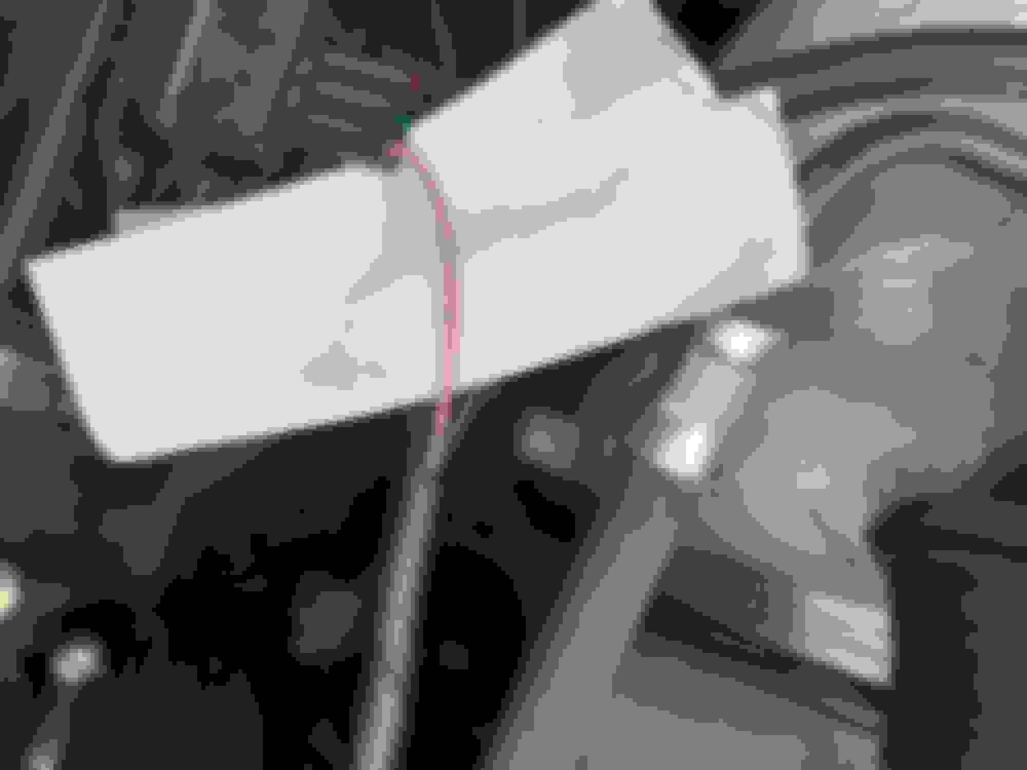
On my ECU Controlled relay socket wires coming out from underneath the wires were nicked as they were messing around with the previous owner
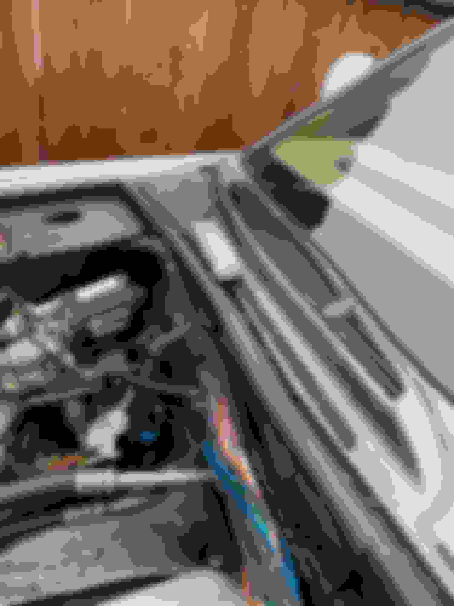
The splice to target would be the one below the pointing finger ( this will be a group of 3 or 4 splices as the wires will not fit in a single splice , this keep the wire bundle thinner and not thick and bulky )
The 2nd splice would be on the EVAP valve under the air filter which may run that OK but not the MAF
Your MAF return signal seems to be in range at 3 volts at 3000 RPM just not seen by the ECU properly
Are you sure the splice for MAF and EVAP are under the air filter , The wires just seem to run off in far different directions
So this wire appears to be the same wire coming off the Maf, Couldn't I scrape off a little insulation and take a reading up on the firewall ? because after that point it looks like the bundle goes thru fire wall to ECM, If I get voltage there then It seems to me the ECM connector would be next to check.

 12-27-2022, 03:12 PM