Cannot reset all sensors
#21
The splices should be up the wire from there under a wrapped-up section
A lot of them are above the fuel rail as the wire bundle runs back
Mine were pristine and clean but saw a pic of someone's that was not
But since you have a signal ( Green / Yellow wire ) coming out of an alive MAF sensor at 3 volts but no signal seen at the ECU I would look at the ECU connector socket Red 4
This signal return wire does not have a splice
Last edited by Parker 7; 01-03-2023 at 04:31 PM.
#22
The splices should be up the wire from there under a wrapped-up section
A lot of them are above the fuel rail as the wire bundle runs back
Mine were pristine and clean but saw a pic of someone's that was not
But since you have a signal ( Green / Yellow wire ) coming out of an alive MAF sensor at 3 volts but no signal seen at the ECU I would look at the ECU connector socket Red 4
This signal return wire does not have a splice
A lot of them are above the fuel rail as the wire bundle runs back
Mine were pristine and clean but saw a pic of someone's that was not
But since you have a signal ( Green / Yellow wire ) coming out of an alive MAF sensor at 3 volts but no signal seen at the ECU I would look at the ECU connector socket Red 4
This signal return wire does not have a splice
Ok thats next, just confirmed I have same voltage up top
#23
Something I remember from Vee was his suggestion of giving the pins / blades on the MAF connection a bit of a twist to get them to better connect with the sockets
You have the same blade type of pins on the ECU connector and on the sockets side there are 2 pinching tabs that some of the tabs can be missing
You have the same blade type of pins on the ECU connector and on the sockets side there are 2 pinching tabs that some of the tabs can be missing
Last edited by Parker 7; 01-03-2023 at 05:13 PM.
#24
#25
#26
#27
Leaving alone the ground wire of the 3 wires in the MAF circuit..........
Use as small of a paper clip to not spring apart the sockets
ECU connector : Red 4 to Black 24
MAF connector : Green / Pink to Black / Light Green
The Pink / Slate wire in your pic is the ground wire in the 3 wire circuit , colors change a bit with aging
Water can get into the ECU connectors as the wire goes into the connector , they have a rubber seal on each wire , but water can climg to the wires coming down from above and pass through the seals and effect the crimp between the socket and the wire , give the wire a slight tug
These individual wire seals where missing on mine
..
Last edited by Parker 7; 01-03-2023 at 06:42 PM.
#30
#32
Ok, I'm assuming this was supposed to be with key off.
"Unplug the ECU connectors and jumper the Red 4 to Black 24
With your meter on the MAF connector sockets with the wire colors Green / Pink and BlacK / Light Green check for resistance and should be close to 0 "
Black to Green = 0.00
Black to Pink = 0L
Green to Pink = 0L
"Unplug the ECU connectors and jumper the Red 4 to Black 24
With your meter on the MAF connector sockets with the wire colors Green / Pink and BlacK / Light Green check for resistance and should be close to 0 "
Black to Green = 0.00
Black to Pink = 0L
Green to Pink = 0L
#33
Ok, I'm assuming this was supposed to be with key off.
"Unplug the ECU connectors and jumper the Red 4 to Black 24
With your meter on the MAF connector sockets with the wire colors Green / Pink and BlacK / Light Green check for resistance and should be close to 0 "
Black to Green = 0.00
Black to Pink = 0L
Green to Pink = 0L
"Unplug the ECU connectors and jumper the Red 4 to Black 24
With your meter on the MAF connector sockets with the wire colors Green / Pink and BlacK / Light Green check for resistance and should be close to 0 "
Black to Green = 0.00
Black to Pink = 0L
Green to Pink = 0L
Last edited by sturner; 01-06-2023 at 02:40 PM.
#35
I was the R & E with the 4 color markers in his pocket on the flight line between flights
We only had 1 / 747 flight though our hub going to Hawaii nonstop
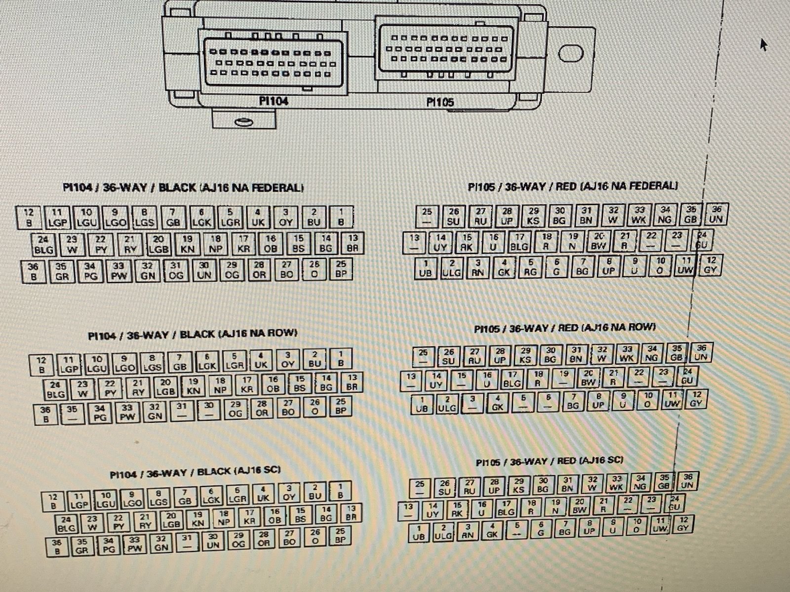
The pic you have is looking down into the ECU connectors on the ECU side so it is a mirror image of the chart I made of the wire side half with the wonderful colors
My pic is also of the connector face and not the wire protruding
looking down into the ECU connector it won't be powered up so there is nothing to look at except the condition of the pins / blades
the Red 4 ( PI05 -4 ) pin will be receiving the 1.2 volts DC at idle as the MAF return signal
The Black 24 will be receiving B + raw power from the ECU controlled relay into the ECU , so it is just a test point using the Black / Light Green wire
Normally the other engine sensors are feed by the ECU a precise 5.0 volt DC reference power from the ECU but not in the MAF case
But it does provide a meter test path in that you're looking at the integrity of the Green / Pink MAF return wire at Red 4
Ask questions
Last edited by Parker 7; 01-06-2023 at 09:46 PM.
#36
Ok I'm still confused, On the diagram with the red line you highlighted circuits BLG, I was assuming I was jumping those 2 circuits , I jumped red 4 to black 24 & check resistance at the MAF, But according to the diagram I up loaded the BLG circuit is actually red 17 & black 24, What am missing ? Thank you
The following users liked this post:
Parker 7 (01-07-2023)
#37
Ok I'm still confused, On the diagram with the red line you highlighted circuits BLG, I was assuming I was jumping those 2 circuits , I jumped red 4 to black 24 & check resistance at the MAF, But according to the diagram I up loaded the BLG circuit is actually red 17 & black 24, What am missing ? Thank you
#38
#40


