When you click on links to various merchants on this site and make a purchase, this can result in this site earning a commission. Affiliate programs and affiliations include, but are not limited to, the eBay Partner Network.
But I'm not sure the engine is staying in open loop , he may have a reader / device that is giving flip flopping numbers on his ECT like the TPS
One of those cheap inferred temp sensors pointing at the thermostat housing in a unpainted area would give the regulated coolant temp
He may not even have a fuel tank vapor pressure pressure switch / sensor , I think it depends on if he has a 1 or 2 vapor canister version of the EVAP system in the 801S document
Someone had a IAC test / reset procedure if I recall correctly
Otherwise, the step motor wiring looks in this form and a fault may not show until the step motor is warmed up and tapping on it , this is another application of a old school needle meter you can see wiggle
So that's a can of worms to go down that avenue
So you can have a open on one of the winding legs and there are 9 meter lead combinations, this could keep the IAC valve from scheduling down to the close to closed position and hang up in a too open position
I'm german and its sometimes difficult to understand what you say, but I try. Thanks for the additional informations.
I've driven some cars in my 30 years of driving but I never experienced so much help, patience and kind people in a car forum like here (also other Jaguar forums). I would truly miss my cat but also you guys.
Parker,
I don't disagree, that the OBD2 reader might be misprogrammed, or looking at the wrong PID for the TPS value. The TPS numbers just don't make sense. In the same vein, I've never had a device that would tell me why my car was stuck in open loop, so I'm kind of ignoring that information because I can't believe there's a device out there that could do that, accurately. My PDU and WDS won't do that for me!
I think the temp values he is seeing make sense, and if that's what he's reading at the OBD2 port, I have to assume that's what the ECU is seeing too. I'm crossing off temperature. I mean, I don't see how even a failed thermostat can cause these problems if the CTS is reading coolant temps in the necessary range? (Checking it wouldn't hurt though)
Why are you hung up on the IACV? He says his idle is fine, and that's not a sensor that affects open/closed loop. I'm interested in why you think that sensor is in play?
The IACV reset is only temporary on the AJ16 engines. It will be "reset" only until the car is turned off, then it will revert to whatever it was doing before. I don't see how it is relevant, but here it is:
Run engine until you reach normal operating temperature.
Switch ignition off.
Switch ignition on, wait 5 seconds, then disconnect the connector to the idle speed controller.
Switch ignition off.
Wait 15 seconds then reconnect idle speed controller.
Repeat two more times.
On last repeat, do not reconnect idle speed controller.
Start the engine.
Check the base idle speed, which should be at 550-600rpm.
I believe the pins on the ECU need to be checked for corrosion, and the TPS might need to be replaced.
Why are you
Originally Posted by Parker 7
I agree with what Vee said in post # 100
But I'm not sure the engine is staying in open loop , he may have a reader / device that is giving flip flopping numbers on his ECT like the TPS
One of those cheap inferred temp sensors pointing at the thermostat housing in a unpainted area would give the regulated coolant temp
He may not even have a fuel tank vapor pressure pressure switch / sensor , I think it depends on if he has a 1 or 2 vapor canister version of the EVAP system in the 801S document
Someone had a IAC test / reset procedure if I recall correctly
Otherwise, the step motor wiring looks in this form and a fault may not show until the step motor is warmed up and tapping on it , this is another application of a old school needle meter you can see wiggle
So that's a can of worms to go down that avenue
So you can have a open on one of the winding legs and there are 9 meter lead combinations, this could keep the IAC valve from scheduling down to the close to closed position and hang up in a too open position
I will have a look at the ECU and I hope that I will get it out without breaking a Pin or anything else. Haven't found a good DIY to do this. One guy stated, that there is a plastic thingy above the connectors, which need to be cut with a dremel. oh my god,
Its the love to the car. Any other car would be gone long time ago. But not my cat.
edit: found this regarding the drive cycle for the 308. is this the same for the x300? sometimes its stated, that the AC has to be off during the drive, but not the heater and so on.
2. Idle The engine must be run for two and a half minutes with the air conditioner and heated rear screen ON. The heavier electrical load the better as this will test the O2 Heater, Passive Air, Purge "No Flow", Misfire and (if closed loop is achieved) Fuel Trim.
Last edited by Slazenger7; 09-15-2022 at 08:08 AM.
I will have a look at the ECU and I hope that I will get it out without breaking a Pin or anything else. Haven't found a good DIY to do this. One guy stated, that there is a plastic thingy above the connectors, which need to be cut with a dremel. oh my god,
Its the love to the car. Any other car would be gone long time ago. But not my cat.
No! That�s probably what you might need to do if you find corroded pins that need to be replaced. All you need to do is get to the ECU, unbolt it from the car with a 10mm deep
socket, then unplug the black and red plugs, then look inside for any hint of green. Then lightly touch the pins to see if any seem loose.
Funny thing about your car is that a replacement ECU is cheaper than a new TPS! I'm wondering if you shouldn't find one to test from eBay. LNA1410, or LNB1410....not sure which for sure.
Don't forget the dedicated ECU external case ground strap on the ECU
You don't need to drimal or destroy the ECU connectors
The fault with the ECU sockets from my understanding is water migrating along the wires from the top down
The area of concern is the hidden from view the crimp on the wire to the socket just below the wire waterproof seals , this will give you high resistance on the individual wire run
One test is to slightly pull on the suspect wire and see if it comes off the socket , but then you will be left with a totally broken wire and lose what you have and put you in a corner
eventually the corrosion will migrate to the ECU pin area where you can visually see it
So a non - destructive test would be to check for resistance on the wire individual run without tugging on the wire at the ECU connector
The ECU sockets have 2 tabs that pinch the pins /. blades on the ECU side . I had / have 5 missing tabs
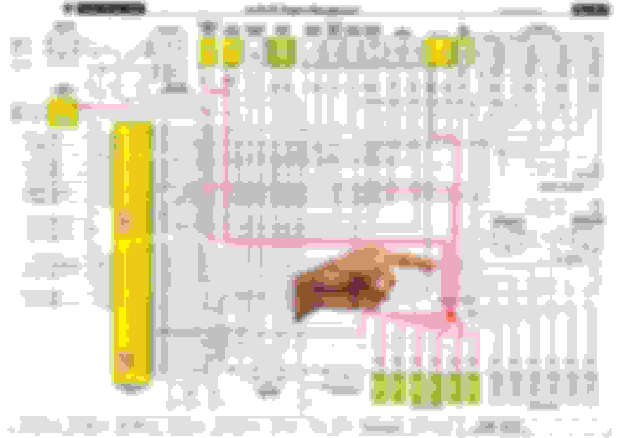
When I tested the wire runs on my engine I selected a section of the wiring diagram and had a big print made at the office supply / print shop from a flash drive and has to be the format they except , in this case a JPEG image
This is an image for the supercharged version but is the same for your 4.0 normally aspirated , just negate some items like the 2nd fuel pump , EGR and such
You can just put a check mark on the wires testing OK and be better able to keep track of your work
the - 2 TPS connector position for the Green / Yellow return wire to the ECU will be the center wire on the TPS connector
Vee , you had a suggestion on giving a slight twist on the sensor pins / blades to make better contact with the sockets but I think that pertained to the MAF sensor ( which is another value that is not consistent with this example )
Note that this print does not show the fuel tank vapor pressure sensor which is tied into the TPS ( but it might not be the case with his EVAP fuel tank configuration with 1 or 2 vapor canisters )

 09-14-2022, 04:40 PM