Gauges not working
#21
#22
#23
It is strange as it seems that my last post is not here.
Unfortunately I received the wrong ignition switch. The seller agree that he made a mistake and the correct switch should arrive on Monday.
I am super thrilled that I found where my parasitic drain was coming from--the ignition relay in the left heel board was staying on. I do have a concern however. I bypassed the relay completely by providing a ground to the n.o. side of the relay switch. I still do not have 12v to the ignition fuses in the fuse box. This concerns me greatly. Of course a ground can't provide +12v to the fuses so there is something going on between the relay and the fuses. Does anyone have an idea what I should be looking for?
Thanks,
Jomo
#24
The relay has 2 halves that are electrically isolated from each other
The control half should always have 12 v control power " sitting " and always present on the Brown colored heavy wire from battery ( hot at all times )
To close the relay the White / Yellow colored wire is seeking a ground path to car frame
This ground path goes through the ignition switch through pin 3 to pin 5 which is the dedicated ground path to car frame
Between the relay and ignition switch connector the control ground wire ( White / Yellow ) it must pass through a closed inertia switch
With the ignition switch connector removed the relay should still be relaxed and open . If not the White / Yellow colored wire between the relay and the ignition switch connector has a car frame ground not desired
The fuse box is hard wired between the relay power contacts sockets and the large terminal post and to the dedicated fuse positions of 10 ,12 , 14 , 16 ,
The connectors on the back side of the fuse box should have nothing to do with your observations
But the same 10 , 12 , 14 , 16 configuration is the same for all fuse boxes so the left engine bay fuse box is a swapping option since the relay attached to it in reality only runs the horn
The small set screws on the ignition switch are slots that are cut with a thick cut and not thin cut , this may explain the blade screw clicking around when using as the blade width may be a bit to small
Last edited by Parker 2; 06-26-2021 at 01:02 PM.
#25

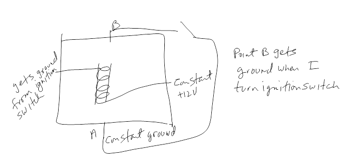
I am getting the impression that I am no explaining things well. That is why I posted the above diagram.
My main concern is whether or not point A of the ignition relay in the left heel board should have a constant ground or not.
If it should have a constant ground then how does the wire from point B, which obviously is also a ground become +12v to supply 12v to the fuses? I suspect that there is another relay that turns that ground into 12v. Or maybe point A should not be a constant ground?
The ignition switch did not arrive today. I am hoping that it arrives tomorrow.
Thread
Thread Starter
Forum
Replies
Last Post
Currently Active Users Viewing This Thread: 1 (0 members and 1 guests)


