When you click on links to various merchants on this site and make a purchase, this can result in this site earning a commission. Affiliate programs and affiliations include, but are not limited to, the eBay Partner Network.
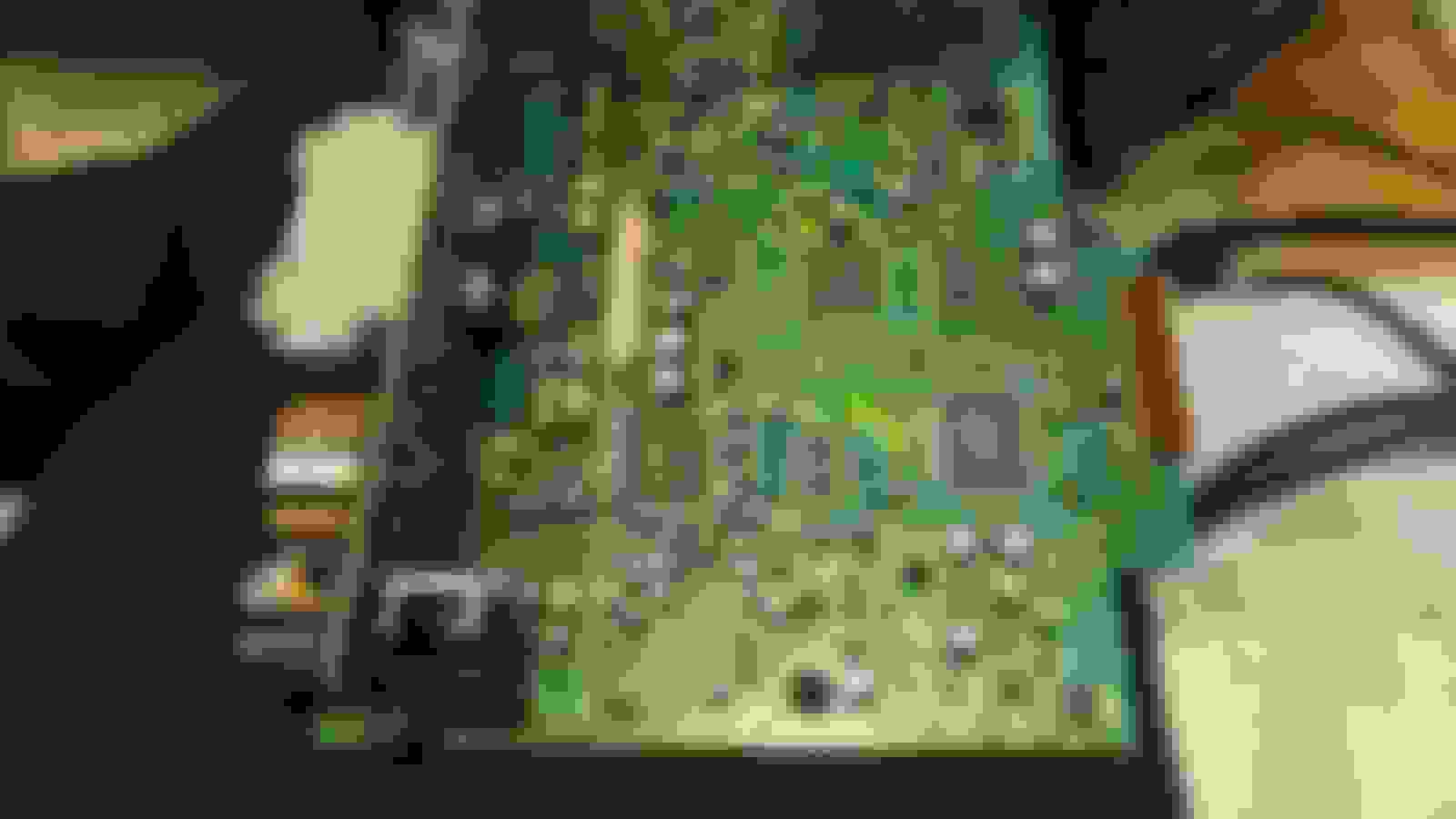
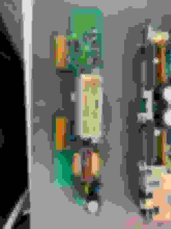
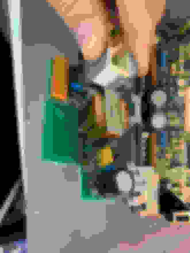
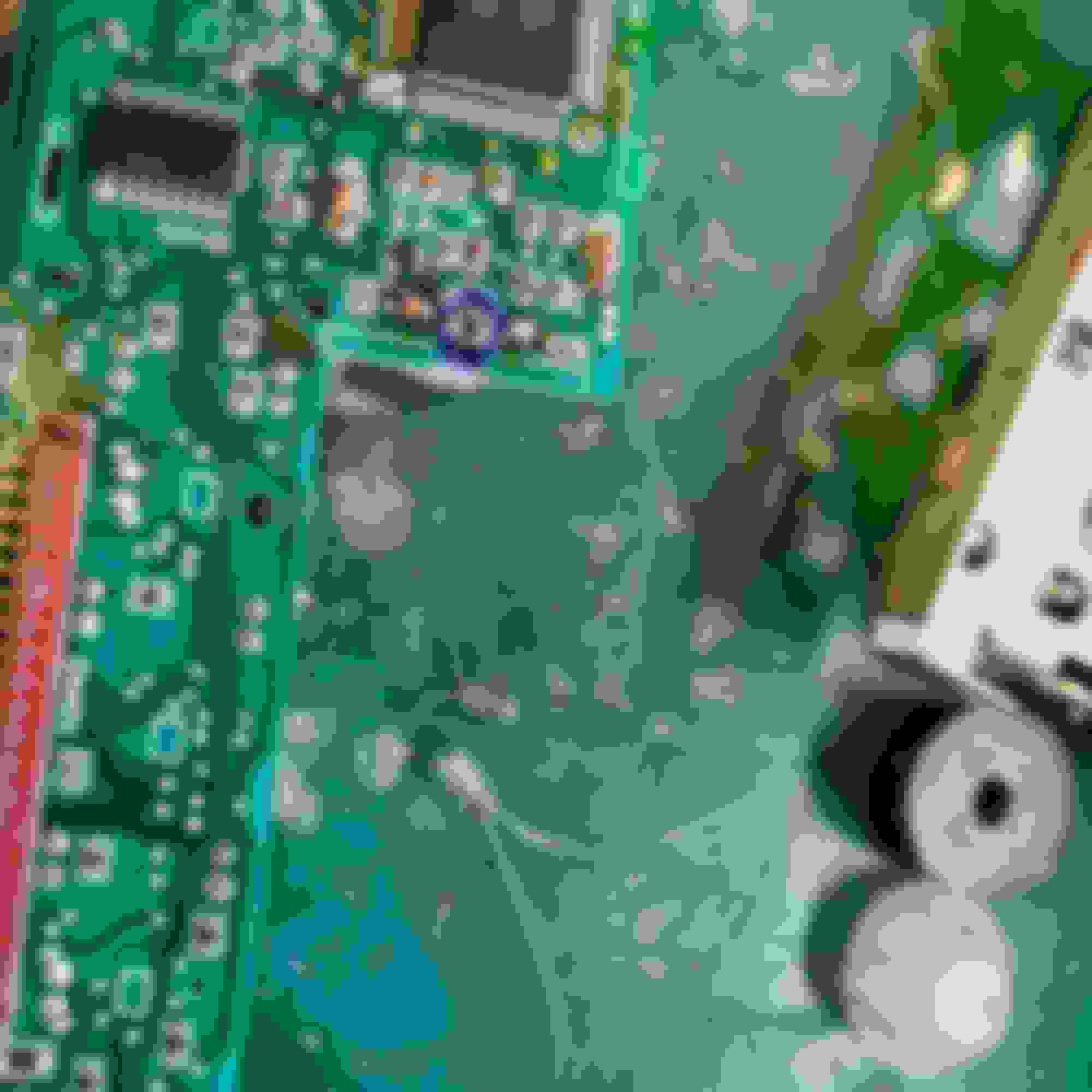
Replaced my LWB X300 with a much better SWB in the same colour recently and new car came with original Alpine radio which I've decided to keep. None of the backlight bulbs lit up though hence needed to open it up, also had to replace a slighty leaky screen. If anyone gets this fault, you'll have to replace a 7.5 ohm resistor in the back corner as per pics below.
I didn't have a 7.5 ohm resistor though so replaced it with half that but much higher wattage. The only other resistor I had at the time was 80 ohm and that didn't work. All lights work fine now.
Disassembly is generally easy, you will need to remove board off the bottom metal plate though and its secured with small metal prongs and one is also soldered so a desoldering wick and soldering iron is needed. Front panel is held by 4 screws, two on the sides and two that hold it to the cassette drive.
The only thing to remember is that there are at least TWO AJ9500R revisions and one doesn't have that resistor but two SMD ones on the other side of the board.
Hi katar83, thanks for your detailed description of the alpine Aj9500 repair. You mention a leaky screen which i�m also suffering badly on similar unit in my xk8. Were you actually able to repair this, if so can i ask where you sourced compinents?
many thanks
dave
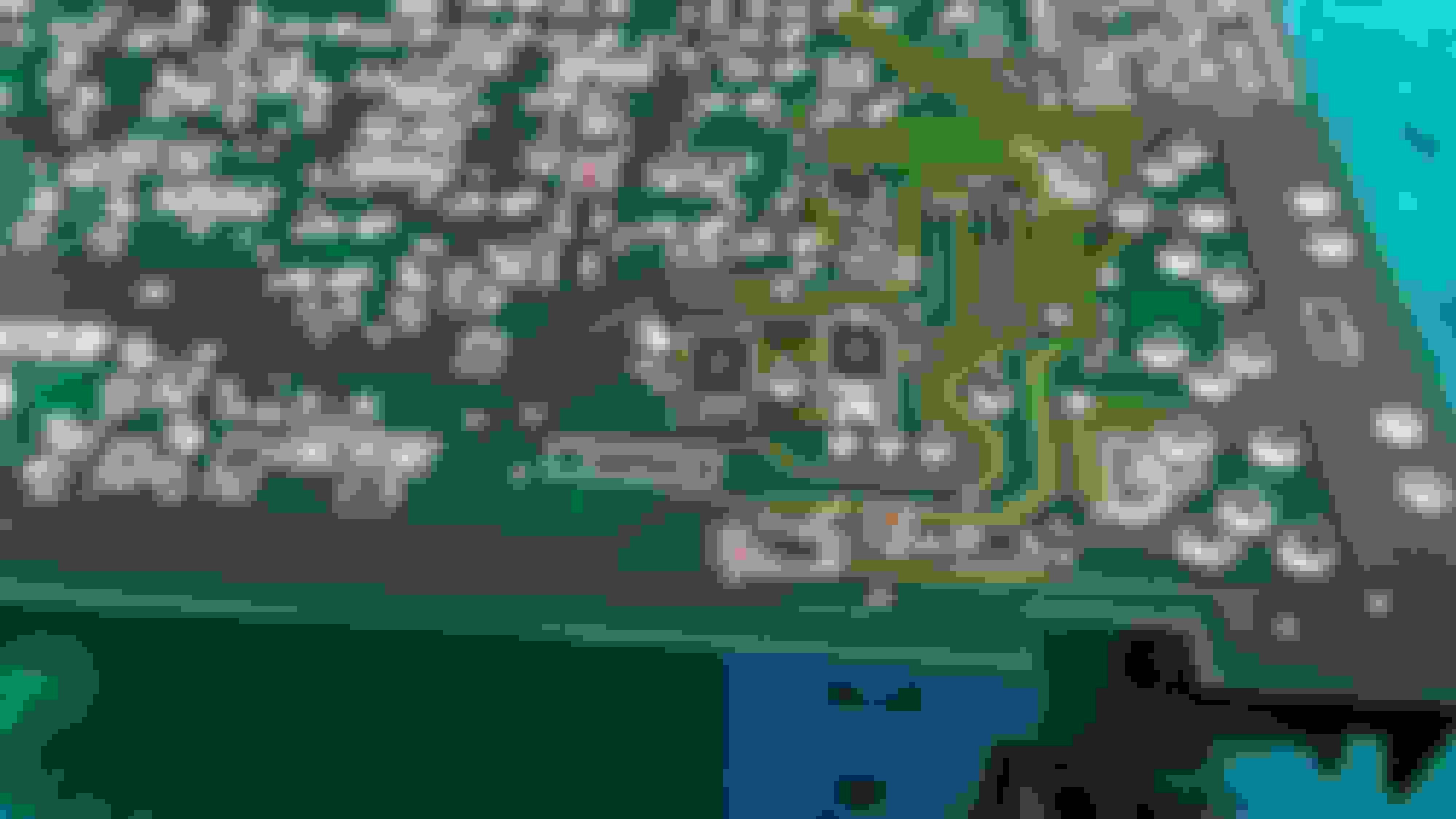
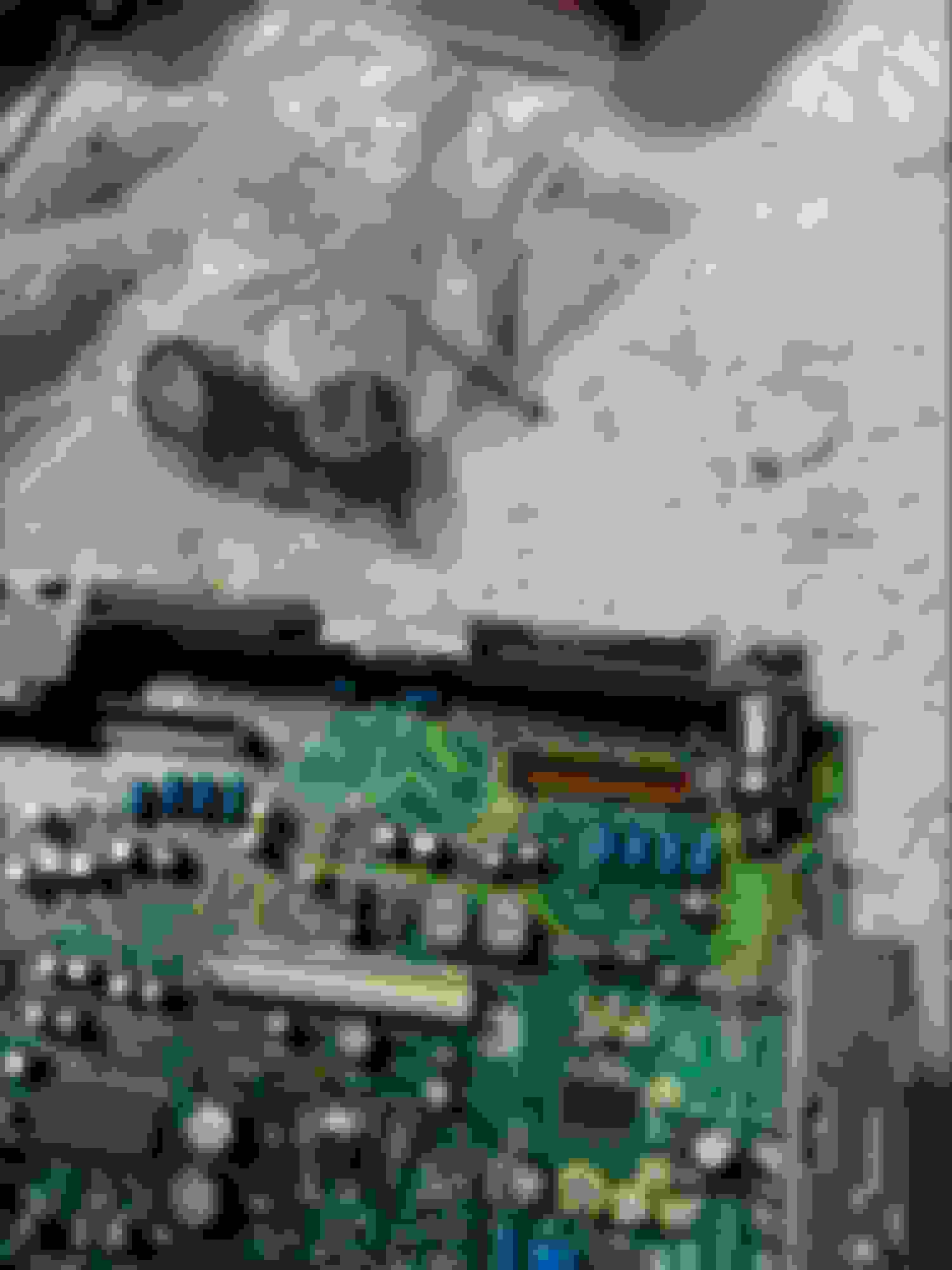
Yep they are the two large SMD resistors marked 150 that come off the emitter from the transistor. One of mine was bad as I was measuring 15 ohms and two resistors in parallel should measure 7.5
Last edited by John Baker; 07-22-2020 at 03:28 PM.
Hi Katar - where do you source replacement LCD screens for these units? If possible, can you also advise on a source for replacement clock LCDs/ribbons?
I finally opened up my unit and discovered what looks like heat damage to the two SMD 150 resistors. However I was able to measure 7.5 ohms at all points from the center post of the transistor, past the resistors and all the way along the trace to the VDD pad for the display illumination.
For fear of doing more harm than good, I didn't touch anything with the iron. Unfortunately I still have no LCD illumination! I suppose the weakened connections can't carry enough current for the lighting. Or maybe there's a totally different issue.
You can see the spot where the large 7.5 ohm resistor would go on later units, although relocating it there didn't fully solve the burnout issue.
It seems the heat from that transistor is too much for the surrounding components. On the other side of the board in this area, is the small component that causes the NOT CONT failure with the CD changer. I'd bet it desolders itself over time. The transistor's heat sink isn't big enough.
The two 15 ohm resistors are likely failing under a load if your seeing 7.5 ohms but no backlight. The resistors are the weak point of the circuit and very likely your failure point. I replaced mine with two 1 watt 15 ohms and so far everything has been working fine. I suppose you could use a singe 2 watt 7.5 ohm resistor but your gonna have a space issue with the resistor pressing against the bottom of the metal housing. Also you could replace with new SMD resistors to keep it flat but I didn�t want to special order this and use hot air on the board.
Last edited by John Baker; 11-01-2020 at 02:35 AM.
Hi Katar - where do you source replacement LCD screens for these units? If possible, can you also advise on a source for replacement clock LCDs/ribbons?
Thank you!
No replacement LCD screens for these as far as I know, I do have a few spare radios though so that's where I got my spare screen from. LCDs and ribbons for the clock though can be purchased directly from SACER. Can highly recommend them, they supply both and service is great.
By the way, great idea John, wasn't sure that a normal resistor could fit in there, in place of these SMD ones but your pic definitely proves that you can
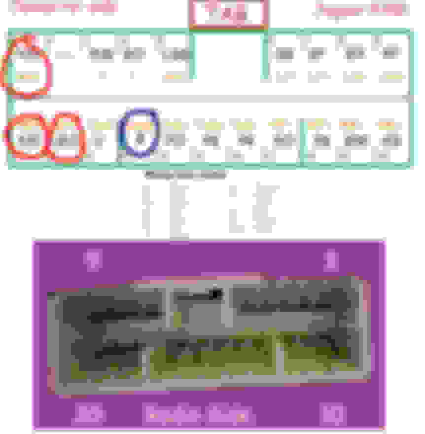
Hi again,. I found pinout of this radio finally and power up radio but no work. My board is a bit diferent than yours. I check resistors and they are ok and solders too. Radio doesnt power on. Can anyone help me with the repair or any tip please?
On the photo of pinout I mark pins and use to power up. I think they are ok.
thanks a lot in advance
A no power repair could be so many different things. I could throw some ideas out there but don’t want to lead you down the wrong path. If you want send it to me with return postage and I’ll give it a go. I’m in Texas.
A no power repair could be so many different things. I could throw some ideas out there but don�t want to lead you down the wrong path. If you want send it to me with return postage and I�ll give it a go. I�m in Texas.
Hi mate,
I send to you message. Please let me know.
thanks
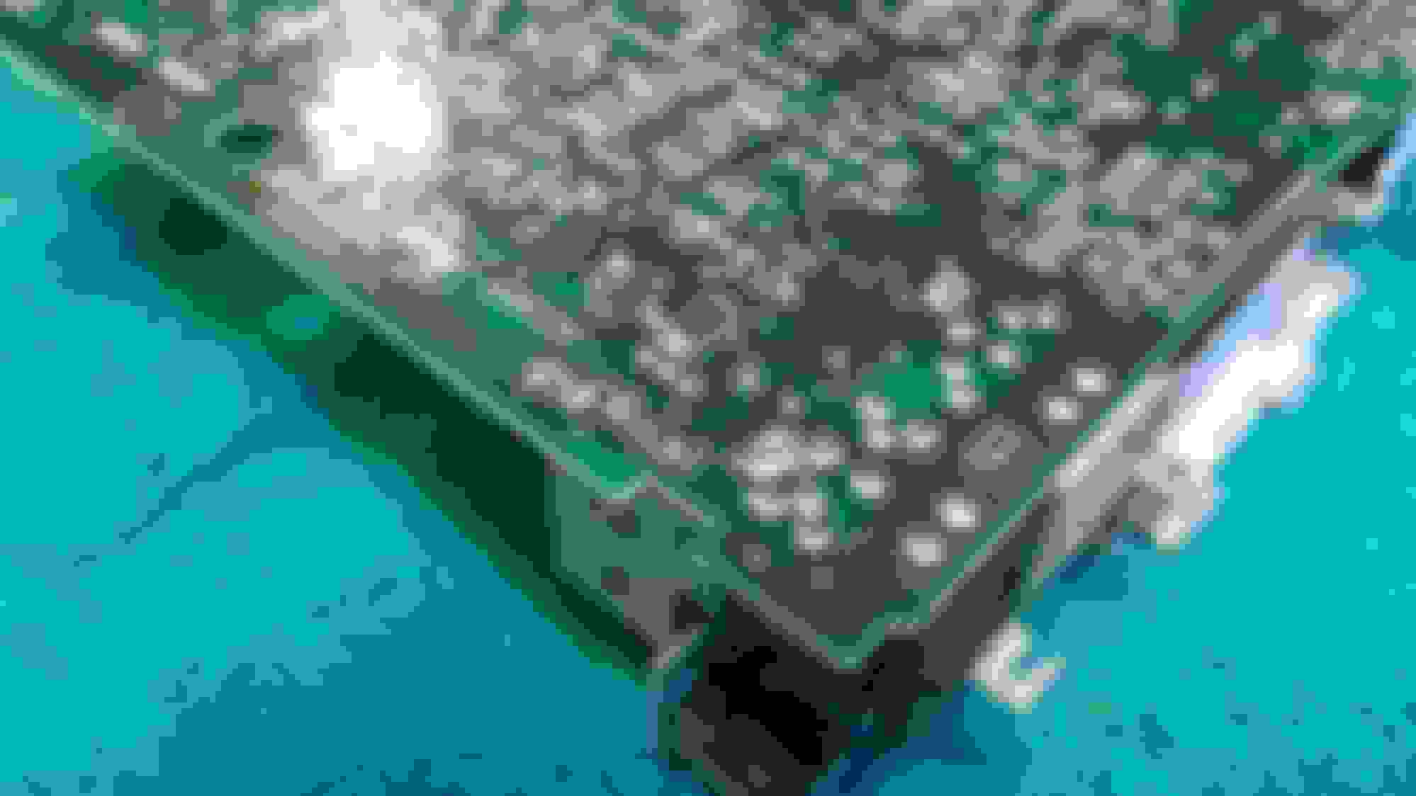
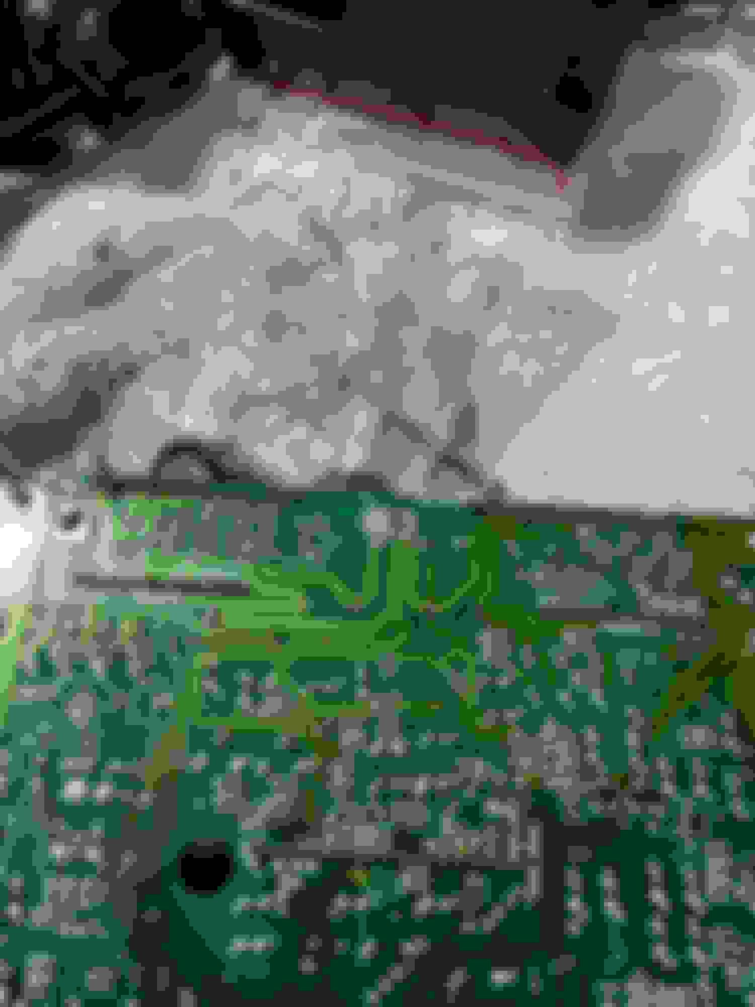
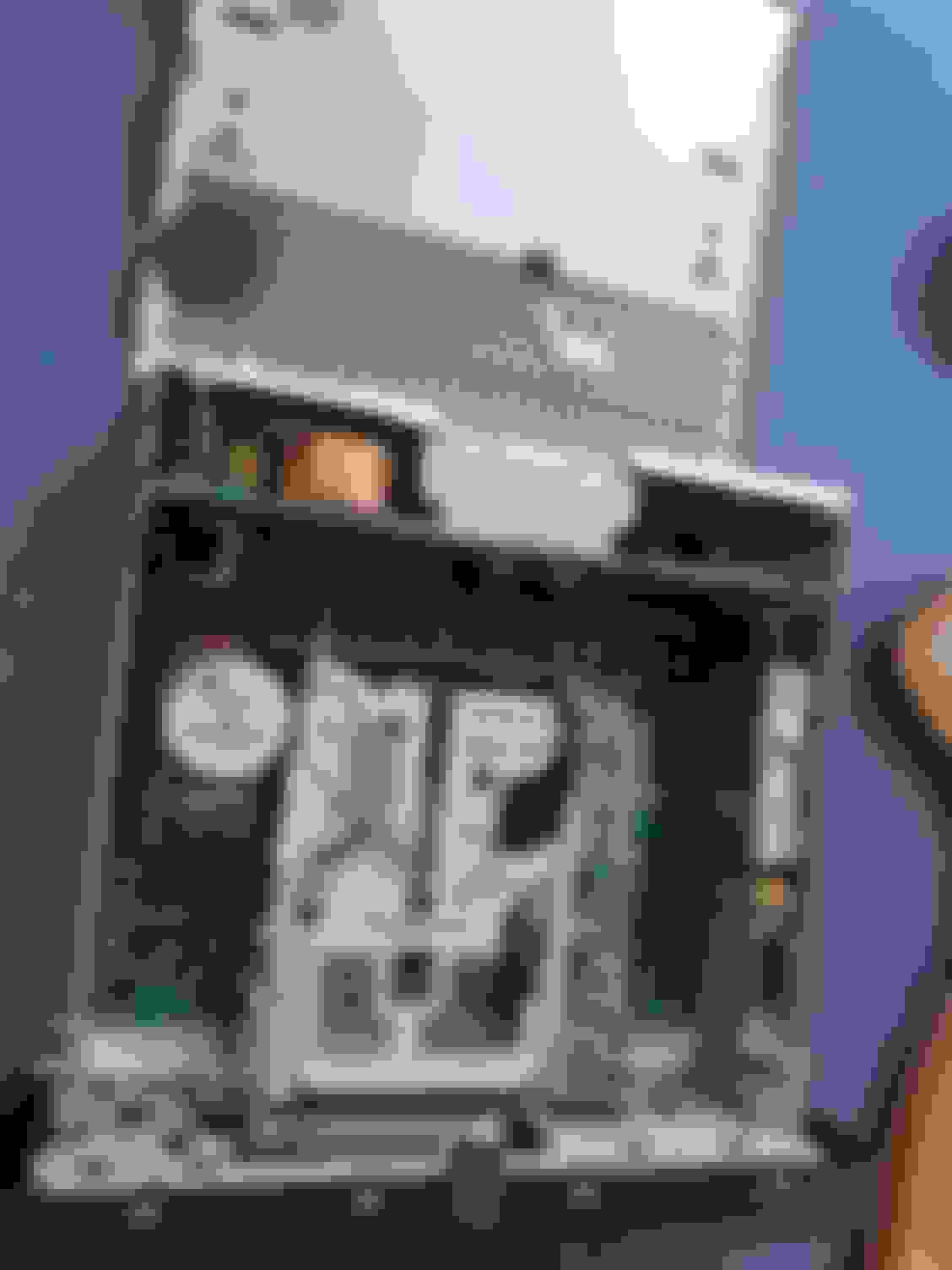
Check the black electrolytics next to the audio amps. All of mine were bad, and a few of the smaller 10uF ones were leaking and caused trace damage that need to be repaired. In the photos below I have sanded down the PCB a bit to check them and get any remaining acid off the board. You will know if this is an issue as soon as you start to desolder them you smell dead fish. I almost think thats a better test than the cap tester lol. I couldn't find any of the other caps bad. Also check for shorts on the amps as I could see these failing to the point they take them out too. Its a bad design. With that smaller top power board in place all the heat is trapped in there and just bakes those caps, reducing their life tremendously. The larger 2200uF caps also showed bad ESR. Best to just replace all 12 with quality 105C Nichicon from somewhere like mouser or digikey. I'm going to try to leave the leads long and place the new ones as far as I can from the audio amps.
New ones are not cheap : https://www.ebay.com/itm/281973079129 Mine seem to be good according to the scope, though they did need to be resoldered as they were developing the ring cracks.
Also if you have a wonky volume encoder like most do, they can be opened up by releasing the cleats on the sides so the top comes off, then clean the tabs and top round thingy off real good and carefully bend the tabs up so they make better contact. An erasure from a pencil works nicely on the top round part. Then put it back and bend those cleats back into place.
Last edited by John Baker; 05-21-2022 at 01:18 PM.
Had another issue with backlight on my AJ9500R, this time the bulb gave up. Repair is quite involved as it requires removing and disassembling the radio, with the top panel gone and the tape drive removed it is possible to remove the front panel from the radio. This then splits into two and then after desoldering two metal pads the pcb with the screen and bulbs can be removed. Desoldering the screen bulb is easy and the screen does not have to come off(initially it looks like it might). Original bulb is abour 2mm wide and 5mm long, I only had slightly bigger ones but that still just about fitted in the bulb holder.
Had to replace the screen too as it leaked in right bottom corner but luckily had another front panel with half the parts missing but perfect screen so swapped that over, reassembled the radio and now it works perfect again!
It is quite an involved repair, easy if you ever used soldering iron but easily taken me 3 hours.
Hope it helps someone!
Hi, thanks for posting this - very interesting. Just acquired an XK with dead AJ9600R and opened it up find this resistor burnt out. I didn�t really investigate signs of life other than the complete absence of lights. Though it is obviously (catastrophically) burnt, I was reluctant to replace it in case the root cause was a shorted cap, etc, which sent me down the Google worm hole (I presumed it was on supply side rather than just lighting) What wattage should this resistor be? Do you happen to have a circuit diagram or other info about this unit?
Originally Posted by katar83
Replaced my LWB X300 with a much better SWB in the same colour recently and new car came with original Alpine radio which I've decided to keep. None of the backlight bulbs lit up though hence needed to open it up, also had to replace a slighty leaky screen. If anyone gets this fault, you'll have to replace a 7.5 ohm resistor in the back corner as per pics below.
I didn't have a 7.5 ohm resistor though so replaced it with half that but much higher wattage. The only other resistor I had at the time was 80 ohm and that didn't work. All lights work fine now.
Disassembly is generally easy, you will need to remove board off the bottom metal plate though and its secured with small metal prongs and one is also soldered so a desoldering wick and soldering iron is needed. Front panel is held by 4 screws, two on the sides and two that hold it to the cassette drive.
The only thing to remember is that there are at least TWO AJ9500R revisions and one doesn't have that resistor but two SMD ones on the other side of the board.
There's no circuit diagram for this radio and you can fit any resistor size that will fit in there, think the one I did was 3W so quite chunky but still fitted ok. 2W will be absolutely fine too. If the radio is dead completely and nothing shows on screen then you'll have to look into replacing a number of electrolytics on that board too. You'd need an ESR meter for that and a good soldering iron as a minimum.
Thank you. I plugged it back in but it is totally dead. It was mentioned above that the row of black caps under the slide in board are likely culprits - would these prevent it from switching off or are they more for the amplification side?
Thanks for posting this. I finally got around to pulling my radio. The no backlight issue was annoying. At first I didn't thoroughly read the thread so I missed the part about two versions. I was looking for the surface mounted resistors but mine has the axial resistor. It showed a burn spot like in the above picture. I have an old school electronics supply place near by and all they had for 7.5 ohm resistor was a .5 watt so that's what I put in. It fixed the problem. Now hopefully it stays fixed.
Has anyone had an issue with just the CD/Tape button not working. My tape player works fine, and the CD exchanger loads fine but when I press the button to flip to CD it does nothing. The only thing I have checked is the switch has continuity when I press it. Otherwise I'm not sure what I could check next. Any insights/thoughts would be be appreciated.
Has anyone had an issue with just the CD/Tape button not working.
Yes. I never tested my changer before removing it, but the A2D-JAG97 I put in its place worked most of the time for a while, until NOT CONT was always presented when hitting the CD button. Now the button has no response, and I have to use a Bluetooth FM modulator or tape adapter. Maybe the head unit will only check a certain number of times for a response from the changer before assuming it was deleted.
 02-22-2020, 10:34 AM