When you click on links to various merchants on this site and make a purchase, this can result in this site earning a commission. Affiliate programs and affiliations include, but are not limited to, the eBay Partner Network.
So in light of no available sunroof parts for my 1997 XJ6 I am in the process of modeling, and 3D printing/CNC these two parts, they are thr typical ones that bust up there. I should have both sides available at some point in the near future. Once i have proof of concept, and printed tests for fitment. I'll send the metal bit out to a CNC shop and see what they can do. If it all works, I could get more made, if anyone is interested... Don't now the price yet but so far I'm about $3500 deep down the English rabbit hole on the project.. haha
Welcome to the Jaguar Forums! It's great to have you with us.
$3,500.00 will go a long way toward purchasing a good driver-quality X300, so I can't say you're likely to recoup your investment anytime soon. I'll give you some grace for now and treat your posts as reports on a DIY project, but if you get to a point where you want to offer parts for sale, those posts must be made in the Marketplace, not in the Model forums.
Please visit the New Member Area - Intro a MUST and post a required introduction so we can learn something about you and your Jaguar and give you a proper welcome.
Cheers,
Don
Ha, thanks Don, rookie move. Read up on what's up. No plans to recover costs but the new 3D printer is gonna come in handy for lots of small jag bits in terms of the modeling, it was more of an is it possible, seeing as both my 96 and my 97 XJ's need em. And I head grumbling locally about access to repair parts, as I took out my headliner and just got it re- done in tweed. Fellow at the apholstry shop said they get them in now and again with folks fooking for bits.
Will keep posts on the straight and narrow!
Here is definitely the place to write about making these parts as people (me) don't look at market place to find parts that they know are not available!
You need to gauge interest. In fact there is a post just now from someone who's sunroof had jammed in tilt so you could have your first customer!
Take a leaf out of XJREngineer and write about what you are making (tick), when they maybe available (tick) but DON'T mention price (tick). In fact what did he do wrong Don?
Here is definitely the place to write about making these parts as people (me) don't look at market place to find parts that they know are not available!
Hi Pete,
The forum rules expressly state that For Sale, Wanted To Buy or Wanted To Trade posts are to be made in the Marketplace, not in the Model forums. See this announcement which is at the top of every model forum:
So in light of no available sunroof parts for my 1997 XJ6 I am in the process of modeling, and 3D printing/CNC these two parts ...... If it all works, I could get more made, if anyone is interested... Don't now the price yet but so far I'm about $3500 deep down the English rabbit hole on the project.. haha
I was going to send this to you as a PM (Private Message) but, as Don B has already had to intervene, a post in the thread is more appropriate. It is not intended as a public rebuke but simply so that everyone reading the thread understands how advertising on the forum works. It will prevent the thread becoming a thinly disguised advertisement and then either closed or removed.
I have no wish to discourage development of replacements for unavailable plastic parts or the posting of information on these BUT there are rules on advertising parts for sale on the forums. Seeking "expressions of interest" crosses the line.
If you get to the point of being able to offer these parts to other members, please contact me first to discuss an appropriate method of listing. We already have a few talented members who have developed replacement parts or upgrades and there is a right way to promote these without upsetting our forum Sponsors and Vendors who pay for the privilege of advertising their parts and services.
Roger that Graham, More excited to let people know something is in the works to save wet shoulders. Obviously a dark rabbit hole to even consider going to these lengths, at a cost for more than you can buy a whole car, but I just couldn't help it. Appropriate to post pictures of developments as they continue on the project? maybe just worth it to delete the post completely, and I can start a DIY garage fix post instead. And if / when anything comes to fruition I will look for direction from you on what's allowed. Don't want to push against the government red tape as it were
So anyone interested in the DIY Jag project... Some solid developments in the area. With the help of a local 3D modeling and printing company "Replik8", I was able to get some proof of concept models on the ground to test out in the rig! Check the pic. The two lower rows of bits are the original assemblies which are busted.. The ones above are all 3D printed.
Got a few specimens printed in PLA (the white ones.. Bad in hot situations, could likely warp with a hair drier apparently). Obviously not the finished product material due to location of the parts in the car, but for fitment tests and ginger assembly testing they should do the trick nicely! The black parts are printed in PETG which are stronger and more temperature resistant. (For the environmentalists of the world like me, this material is also a thermoplastic that you can simply heat and reshape a largely indefinite amount of times without degrading material). However it was suggested to try and have them printed in ABS which as we all know has superior heat, chemical, and UV resistance. (note the polarizing piece of punctuation in that last statement there, the Oxford comma for the purists in the group).
So! heres the next plan, gonna run all the parts in for fitment and function in the jag with some ginger turning by hand. All things going according to plan, (and they never do) the next step would be to get all three pieces done in stainless steel, hahah! strength for the win! Toss all the new bits in, Clean the tracks to the point of eating some sushi off of them, and then grease it up to the point of running smooth as butter. Install the bits and push the 'Red' button to and see what happens. Now if this isn't a better than OEM plan I don't know what is. Anyhoos, Stay tuned for developments! And remember: Ease the burden of travel why don't ya!
Last edited by Genetic_Billionaire; 05-08-2020 at 09:07 PM.
Reason: Couple spelling and grammer errors. Proof reading next time to get the learning curve right
So! have some positive developments to share on this front! I tossed some 3D printed parts in the 'Yag this weekend. The driver arm was also plastic, (as we all know it was originally metal) but to test fitment and accuracy of the parts it worked out fine. Got the courage to bolt on the motor and test out everything in auto mode.. Next is to test and fit some metal fabricated parts in there now!
Check out the video! : https://1drv.ms/v/s!Aq7eJ6057zS0g0Ts...8ghC7?e=W48Ak0
Absolutely brilliant! And thanks for the reply on the other thread. The video answered my question.
For consideration. Many of us have had problems with the bell crank becoming detached from the slider. I fixed mine by fashioning a couple of SS spring clips based upon a post from the past. Just thinking that if the slider was steel maybe it could be made thinner so that the bell crank pin would protrude so then a push on spring washer or such like could be fitted.
That's not a bad idea either, I did notice while playing with different materials in that spot that any flex on the drain channel support in the area for that bell crank hole, caused the arm to look to be slipping out. Mine did it once actually which was a first timer for me. On closer inspection of the why's on that; I found that when the pin was inserted into the hole it would not sit flush all the way seated, and with fairly little pressure could be pulled towards the inside of the car to the point where it would begin to slip on its own as it cause more flex to occur on the Drain Channel hole. What I did, (and again don't go full out Lou Ferrigno on it), is in a controlled fashion with the arm pulled out of the hole, bend the long section of the arm slightly towards the outside of the car so that it's 'neutral position in the horizontal line' (if that's clear) is further towards the outside that it would normally rest in the hole. That seemed to hold it well and tight into the Drain channel without further need for retaining, and even under moderate pressure would not pull out of the hole. These arms I think are made out of cast aluminum, and they have a significant amount of give in both the left and right directions (hence the problem in the first place). So use the problem in your favor and 'neutral' that position further into the receiver. In the meantime I'll look into the hole dimensions, good thought!
The bell crank is more like pot metal and many it seems have snapped them trying to bend the arm a bit. Bending the post is more successful but really entails removing the metal roof to get leverage access. A positive attachment to the slider would fix both the broken parts and the dislocation problem.
This would also be of interest to the X308 crowd.
Yeah, on the pot metal bit, it appears to be fairly porous cast aluminum. and yea i wouldn't specifically bend, maybe deflect is a better word in fact that should be a disclaimer on the whole thing. I hit the pieces with a grinder and not a spark to be had, plus there isn't a spot of rust on them ever, and they are deathly light. Hence my reasoning in my head on the cast aluminum. (not sure why they wanted to save weight here, what's another pound on these cars...)
Still will look in to the suggestion on the width of the hole to accept some sort of bit to hold the arm in place.
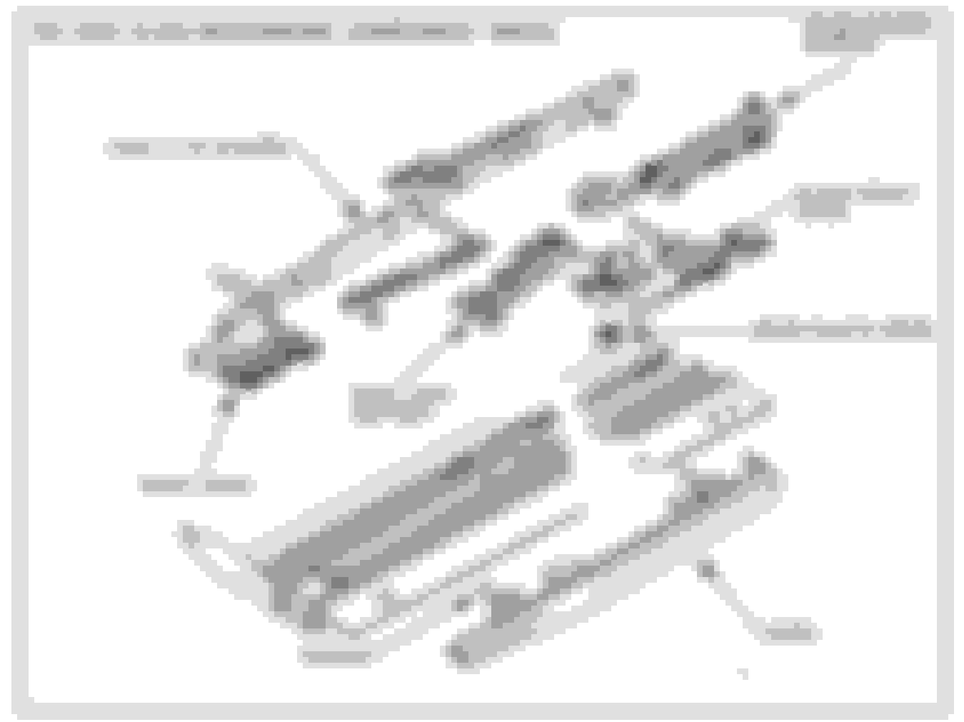
Not unexpectedly, since I have a XJ12 X300 the tilt mechanism on the sunroof has had issues. This image taken from Jaguar Tech Bulletin 13-39. On mine the Drain Channel Support broke. However I was able to find a new part from one of the Jaguar parts stores, I think SNG Barrett but not sure (it's been about a year or so). The difficulty was getting to the part, and in the course of that the shop doing the work broke the bell crank arm attached to the Main Lever Assy. This is a problem as the assembly is NLA. We found a donor car for a replacement then broke the other side (it was bent and not happy about being straightened). Pot metal and quite brittle. I took the opportunity to take all of these parts out, clean them, measure them and model them in SolidWorks. I modeled the Drain Channel Support, Slider Driven Lever, Front Lever and Main Lever Cam Slot (I think this last part is actually a metal part with a plastic overmold) as well as the bell crank. . I then did a test print in ABS to validate the models. That is as far as I took it for the plastic parts as I had everything I needed. The broken bell crank was another matter. But is solvable.
It is not intended to be removed from the assembly and is retained by the swaged end of the pivot shaft. I ground the end off the shaft with a Dremel tool, squared it up at an appropriate length, then drilled and tapped a hole (perhaps 2mm) in the end and replaced the retaining swage with a washer retained by the screw, with a thread lock compound. I found a contract 3D printer that can print in stainless steel to recreate the arm (my printer does only ABS). It wasn't terribly expensive, I recall $130 or so each, so I replaced both sides as a precaution. I needed to do some minor post print machining: reaming the bore and trimming the pins. It worked perfectly, and much stronger than the original. Problem solved. I can share the model modified for printing in stainless if anyone wants (needs?) to undertake the work.
A comment on the Solid Works models: I'd be glad to share them, however using them "as is" is perhaps not advisable. I created the models exactly as the injection molded part to serve as a starting point if I need to recreate the parts in the future. Injection molding design has a different set of engineering constraints as 3D printing. For instance injection molding geometries are created with openings for slides in the tool and to achieve a consistent crossection to avoid "wells" in the surface. 3D printing does not have these constraints, but with ABS in a Fused Deposition machine care must be taken to align the "grain" of the material with the required strength and flexure of the part. The short of it is that the 3D printed plastic parts can be made much stronger than the injection molded parts, but probably will not be as strong if create exactly as the injection molded parts. More engineering is required, and I don't have the time to do it right now. Sorry.
...I took out my headliner and just got it re- done in tweed...
I would LOVE to see a photo of that. Do you know whether there is a layer of foam or something between the cloth and the shell/board whatever the molded piece is called?
I would LOVE to see a photo of that. Do you know whether there is a layer of foam or something between the cloth and the shell/board whatever the molded piece is called?
Yeah there sure was, like Parker 2 mentioned. there is an 8th inch foam layer that is jus garbage. The tweed, was thick enough that you mount it very nicely without having to worry about bleeding of the adhesive. Don't have it in yet. just running my sunroof thorough the paces at the moment. I'll toss up a couple pics when its all done.
Last edited by Genetic_Billionaire; 07-08-2020 at 10:45 PM.
Reason: syntax errot on quote
 05-03-2020, 02:06 PM


 in terms of the modeling, it was more of an is it possible, seeing as both my 96 and my 97 XJ's need em. And I head grumbling locally about access to repair parts, as I took out my headliner and just got it re- done in tweed. Fellow at the apholstry shop said they get them in now and again with folks fooking for bits.