When you click on links to various merchants on this site and make a purchase, this can result in this site earning a commission. Affiliate programs and affiliations include, but are not limited to, the eBay Partner Network.
I've just finished fabricating my turbo manifold (thanks @XJRengineer for the manifold drawings) and now I'm interfacing AEM's piggyback ECU to the jag's ECU in order to clamp sensor signals, control timing and alter fueling strategies under boost. I've built a custom 1ft harness extension after sourcing male and female (red and black) ECU plugs and have interfaced the AEM piggyback controller's harness to the harness extension. Everything works great except when I try and intercept the crank's VR signal and supply the Jag ECU with the AEM's modified crank signal; I am able to alter timing but it will not rev above 2500 rpm. When I just "tap" the VR crank signal wire rather than "intercepting" it the car runs fine albeit with no ability to control timing. On a dual trace oscilloscope I've observed the VR signal to vary in amplitude and frequency with rpm; the piggy back ECU looks to be a 9V square wave and only varies in frequency, not amplitude. Both the input VR and piggyback's output timing signals are clean, both vary at the same frequency and appear to be locked together at the zero crossing point. The data log indicates the fuel injectors (controlled by the piggyback ECU) are cutting out, indicating a 99% duty cycle, perhaps the VR signal from the Jag to high for the piggyback controller and the piggyback controller sending a "fuel cut" signal to the injectors?
I have a working XJR ECU and rebuilt XJR injectors available but wanted to be able to data log and program fueling and ignition tables using the AEM software...
Does anyone know if the Jag ECU will only look at a VR signal or should the piggyback's 9V square wave varying at the same frequency as the VR signal work to trigger the ECU?
I am afraid I am not technically inclined to understand the modifications you have done to the engine, but I would be very interested to know how you succeeded in making an extension to the ECU. I have a few incidents of ECU being compromised by water entering the cabin or moisture finding ways to corrode the ECU connectors, and hence I have always wanted to protect the ECU from future water leak so an extension cord would help relocate the ECU from its present position under the driver's foot well.
Does anyone know if the Jag ECU will only look at a VR signal or should the piggyback's 9V square wave varying at the same frequency as the VR signal work to trigger the ECU?
Hi Bob,
What an exciting project! I am no expert in the issues you're grappling with, but a couple of thoughts come to mind.
1. As far as I know, the ECM only counts impulses or peaks in the crank sensor (CKPS) waveform and not amplitude, but I do not know if the ECM can properly interpret a square wave rather than a sinusoidal wave.
2. The stock CKPS reads TDC of both cylinders 1 and 6, so the camshaft position sensor (CMP) signal is critical for the ECM to establish initial ignition timing. Otherwise the ECM has to default to the CKPS signal which requires trial and error to establish cylinder 1 compression TDC, which can lead to long extended cranking times. Are you using the stock CMP signal or does the AEM ECU provide its own?
3. The fuel injectors in normally-aspirated X300 cars have a fuel flow rate of 220 cc/min, but those for the supercharged X306 cars can flow 380 cc/min, so part of your issue may just be fuel starvation.
If you don't have the EMS manuals, here's a link to one and I am attaching another:
I'm am trying to intercept the crank signal to modify the timing; I can see the phase shift between input and output signals when I manipulate (retard only) the timing signal. I am also intercepting the fuel injector signals and can modify the fuel injector pulses back to the ECU in either direction. Per the AEM FIC manual I've tapped into the cam position sensor signal wire and can see it's input signal on the AEM software interface. I'm still running the 19lb injectors while normally aspirated but plan on running the XJR's 36lb injectors with a 255 lph Walbro fuel pump once the turbo is installed. Again, with the crank signal just tapped (letting it pass to the ECU) I can rev to red line while in park and the injector duty cycle indicates just 22%. When I intercept the crank signal and send the 9V square wave from AEM to ECU it will only rev to 2500 rpm, pops and stumbles, interestingly the data logs indicate the injector duty cycles rapidly climbing to 99% just before it starts to miss and stumble. The injector duty cycles based on engine load so maybe the AEM FIC believes 2500 rpm the maximum load and performs a "fuel cut"- not sure.
The harness extension was fairly easy to make; I crimped and inserted pins for the female plugs; trimmed to length, soldered and heat shrunk 12 inch wires to the pins that would normally solder to the ECU's circuit board. I put different colored heat shrink on every 4th pin (something that divides in 36) so I could easily count and identify the wires pin number.
Thanks for response, The harness extension was fairly easy to make; I crimped and inserted pins for the female plugs; trimmed to length, soldered and heat shrunk 12 inch wires to the pins that would normally solder to the ECU's circuit board. I put different colored heat shrink on every 4th pin (something that divides in 36) so I could easily count and identify the wires pin number.Bob
Thank you. Do you have a picture showing the extension cord? I might try fabricating one.
Here's a pic... Ignore the wire labels. I had high quality wire left over from a custom motorcycle harness and decided to use it to construct the extension. I did actually use lacquer thinner to try and remove the printing but the ink did not come off easily. The extension allows me to not have to modify my car's harness by wiring my piggyback controller to it.
Did Andy XJR Engineer suggest a one-piece flange? The original is 2 pieces as you will know, and that will get fairly hot being turbocharged - will the alloy head and steel flange expand at different rates and stress themselves out? Or re you going to cut it in half, once fully fabricated?
I hadn't considered separating the two halves but maybe I should. Even though I was very careful to bolt the manifold to the spare head, skipping around while welding it and then letting it completely cool before removing it, the flange still warped a bit. I still want to go over my stainless steel MIG welds (I only had 035 wire available the day I decided to weld it) with my TIG welder to knock the bead down a bit and add a classic lapped pattern. After I've finished completely welding the flange inside and out I can straighten it. Hopefully by welding the interconnected tubing from manifold flange to the turbo flange (like braces) the manifold flange will remain flat. Fingers crossed....
Do you recall where you sourced the connectors and what model #s they were?
As mentioned above, a lot of us are interested in possibly relocating the ECU to keep water from leaking down the harness into the ECU in its current orientation, which is unfortunately not uncommon.
So it might be helpful to build some extension cables.
With my small collection of exhaust manifolds that I have going, I have imagined a turbo on my supercharged engine with a clutch to disconnect the supercharger at a predetermined speed. Have you thought about running the standard ECM with the standard injectors and a piggy back ECM to operate a second set of smaller injectors to come on with the boost?
Larry- I considered everything. Including a secondary set of injectors fired by a piggyback or standalone ECU. Most piggyback and stand alone ECU's have a built in MAP sensor and the fuel table can be tied to it or the car's MAF or TPS outputs at any RPM. My piggyback controller also has two Aux inputs and outputs. I can monitor voltages and other signals and load conditions to output a voltage and trigger another system.
@XJRengineer suggested I buy a supercharged ECU for my turbo project just in case I could not get my piggyback ECU working the way I want it to and I did. Just after the ECU arrived from eBay I plugged it into my car's harness with the piggyback controller still integrated. With the new XJR ECU installed the car cranked but would not fire... After a couple panic stricken moments of cranking I remembered I still had 19lb injectors not 36lb injectors. I opened the laptop and increased the injector duty cycle by 50% and the car fired right up; a tiny tweak of the MAF signal and the STFTs close to 0% Obviously, I would have to swap in the larger injectors after the turbo install and lower the injector duty cycle back, closer to 0 (no trim either way) It's also important to have an AFR gauge when tuning; I welded a bung and installed an AFR sensor just after the two header pipes merge into a single pipe prior to splitting again for the resonators. Honestly, I'm not sure how successful I will be turbo charging my jag but I'm learning a lot along the way. I bought this car new in 1996 and the jag still considered the "family car", the car my wife and I jump in to go anywhere anytime; what ever mods I make I want it to be just as dependable.
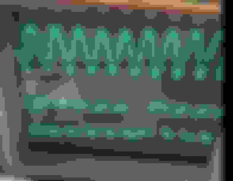
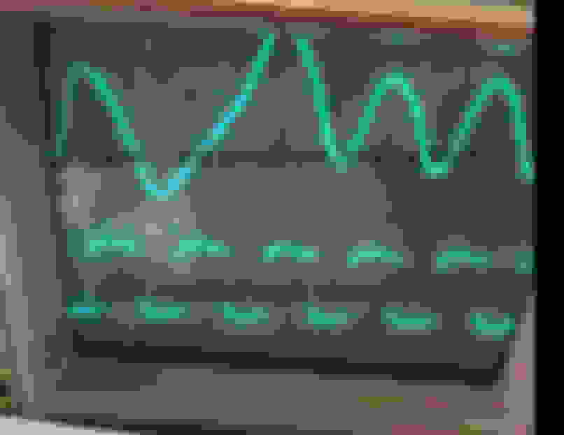
Calling on all crank trigger experts. See the images below of the factory crank signal and the modified crank signal being sent to the jag's ecu. The jag will not rev past 2500 rpm after inputting the modified crank trigger from the piggyback controller. Do you think it has to be a sine wave, not a square wave to determine the zero crossing point? Is the zero crossing point determined on the signal ramp or on signal peak? The piggyback controller manufacturer tells me the input and output signals should be identical, just slightly out of phase depending on how much timing you are trying to pull out. I know I'm old but do not believe the two signals below are identical.
Again, I'm no expert, but are either of those screen shots at or above 2,500 rpm? I'm wondering if the ECM may not be able to resolve the AEM waveform above 2,500 rpm due to its shape, given the flat peaks or plateaus.
I assume the AEM does not offer a sinusoidal waveform option? It might be worth asking AEM about this. The chip that creates the squarewave may have the capability to make it a sinewave instead with a software switch.
The screen shots are just short of 2500 rpm when the car begins to misfire. Prior to the misfire there is no change in the waveform; I just think the Jag ecu doesn't like the piggyback's modified crank signal. I still may just wind up using a supercharged ECU for the turbo install but like a snapping turtle; I just can't let go... This weekend I intend to build an RC filter that hopefully will turn a square wave into a sine wave. If the passive circuit does not modify or cause some phasing issue it will be interesting to see how the Jag ECU reacts. Still waiting on AEM to respond to the same photos sent to tech support. If I can't pull timing out using the AEM's crank trigger output, maybe I'll just tap the Jag's crank signal output for RPM reading and modify the knock sensor inputs (by sending a modified signal under certain conditions) and have the ECU pull timing based on the modified knock sensor input.
Loaner XJR6 ECM.Vehicle runs OK after programing. Long term zero always goes to 77 plus. Suspect chips are retagged X300 N/A chips. After you get done with your deal,, Would you teach me to rewrite chips for my vehicle?
Larry thanks for the offer but I already have a spare SC ECU and a spare NA ECU. When I said I modified my fuel tables I was referring to programming the fuel tables on my piggyback ECU. As far as I know @XJRengineer a former Jaguar engineer; is the one on this forum who can program the Jaguar ECUs.
I didn't think the LTFTs could read higher than +-25, yours are reading 77? Not 7.7? What are your STFT's reading?

 04-07-2019, 12:16 PM