When you click on links to various merchants on this site and make a purchase, this can result in this site earning a commission. Affiliate programs and affiliations include, but are not limited to, the eBay Partner Network.
You are probably aware that there is a Jaguar procedure for propshaft alignment. There are two different versions I have seen but I found both difficult to understand and I have not seen any posts from anyone that has actually done the job.
You may know from my previous posts that I completely rebuilt my car. I have had some driveline vibration at speed since so I decided to try the process and take a few picturess. As my car is SORN�d for winter at present (for non UK members that means officially off the road) I can�t test to see if the fix has helped until April.
Hopefully the procedure below which is a slight variation on the Jag method will help explain the process in a straight forward way.
Method
The propshaft is in two halves and is supported in the middle by the Centre Bearing. The basic objective in aligning the propshaft is to align the centre line of both halves.
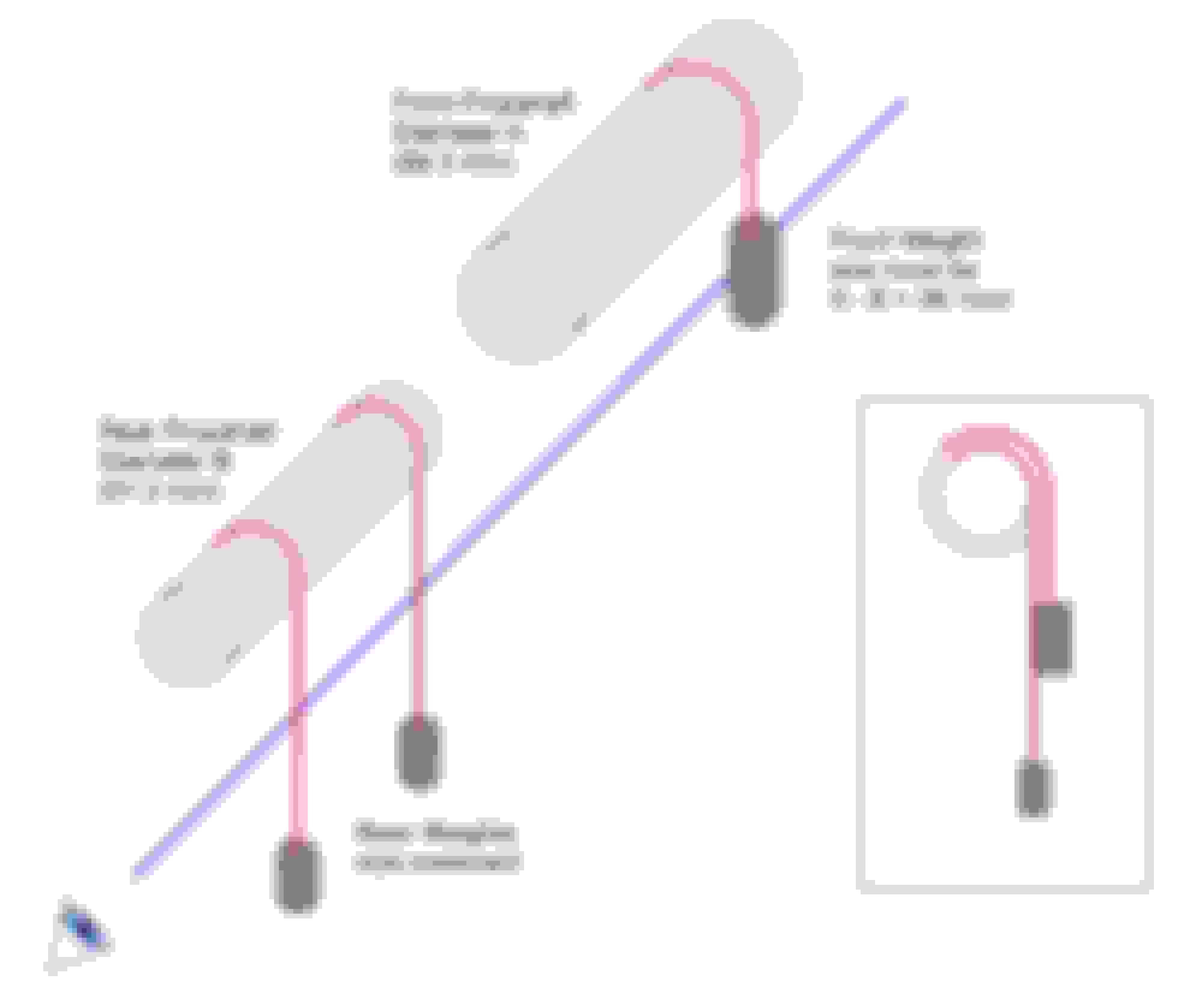
If the front and rear propshafts were the same diameter, it would simply be a case of hanging a weighted string off 3 points along the shafts and then lining them up.
As the the two halves have different diameters that adds a little bit of complication. It just means that we need to compensate for the difference in diameter in our reference points. You will see in the Factory Manual process that mention is made of a plumb weight of 38.1mm diameter.
38.1mm is the difference between the diameter of the front and back shafts. So we use that diameter weight to give a reference point which should align with the strings hanging from the smaller diameter rear shaft.
The picture below should help understanding this.
Here are some pictures of the actual use.
1. Strings and weights in place. Place two weighted strings around the top of the REAR propshaft � as close as possible to the centre bearing and the Jurid coupling. Make sure that the strings hang freely and are not touching any brackets or parts of the exhaust, and that they are not resting on any welds or balance weights on the propshaft.
The third string should be placed in the same way on the FRONT propshaft. The diameter of this weight is the important one. 38.1mm.
2. Check the alignment by looking down the three strings from the rear. Lining up the two strings on the REAR shaft, if correctly aligned, that should line up with the inner edge of the front weight (assuming it is 38.1mm as per spec). In my case it doesn�t so adjustment is required.
3. Adjust the centre bearing (and bracket if necessary) to align. By checking from the rearmost string to the edge of the front weight it is easy to work out which way the centre bearing needs to move. The picture below shows the realigned set-up.
Notes
In this method, the diameter of the weights other than the front one is unimportant.
I used large � drive impact sockets for the weights. The 27mm deep socket just so happened had a diameter of 38.1mm (as close as I could measure). I had some large wall plugs that were perfect for inserting in the sockets to get the centre point for the string.
Given that the factory process depends on lining up pieces of string by eye (which are impossible to make completely still) I think variations of 0.1mm or so here or there are not going to make a great deal of difference.
If anyone can see a problem with the approach I used then please let me know.
That is a fascinating procedure and I commend you for your ingenuity in figuring it out!
I am especially intrigued because the X300 setup is identical to the late XJ40 setup (most of the part numbers are the same for both models), yet all the XJ40 manual has to say about aligning the propeller shaft is this:
"Slacken the bolts securing the centre bearing to the mounting plate. Standing at the rear of the vehicle, 'eye' the propeller shaft centre bearing and position the mounting plate just to the left of centre. Torque tighten the centre bearing-to-mounting plate bolts."
That's the method I've used successfully, though I once had to move the centre bearing a little more leftward to eliminate a driveline vibration. Below are photos of the centre bearing replacement on our '93: An Image from the Jag-lovers Photo Album
Somewhere I read a complete contradiction to the idea of aligning the two halves of the prop shaft, stating that unless the centre bearing was positioned a little off-centre, the prop shaft would vibrate noticeably. I will be very curious to learn how yours performs after being aligned per the method in your manual.
BTW, I wasn't familiar with the term SORN, so I looked it up and added it to my list of Acronyms, Abbreviations and Terms (see link in my signature) and I credited you for the addition.
How would you deal with the obstructions of the exhaust and center bearing assembly?
Don
Haven't seen it, so don't know
But a laser shoots a straight line. You just have to decide what to shoot.
If one were to hang weighted loops from each point of interest, the center of
the gap is the center line. Once the laser is adjusted to shoot through the
center points of the two ends, any intervening loop can be centered
along that line. I often use white rulers or file card stock as laser targets.
If you use a magnetic laser level, you could attach at one end of the driveshaft
and shoot to the other end. I don't know if it hangs down far enough. Mine
has a 2" offset from the base.
The point made by Don B is correct, in that the shafts are not intended to be absolutely straight. The procedure set out in JTIS is very very similar to that described by b1mcp, with one important difference; the diameter of the weights on the plumb lines is critical, as the rear plumb lines need to be aligned with "the outside diameter" of the front weight. The front weight being the wider diameter, this would result I guess in the required degree of offset. Lining the plumb lines up with one another as suggested by bimcp would produce a completely straight driveline, and while that is what we would all be inclined to think is the ideal, it is seemingly not what Jaguar had in mind.
Lining the plumb lines up with one another as suggested by bimcp would produce a completely straight driveline, and while that is what we would all be inclined to think is the ideal, it is seemingly not what Jaguar had in mind.
U-joints *require* a small amount of angle to work properly....usually something like .5� to 3.5�.
Something about cancelling out non-uniform velocities. Or the co-efficient of linear expansion. Or something like that!
I don't understand the science of it but there's plenty of info out there.
I'm happy to believe that there should be some misalignment based on your collective feedback.
My process was based primarily on the Jaguar procedure described in the TSB 09-01. I've attached for information.
Unless I'm misunderstanding that document it would appear to suggest a straight line alignment of the front and rear shafts. Where that document describes measuring the difference between front and rear shaft diameters and adjusting to get the "offset" to match that, I have just used a fixed size weight to provide the same reference/adjustment measurement point.
Perhaps we should just stick with Don's suggested line it up by eye, a bit to the left.
- there is one obscure version of the Jaguar procedure which actually states
that "the goal is to align the two drive shaft segments in a straight line.
I have four different pdf's open and can't find it, but did read it within the last week
- the above statement agrees with the alignment procedure as laid out by b1mcp
- the tsb is very similar to the version in the manual, the difference being that the
reader is asked to calculate the offset rather than being given the offset
Given the above, it is possible to avoid the offset calculation or considerations.
If three loops of string are hung at the same three places as before, and three
loops of weighted string are then hung from those loops, gravity will force the
three weighted loops to hang from the apexes of three inverted isoceles triangles.
Being the apex of an isoceles triangle, the apex will by definition be on the center
line of driveshaft since the driveshaft forms the base of the triangle.
The weighted loops will be a straight line due to the force of gravity, and the
lines will extend from the center of the driveshaft.
however
and this may be quite controversial ...
When I first read the alignment procedure, I thought that the differences in
size of the weights was due to a need to dogleg the driveshaft given the
offset of the pinion flange on the 15HU differential. The offset is 1.25 inches.
Whether the ends of a ujointed shaft are offset vertically or horizontally,
the ends must have the same angle at both ujoints to operate smoothly.
This is angular velocity cancellation, fwiw.
This is well known in the engine swap and 4x4 lift communities
So, it is perfectly permissible to operate with an offset, and one would
want the driveshaft to be a perfectly straight line between those ujoints.
Now I am thinking that the procedure was carried over from the Series,
XJ40 and XJS legacy where there were ujoints at the pinion flange.
The fly in the ointment is that starting with the X300, there is a jurid
coupling at the pinion flange instead of a ujoint.
The rearward ujoint is now at the rear of the front half of the driveshaft.
As such, it is the joint that has to be aligned at the same angle as
the front joint given that there is no further rearward ujoint.
The rear part of the driveshaft is more like a jack shaft extending
the pinion flange to the center bearing where it meets the front
shaft.
The jurid coupling does not operate like a ujoint. It has elasticity
and will want to whip. And of course, flexing rubber eventually
cracks the rubber.
Therefore, I suggest that the optimal setup on a X300, or modified X308
with the offset pinion 15HU differential is to align the rear shaft
parallel to the vehicle centerline, and let the front shaft complete
the angle compensation. In effect, the pinion flange is extended
to the center bearing.
Some of you know that I have been playing with transplanting a
15HU to a X308. The X308 uses the 14HU which has a centered
pinion flange and thus this is not a consideration. However, I
first heard of this dogleg requirement in reading information about
the transplant.
The Series XJ Saloons have both vertical and horizontal alignment
procedures. The short version is that the horizontal alignment
procedure is to offset the driveshaft 1/8 inch at the center bearing
to the left. Thus, it is doglegged.
Now I am thinking that the procedure was carried over from the Series, XJ40 and XJS legacy where there were ujoints at the pinion flange.
The fly in the ointment is that starting with the X300, there is a jurid
coupling at the pinion flange instead of a ujoint.
plums,
I may have to go back to college before I have a chance of comprehending your essay, but for the record, except for the very early cars, XJ40s were equipped with Jurid flexible couplings at the pinion. Our '88 had a Jurid, as does our '93.
A new design drive shaft, constructed of thin wall tubing, reduces total weight and improves
drive shaft balance. The on-center pinion design of the 14 HU final drive unit and the reloca-
tion of the drive shaft center bearing allows in-line shaft installation, which reduces the univer-
sal joint operating angles and resulting vibrations.
plums,
If I read the above correctly, the X308 with the 14U diff should have both sections of the driveshaft aligned in a straight line, but the very clear implication is that X300s and XJ40s with their offset diffs should not have their driveshafts aligned with both sections in-line?
First let me correct the attribution of a statement that went missing
because of an error.
It was Jaguar themselves who said:
A new design drive shaft, constructed of thin wall tubing, reduces total weight and improves
drive shaft balance. The on-center pinion design of the 14 HU final drive unit and the reloca-
tion of the drive shaft center bearing allows in-line shaft installation, which reduces the univer-
sal joint operating angles and resulting vibrations.
And the reason it got worse for X308 owners wanting to swap to a X300 15HU
is that there is only one ujoint which makes it impossible to do what is considered
necessary by ujoint and driveshaft vendors when angles are involved.
That is, the two endpoints must run at the same angle to cancel vibration.
That requires two or more ujoints depending on how many planes are
being considered. One ujoint makes this impossible.
Although, the owners of two XK's on JF have done the swap, and they
only have one ujoint as well.
If I read the above correctly, the X308 with the 14U diff should have both sections of the driveshaft aligned in a straight line, but the very clear implication is that X300s and XJ40s with their offset diffs should not have their driveshafts aligned with both sections in-line?
Is that your conclusion as well?
Cheers,
Don
There are two parts to that.
On the X308 with the factory issue 14HU, there is no choice but straight
as there are only two flexible joints. One at the front being a ujoint, and
one at the rear being a flex coupling.
The change was facilitated by a move to a center pinion diff. That's
how they got away with dropping one ujoint.
The situation is different on the X300/XJ40 in that the center lines of
the transmission and differential are offset. The transmission tail is
on the center line while the pinion nose is about 1.25 inches to the
right of center.
My suggestion is that the flex coupling would be happier running
without having to flex/wobble at an angle.
edit: see post #20 before making a final decision
This can be accomplished by having the rear part of the shaft run
straight out from the pinion flange and then doing all the angling
on the front shaft to meet the rear shaft at the center bearing.
The front and rear ujoints on the front half must run the same
angles relative to horizontal and vertical planes.
The center bearing can be adjusted vertically, although this has
fallen out of the documentation from earlier versions. The adjustment
plates still exist in the parts catalog.
Ujoint manufacturers allow designers to have up to 2 degrees differential
between the front and rear ujoints although of course zero is preferred.
Flex joints also have some small degree of freedom.
If you consider the vehicle in plan view with the hood at the top
and the trunk at the bottom, the two parts of the shaft as the
hands of a clock centered at the center bearing would resemble
11:30 o'clock with the hour hand touching the transmission and the
minute hand touching the differential.
This whole exercise of equal angles front and back also has to
be checked for the vertical plane.
This can normally be accomplished with a digital angle gauge.
One thing to remember is movement of the pinion nose on a
IRS system is much more limited as compared to a live axle.
My usual cynical comment is that while flex disks approach
3 digit costs, ujoints are much cheaper, stronger and durable.
It certainly makes swapping the 15HU into an X308 less straightforward
and more expensive if one wants that second ujoint.
Thanks for the extra explanation and sorry again for my error that caused the loss of part of your previous post.
I follow the mental imagery of your description except if the hood is on top of the diagram wouldn't the hour hand of the clock touch the transmission? Or should the hood be at the bottom and the trunk at the top?
I'm grateful for your knowledge and willingness to share it with the rest of us!
I follow the mental imagery of your description except if the hood is on top of the diagram wouldn't the hour hand of the clock touch the transmission? Or should the hood be at the bottom and the trunk at the top?
Yes. That part of the description did not get changed when the time was
changed from 5pm. Since the edit window is open, I went back and
corrected that. At least I know someone is reading
A bit more information. The allowable angular misalignment spec for the
flex disc seems to be as little as 1 degree. If the prop shaft is 60 inches,
that would be just about 1 inch.
Now, this is specific to the X300:
just saw a diagram that may explain why the alignment procedure on the
X300 is a straight line. It is only a line drawing but it seems the spigot
for the transmission mount is also offset to the right. If it is offset by the
same amount as the differential pinion, that would make a straight line
the right choice.
Someone else can confirm since there is no X300 handy here to crawl
under.
BTW, it seems that the BMW and Mercedes boards are also filled with
people who are less than impressed by URO brand flex couplings.
One famous story on the Mercedes boards is that of someone installing
a URO brand coupling that totaled the car. The coupling failed which
was enough to deploy all airbags resulting in an insurance writeoff
due to cost of replacement. Not a scratch on the car though.
 03-04-2015, 10:39 AM