What?! LED Backlights Dimming.
#1
 07-03-2010, 01:21 AM

NOTE: I'm not going to tackle the backlighting of the gauge cluster behind the steering wheel at this point in time, but when I do, I'll update this thread.
This thread was initially started because I noticed that the X300 actually uses PWM for it's dashboard backlight dimming function. This was great news, as it meant that the dimming function would work with LED backlights too. Then I went on a mission to replace the backlights in my X300... I've compressed all the useful info into this first post (hopefully making it easier to understand).
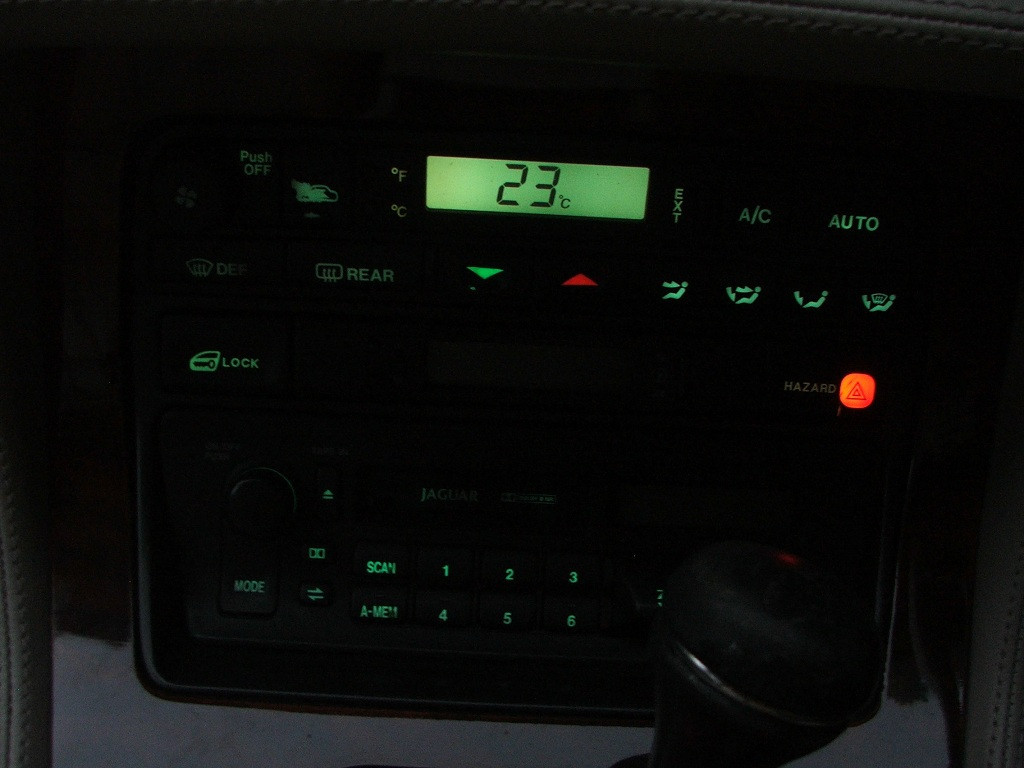
I'd just torn my X300's ski slope apart to replace the 'NOT CONT'ing stereo when I noticed that some of the backlights in my air-con module were not working. So I thought it might be smart to replace the lot with LEDs. LEDs should last longer, look better and run cooler. In fact, excessive heat from stock incandescent backlights is the root of the infamous X300 clock problem.
After some research, I discovered that Jaguar uses a fairly obscure twist lock fitting called 'neo-wedge' for these backlights. Only a few stores can supply neo-wedge LEDs, but there was still enough choice to confuse the hell out of me.
Auto Illumination
Super bright LEDs
BL LED Optronics
I ended up purchasing my neo-wedge LEDs from BL LED Optronics Australia, the main reason for this being that when I discovered them via E-Bay, they had more detailed images of the product than any of the other shops I'd looked at. I also noticed that ALL of their Neo-Wedges (even the T3s) had flat tipped lenses (resulting in a less focussed beam, thus better for backlighting), that they appeared to be standard LEDs (not the super intense SMD LEDs which would have been totally unsuitable for backlighting) and that the Neo-Wedge bases appeared to be closer to the 90� turn Jaguar bases than any of the others I'd seen. Their prices seemed very competitive, although this only aroused suspicion in me as to the quality of the items. I took a chance, and I guess only time will tell whether these LEDs are rubbish or not. (19/04/2012 Note: No LED failures thus far).
What I will say, is that BL LED Optronics were great to deal with. Fast communication and dispatch of goods. And I got exactly the colours and sizes I asked for.
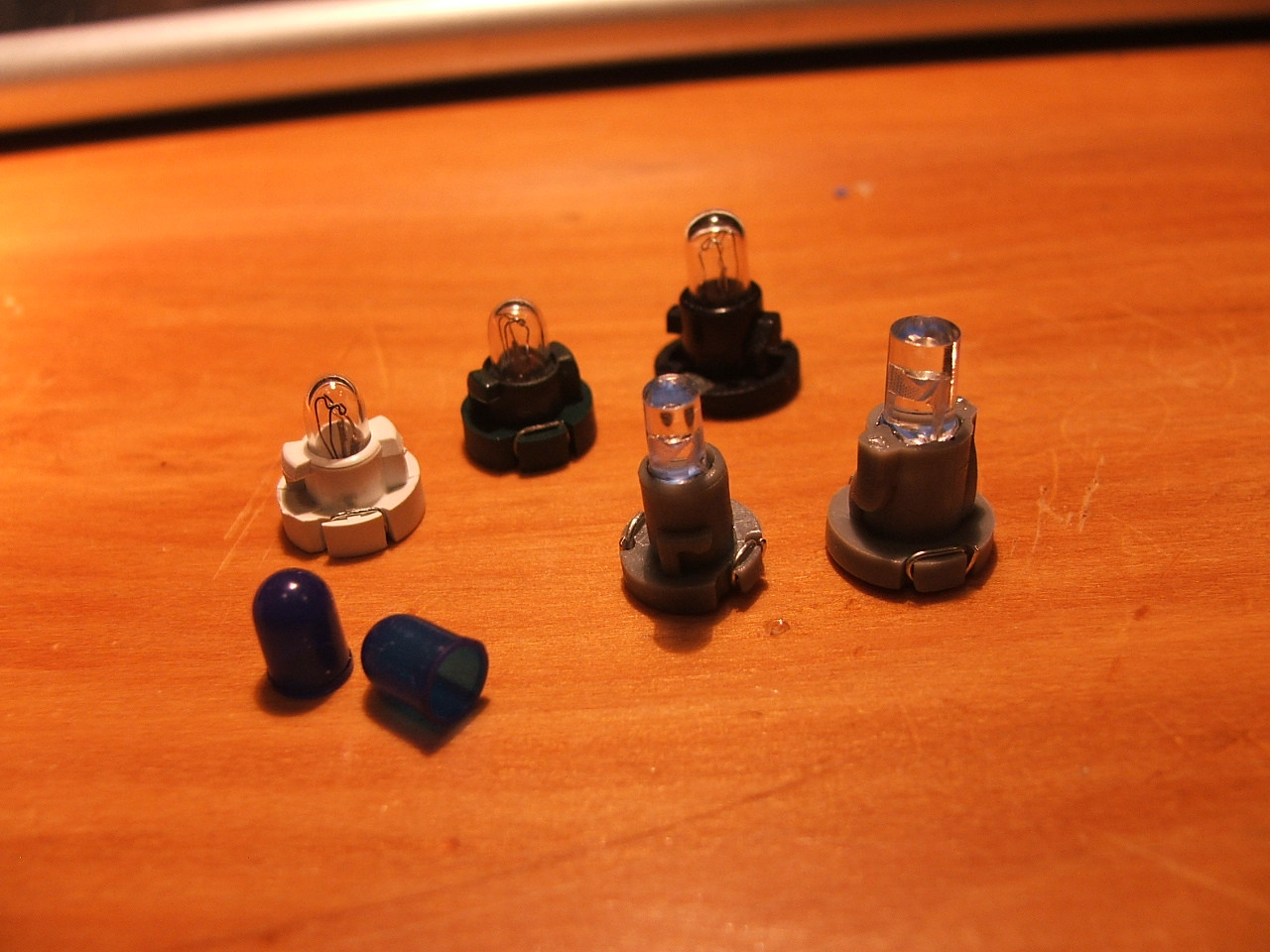
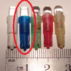
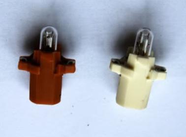
Neo-wedge: Stock incandescent backlights with T3 and T4 LEDs (note the blue silicone caps which are used on the stock lights to give them their greenish glow [blue = green? don't ask...]).
Jaguar's neo-wedge sizing:
There are two different calibres of neo-wedge used in the X300. The larger ones are T4, so the T4 LED replacements fit perfectly. However the smaller ones (abundant in the climate control module) are not T3. They're somewhere between T4 and T3, a size that doesn't seem to be used anymore. T3 units may be installed, but they felt a little loose, and I wouldn't trust them to remain in place in the long term (car vibrations etc.).
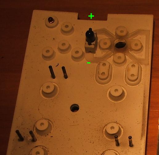
My solution to this minor problem, was simply to enlarge the smaller sockets to accommodate T4 units. This was an easy decision, as it required minimal modification and meant that all the LED bulbs would be exactly the same size throughout the centre console (easier to maintain light uniformity). The diagram below depicts a neo-wedge socket:

All you need to do is take some drill bits (start with one that is just marginally larger than the socket aperture), and working it with your fingers, gently shave off the inner layer of PCB as indicated by the red ring (2). You shouldn't need to cut into the silver contacts, but if you do, be careful that they don't start to lift and peel off the PCB. I think I only needed to use a 5/64 bit to make my T4's fit. You can also use a fine needle file for minor adjustments. One thing you should consider is where all the debris is falling. I disassembled my modules to ensure that I could remove all the dust etc.:

So far, every LED backlight I've installed has been derived from the T4 neo-wedge unit I purchased from BL LED Optronics.
BL LED Optronics stock a range of colours, including white, blue, green, red and amber. I was torn between blue and green, so I bought some of each to trial. To my eyes, the brilliant spark-blue lights were most pleasing.

Testing the LEDs with a power pack.
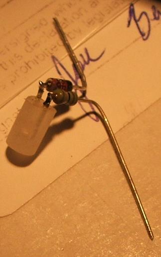
They are actually more than just an LED. Inside the plastic base you will find a resistor, and also a diode to protect the LED should you connect it the wrong way around. Thanks to this reverse polarity protection, you can simply install them one way and then turn them around if they don't work. However, for future convenience you might want to go over the Jaguar sockets with a multimeter, and mark the polarities. (Note: socket polarities are now illustrated further into this post)
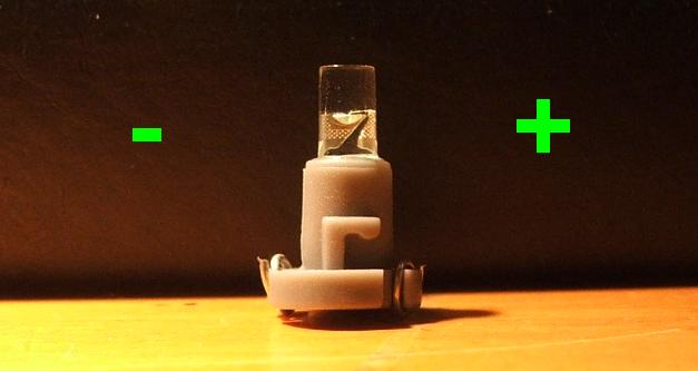
You can tell the polarity of an LED bulb by looking at it's structure inside the lens. The cathode is the larger part and is the negative side of the LED. The smaller anode is positive:

Close up neo-wedge LED.
Of course if you're frosting the lenses as I've done below, you wont be able to see this structure, so it's a good idea to mark the positive side of the base with a permanent marker or something before you make any modifications.
When I first installed the LEDs, they were ridiculously bright, but I was expecting this, having been warned by 6cylinderDOHC on the UK Jag forum. Even with the Jag's dimmer switch at minimum, they were bright enough to be highly distracting (and other shops were boasting backlights twice as bright! What's the point?). So I set about finding a good way to tame them.
My first course of action was to 'frost' the lenses in order to dim and diffuse the light (LEDs are far more directional than the stock incandescent backlights, and these ones were not doing a very good job of providing uniform backlighting of the clock/air-con LCD displays). I used sandpaper (220 grit) to rough the lenses so that they were translucent rather than transparent. It took some patience to get an even finish, and when I re-installed the LEDs to test them they were still too bright and too focused, despite a vast improvement.
My next experiment involved coating the lenses in white enamel paint. This process was extremely tedious and I was still not happy with the result (inconsistent light distribution/intensity etc.)

This is my original trial painting the LEDs:


Superior Method of Dimming Neo-Wedge LEDs - Increased Resistance and Frosting
This method produces a much more predictable result that the painting method, and should hopefully increase LED lifespan. It involves 'frosting' the bulb surface with sandpaper, and also installing new resistors. (I asked a few of the neo-wedge suppliers if they'd pre-install resistors of my choice, but none would comply.)
I used a decade box to test the backlights at various levels of resistance:

Here is a frosted LED with 10000 ohms of resistance beside one of the stock incandescents:

The camera is a bit deceptive (the LED's 'spark blue' appears to have more 'impact'), but that LED is just about spot on stock intensity. No more painting
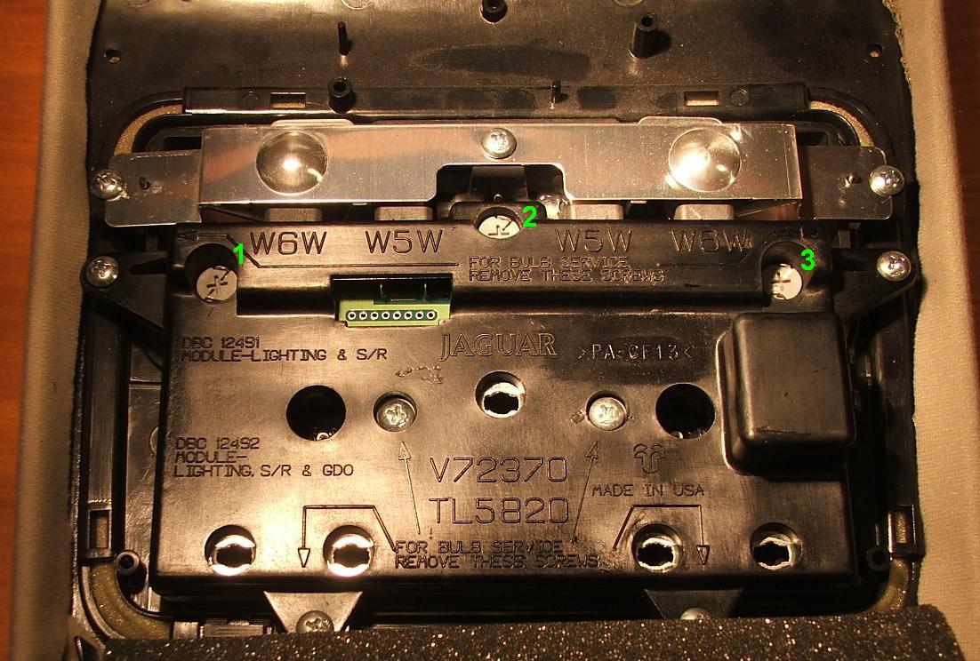
10k resistors appeared best for general use, while I used 8.2k for white LEDs and screen backlighting. Screen backlights were soldered directly to the PCB and positioned at 90� facing inwards (see below). NOTE: Using the stock resistor for the 90� screen backlights produces better uniformity and distribution for daytime use, but in my opinion was too bright for night use. With the 8.2k resistors, the screens better match the buttons at night, but appear more 'blotchy' in broad daylight.
This was my final configuration:
Clock Module:
1) T4 Neo-Wedge.........8.2k
2) T4 Neo-Wedge .........10k
3
4) 90� Soldered..............8.2k
5) 90� Soldered..............8.2k
6)
7) T4 Neo-Wedge .........10k
Air-con Module:
1) T4 Neo-Wedge .........10k
2) T4 Neo-Wedge .........10k
3) T4 Neo-Wedge .........10k
4) 90� Soldered..............8.2k
5) T4 Neo-Wedge..........8.2k
6) 90� Soldered..............8.2k
7) T4 Neo-Wedge .........10k
8) T4 Neo-Wedge .........10k
9) T4 Neo-Wedge .........10k
10) T4 Neo-Wedge ...... 10k
Ceiling Console:
1) T4 Neo-Wedge .........10k
2) T4 Neo-Wedge .........10k
3) T4 Neo-Wedge .........10k
NOTE: I didn't increase the resistances to the door backlights, as they have a hard enough time distributing enough light with the stock resistor.

Clock Module.

Air-con Module.
Ceiling Console.
Replacing Resistor - Removal and Re-Installation of LEDs in Neo-Wedge Bases:
A) Unwind the two wires and straighten them with pliers (don't bend them around too much or they will weaken and break):
B) Gently work the LED out of the plastic base. You'll probably have to rock it from side-to-side a couple of times to break the glue. The stock resistor and/or the glass-cased diode might become disconnected in the process:

NOTE: There was some overzealous glueing evident in a few of the neo-wedge LEDs I purchased, which made it impossible to extract the LED and it's components without destroying the base. For this reason, it's important to buy extras.
C) Remove any glue from the plastic base, LED or other components.
D) De-solder the stock resistor, and cut the new one to match:

I found a pair of locking surgical forceps very useful for holding this still during soldering.
NOTE: Resistors are bipolar, so it doesn't matter which end is connected to the LED.
E) Attach the new resistor, and re-attach the diode if it came off.

NOTE: The resistor needs to be on the positive side of the LED and the diode on the negative, make sure they don't get mixed up.
F) 'Frost' the entire LED by sanding it with a fine sandpaper until it becomes translucent.
G) Re-install the LED into it's Plastic base.
IMPORTANT! To prevent conflicts with buttons:
- Neo-wedge lights to be used in the ceiling console must be shortened. Just sand ~1.5mm off the end of the LEDs during the frosting process. Make sure you don't sand through to the metal parts inside the LED.

- Neo-wedge lights to be used in the clock module must have their plastic bases shortened. Slice ~2mm off the top of the base with a sharp knife before re-installing the LED.

Better LCD Backlighting - 90� Mounting
I had two X300 clocks repaired by ModuleMaster recently, and their repair includes LED backlighting for the LCD screen. Of course, I wanted to mange my own backlighting for my car, so I told them to exclude the procedure from my clock. I let them modify the other clock though, and I'm glad I did because their strategy might be the best so far! They simply mounted their LEDs at 90 degrees so they weren't pointing directly at the screen (why didn't I think of that?). The result is an incredibly even distribution of light across the screen, and I've been able to re-create this in my clock and air-con screens.
There are some downsides:
- The colour of the light is whitened because all of it is refracting through, or reflecting off the white plastic structure behind the screen.
- A 'drop in' solution is virtually impossible. You have to solder the LEDs directly to the PCB.
I think it's worth it though.
You need to solder the resistor and diode to the LED at 90 degrees, and then bend the legs so that they'll sit on the contact solder pads around the neo-wedge sockets, paying attention to polarity:
Positioning of legs for air-con screen.

Positioning of legs for clock screen.
Then solder them in place, both facing inward:

Once they are soldered in you can gently reposition them to make sure they are parallel with the screen:

Sorry about the poor focus, my camera's screen is barely larger than a square inch. As always, the lights looked much better in real life:

This is a photo of an X300 with stock backlighting installed - taken for comparison.
Ceiling Backlight Notes:
To access these, you simply remove the rachet fastener hidden behind the sunglasses compartment door. Use a coin (or whatever) to turn it 90�, and the ceiling console will loosen. Pull the unit down and towards the rear of the vehicle to remove, uncliping the wire harness.
I was also worried about these backlights, as they had no rubber cap on them (the colour filter is actually inside the buttons, and I thought that this might make the characters glow a different clour from my ski-slope lights) but luckily, the spark blue of the LEDs seemed to overpower the stock green filter without being altered at all:
X300s featuring a sunroof will have more than three neo-wedge lights to replace.

Door Backlights:
To access the backlights:
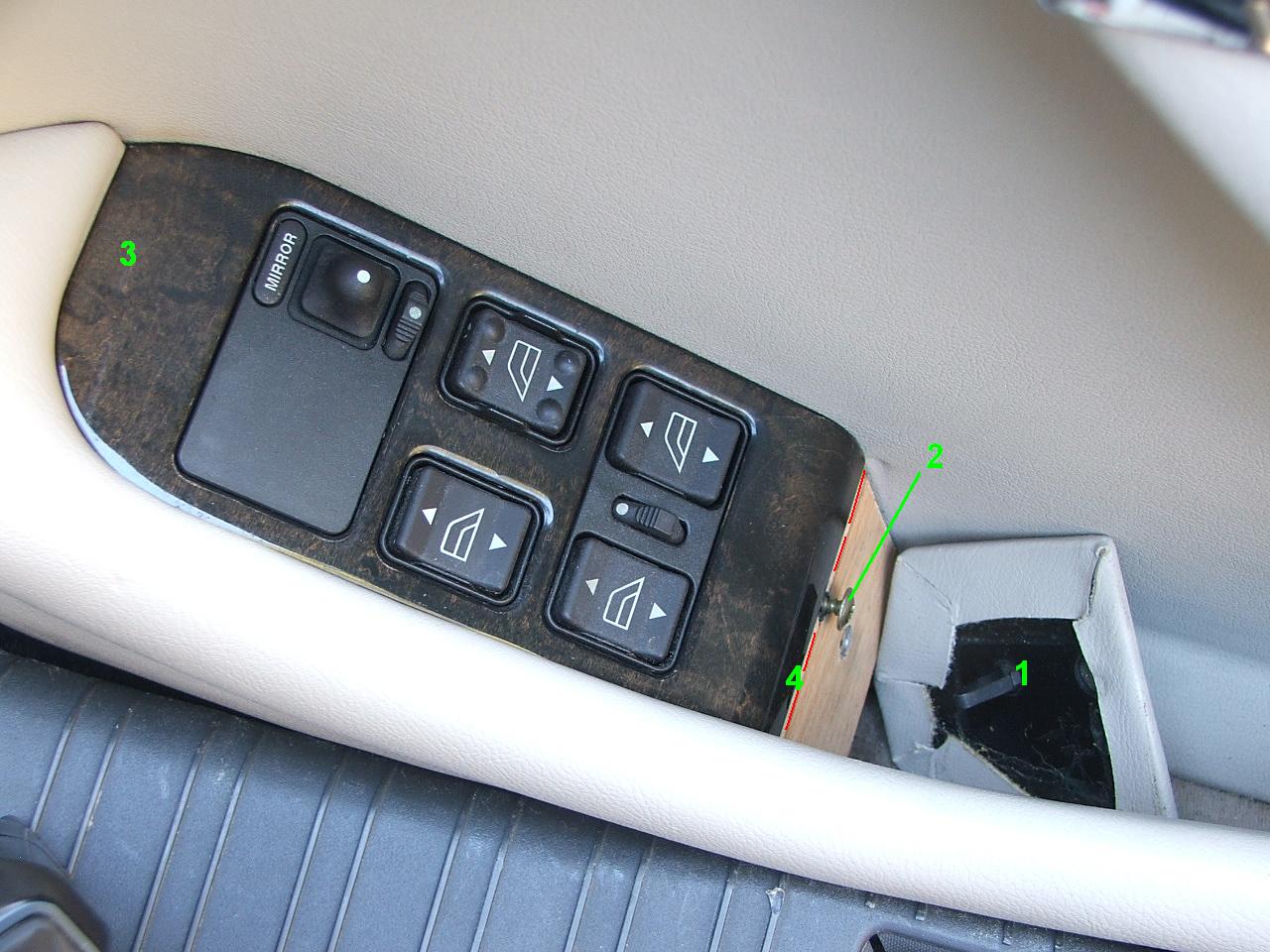
The little leather-clad plastic cover (1) just pulls away using fingernails or something blunt (so as not to damage the leather). Now remove the exposed screw (2).
On the underside of this wood trim, towards the front end, there is a metal tab (3) which hooks under part of the plastic switch box. So to remove the wood trim you need to gently lift it up (there is just enough of a lip (4) here to grasp), and slide it back. It might be jammed rather tightly between the leather on one side, and plastic on the other side, so be careful not to flex it too much and crack the veneer.
Now the top of the plastic switch box will be exposed, and next to some of the switches there will be tiny translucent blue panels. These are actually the cartriges containing the backlight bulbs. Gently work these cartriges up and out of the swich box. Depending on the car, there will be 2-3 cartriges. The drivers door is the only door with multiple backlight bulbs. The other three use just one, accessed the same way.

The cartriges consist of a blue plastic casing which clips around a white rubber brick. The bulb fits into the rubber brick, and it's wires are fed up through holes on either side. When installed, the holes press down on to metal prongs in the socket.

Stock door backlights - these ones also use coloured silicone caps.
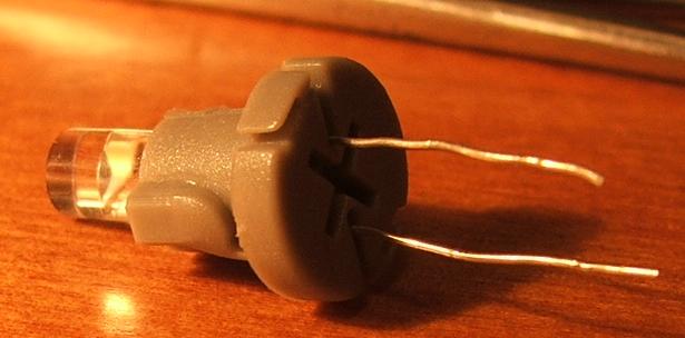
Now I wanted to find a way to use LEDs in the doors. I removed one of my T4 LED's from it's neo-wedge base:

Including the components on either leg, they're about the size of one of the stock incandescent lights, so they fit into the rubber mounts just fine.
I must confess that installing the ex-neo-wedge LEDs in these tiny cartriges is no fun at all. Firstly, the legs of the LEDs are much thicker than those of the original incandescents, so I't a nightmare feeding them up through the holes. Secondly, the solder joints where the components join the led's were always breaking, so I had to take them out, re-solder the joints, and start again. A fools errand, to be sure!

Frosted LED vs stock incandescent.

Door Backlights Continued - The Hidden Mirror Switch Backlight:
I had all the visible backlight cartriges removed, when I noticed a problem: the mirror controls in the drivers door were still backlit. Unfortunately, there is no way to access that particular bulb without dismantling the entire door (a very stupid move on Jaguar's part). If you're keen to waste a lot of time and effort for one miserable backlight, here are some guidelines:
You'll need to remove the interior trim panel from the door (a drama in itself), then disassemble the trim panel to acces the switch box.
1) Once you have removed the black switch box from the door, turn it over and there should be a single screw right in the centre (it might be concealed by a sticker). Remove the screw.
2) The casing will still be held together by a plastic clip at either end, so gently lift them to open it.
3) Unclip the two ribbon cables by lifting the socket clamp out and up.
4) The PCB that the ribbon cables were connected to is held down by two screws at one end. Remove them.
5) Now you should be able to lift out the PCB with it's rubber cladding. Do this carefully as there are lots of tiny plastic parts beneith.
The mirror backlight will now be accessible.
If you're installing an LED, remember it can only work one way around. Polarity is as pictured below, although It would be wise to connect the switchbox to the car and double check prior to reassembling the door:

More photos of the switch box internals:
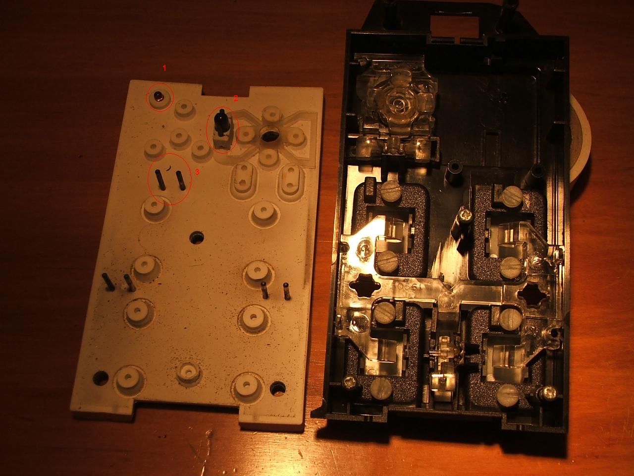
2 = The mystery mirror control backlight (why didn't they make it accessable like the other two/three)
3 = Contacts for backlighting whatever extra controls are included in high spec cars. This has an access hole included in such cars (mine just has the depression where the hole would be)
1 = I wonder what this thing is??? it certainly isn't an active backlight...
reverse:
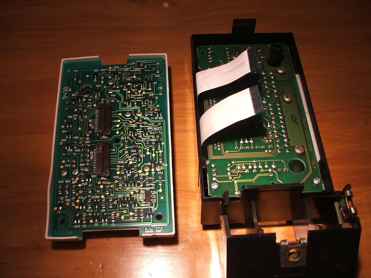
What a lot of circuitry!
'J-Gate' Lighting:
I opened everything up expecting to find separate incandescents for each stick position. But Jaguar have actually usedtiny little LEDs as shown here:

So the only light to replace is the incandescent that lights up the whole thing, and this can be accessed by simply removing the three trim rings the go around the J-Gate. The stock light is a T5 mini-wedge incandescent with a 5mm base. There are plenty of LED replacement options available. I used this: http://www.ledbulbs.co.nz/automotive-leds/dash-board-leds/t5-74-led-bulb
I also tried the SMD LED type, but it was far too bright.
[Note on removing and installing J-Gate bulbs: It's really easy to drop the damn things, so make sure you grip them firmly with something. I dropped a little glass bulb down into the shifter mechanism, never to be seen again. I hope it doesn't smash down there and jam anything!]
You will notice that the upper part of the J-Gate is not very well illuminated (between P and R). Well that seems pretty much impossible to light uniformly, even with the stock solution.

The End (Until I add the gauge cluster)
This thread was initially started because I noticed that the X300 actually uses PWM for it's dashboard backlight dimming function. This was great news, as it meant that the dimming function would work with LED backlights too. Then I went on a mission to replace the backlights in my X300... I've compressed all the useful info into this first post (hopefully making it easier to understand).
I'd just torn my X300's ski slope apart to replace the 'NOT CONT'ing stereo when I noticed that some of the backlights in my air-con module were not working. So I thought it might be smart to replace the lot with LEDs. LEDs should last longer, look better and run cooler. In fact, excessive heat from stock incandescent backlights is the root of the infamous X300 clock problem.
After some research, I discovered that Jaguar uses a fairly obscure twist lock fitting called 'neo-wedge' for these backlights. Only a few stores can supply neo-wedge LEDs, but there was still enough choice to confuse the hell out of me.
Auto Illumination
Super bright LEDs
BL LED Optronics
I ended up purchasing my neo-wedge LEDs from BL LED Optronics Australia, the main reason for this being that when I discovered them via E-Bay, they had more detailed images of the product than any of the other shops I'd looked at. I also noticed that ALL of their Neo-Wedges (even the T3s) had flat tipped lenses (resulting in a less focussed beam, thus better for backlighting), that they appeared to be standard LEDs (not the super intense SMD LEDs which would have been totally unsuitable for backlighting) and that the Neo-Wedge bases appeared to be closer to the 90� turn Jaguar bases than any of the others I'd seen. Their prices seemed very competitive, although this only aroused suspicion in me as to the quality of the items. I took a chance, and I guess only time will tell whether these LEDs are rubbish or not. (19/04/2012 Note: No LED failures thus far).
What I will say, is that BL LED Optronics were great to deal with. Fast communication and dispatch of goods. And I got exactly the colours and sizes I asked for.
Neo-wedge: Stock incandescent backlights with T3 and T4 LEDs (note the blue silicone caps which are used on the stock lights to give them their greenish glow [blue = green? don't ask...]).
Jaguar's neo-wedge sizing:
There are two different calibres of neo-wedge used in the X300. The larger ones are T4, so the T4 LED replacements fit perfectly. However the smaller ones (abundant in the climate control module) are not T3. They're somewhere between T4 and T3, a size that doesn't seem to be used anymore. T3 units may be installed, but they felt a little loose, and I wouldn't trust them to remain in place in the long term (car vibrations etc.).
My solution to this minor problem, was simply to enlarge the smaller sockets to accommodate T4 units. This was an easy decision, as it required minimal modification and meant that all the LED bulbs would be exactly the same size throughout the centre console (easier to maintain light uniformity). The diagram below depicts a neo-wedge socket:
All you need to do is take some drill bits (start with one that is just marginally larger than the socket aperture), and working it with your fingers, gently shave off the inner layer of PCB as indicated by the red ring (2). You shouldn't need to cut into the silver contacts, but if you do, be careful that they don't start to lift and peel off the PCB. I think I only needed to use a 5/64 bit to make my T4's fit. You can also use a fine needle file for minor adjustments. One thing you should consider is where all the debris is falling. I disassembled my modules to ensure that I could remove all the dust etc.:
So far, every LED backlight I've installed has been derived from the T4 neo-wedge unit I purchased from BL LED Optronics.
BL LED Optronics stock a range of colours, including white, blue, green, red and amber. I was torn between blue and green, so I bought some of each to trial. To my eyes, the brilliant spark-blue lights were most pleasing.
Testing the LEDs with a power pack.
They are actually more than just an LED. Inside the plastic base you will find a resistor, and also a diode to protect the LED should you connect it the wrong way around. Thanks to this reverse polarity protection, you can simply install them one way and then turn them around if they don't work. However, for future convenience you might want to go over the Jaguar sockets with a multimeter, and mark the polarities. (Note: socket polarities are now illustrated further into this post)
You can tell the polarity of an LED bulb by looking at it's structure inside the lens. The cathode is the larger part and is the negative side of the LED. The smaller anode is positive:
Close up neo-wedge LED.
Of course if you're frosting the lenses as I've done below, you wont be able to see this structure, so it's a good idea to mark the positive side of the base with a permanent marker or something before you make any modifications.
When I first installed the LEDs, they were ridiculously bright, but I was expecting this, having been warned by 6cylinderDOHC on the UK Jag forum. Even with the Jag's dimmer switch at minimum, they were bright enough to be highly distracting (and other shops were boasting backlights twice as bright! What's the point?). So I set about finding a good way to tame them.
My first course of action was to 'frost' the lenses in order to dim and diffuse the light (LEDs are far more directional than the stock incandescent backlights, and these ones were not doing a very good job of providing uniform backlighting of the clock/air-con LCD displays). I used sandpaper (220 grit) to rough the lenses so that they were translucent rather than transparent. It took some patience to get an even finish, and when I re-installed the LEDs to test them they were still too bright and too focused, despite a vast improvement.
My next experiment involved coating the lenses in white enamel paint. This process was extremely tedious and I was still not happy with the result (inconsistent light distribution/intensity etc.)
This is my original trial painting the LEDs:
Superior Method of Dimming Neo-Wedge LEDs - Increased Resistance and Frosting
This method produces a much more predictable result that the painting method, and should hopefully increase LED lifespan. It involves 'frosting' the bulb surface with sandpaper, and also installing new resistors. (I asked a few of the neo-wedge suppliers if they'd pre-install resistors of my choice, but none would comply.)
I used a decade box to test the backlights at various levels of resistance:
Here is a frosted LED with 10000 ohms of resistance beside one of the stock incandescents:
The camera is a bit deceptive (the LED's 'spark blue' appears to have more 'impact'), but that LED is just about spot on stock intensity. No more painting
10k resistors appeared best for general use, while I used 8.2k for white LEDs and screen backlighting. Screen backlights were soldered directly to the PCB and positioned at 90� facing inwards (see below). NOTE: Using the stock resistor for the 90� screen backlights produces better uniformity and distribution for daytime use, but in my opinion was too bright for night use. With the 8.2k resistors, the screens better match the buttons at night, but appear more 'blotchy' in broad daylight.
This was my final configuration:
Clock Module:
1) T4 Neo-Wedge.........8.2k
2) T4 Neo-Wedge .........10k
3
4) 90� Soldered..............8.2k
5) 90� Soldered..............8.2k
6)
7) T4 Neo-Wedge .........10k
Air-con Module:
1) T4 Neo-Wedge .........10k
2) T4 Neo-Wedge .........10k
3) T4 Neo-Wedge .........10k
4) 90� Soldered..............8.2k
5) T4 Neo-Wedge..........8.2k
6) 90� Soldered..............8.2k
7) T4 Neo-Wedge .........10k
8) T4 Neo-Wedge .........10k
9) T4 Neo-Wedge .........10k
10) T4 Neo-Wedge ...... 10k
Ceiling Console:
1) T4 Neo-Wedge .........10k
2) T4 Neo-Wedge .........10k
3) T4 Neo-Wedge .........10k
NOTE: I didn't increase the resistances to the door backlights, as they have a hard enough time distributing enough light with the stock resistor.
Clock Module.
Air-con Module.
Ceiling Console.
Replacing Resistor - Removal and Re-Installation of LEDs in Neo-Wedge Bases:
A) Unwind the two wires and straighten them with pliers (don't bend them around too much or they will weaken and break):
B) Gently work the LED out of the plastic base. You'll probably have to rock it from side-to-side a couple of times to break the glue. The stock resistor and/or the glass-cased diode might become disconnected in the process:
NOTE: There was some overzealous glueing evident in a few of the neo-wedge LEDs I purchased, which made it impossible to extract the LED and it's components without destroying the base. For this reason, it's important to buy extras.
C) Remove any glue from the plastic base, LED or other components.
D) De-solder the stock resistor, and cut the new one to match:
I found a pair of locking surgical forceps very useful for holding this still during soldering.
NOTE: Resistors are bipolar, so it doesn't matter which end is connected to the LED.
E) Attach the new resistor, and re-attach the diode if it came off.
NOTE: The resistor needs to be on the positive side of the LED and the diode on the negative, make sure they don't get mixed up.
F) 'Frost' the entire LED by sanding it with a fine sandpaper until it becomes translucent.
G) Re-install the LED into it's Plastic base.
IMPORTANT! To prevent conflicts with buttons:
- Neo-wedge lights to be used in the ceiling console must be shortened. Just sand ~1.5mm off the end of the LEDs during the frosting process. Make sure you don't sand through to the metal parts inside the LED.
- Neo-wedge lights to be used in the clock module must have their plastic bases shortened. Slice ~2mm off the top of the base with a sharp knife before re-installing the LED.
Better LCD Backlighting - 90� Mounting
I had two X300 clocks repaired by ModuleMaster recently, and their repair includes LED backlighting for the LCD screen. Of course, I wanted to mange my own backlighting for my car, so I told them to exclude the procedure from my clock. I let them modify the other clock though, and I'm glad I did because their strategy might be the best so far! They simply mounted their LEDs at 90 degrees so they weren't pointing directly at the screen (why didn't I think of that?). The result is an incredibly even distribution of light across the screen, and I've been able to re-create this in my clock and air-con screens.
There are some downsides:
- The colour of the light is whitened because all of it is refracting through, or reflecting off the white plastic structure behind the screen.
- A 'drop in' solution is virtually impossible. You have to solder the LEDs directly to the PCB.
I think it's worth it though.
You need to solder the resistor and diode to the LED at 90 degrees, and then bend the legs so that they'll sit on the contact solder pads around the neo-wedge sockets, paying attention to polarity:
Positioning of legs for air-con screen.
Positioning of legs for clock screen.
Then solder them in place, both facing inward:
Once they are soldered in you can gently reposition them to make sure they are parallel with the screen:
Sorry about the poor focus, my camera's screen is barely larger than a square inch. As always, the lights looked much better in real life:
This is a photo of an X300 with stock backlighting installed - taken for comparison.
Ceiling Backlight Notes:
To access these, you simply remove the rachet fastener hidden behind the sunglasses compartment door. Use a coin (or whatever) to turn it 90�, and the ceiling console will loosen. Pull the unit down and towards the rear of the vehicle to remove, uncliping the wire harness.
I was also worried about these backlights, as they had no rubber cap on them (the colour filter is actually inside the buttons, and I thought that this might make the characters glow a different clour from my ski-slope lights) but luckily, the spark blue of the LEDs seemed to overpower the stock green filter without being altered at all:
X300s featuring a sunroof will have more than three neo-wedge lights to replace.
Door Backlights:
To access the backlights:
The little leather-clad plastic cover (1) just pulls away using fingernails or something blunt (so as not to damage the leather). Now remove the exposed screw (2).
On the underside of this wood trim, towards the front end, there is a metal tab (3) which hooks under part of the plastic switch box. So to remove the wood trim you need to gently lift it up (there is just enough of a lip (4) here to grasp), and slide it back. It might be jammed rather tightly between the leather on one side, and plastic on the other side, so be careful not to flex it too much and crack the veneer.
Now the top of the plastic switch box will be exposed, and next to some of the switches there will be tiny translucent blue panels. These are actually the cartriges containing the backlight bulbs. Gently work these cartriges up and out of the swich box. Depending on the car, there will be 2-3 cartriges. The drivers door is the only door with multiple backlight bulbs. The other three use just one, accessed the same way.
The cartriges consist of a blue plastic casing which clips around a white rubber brick. The bulb fits into the rubber brick, and it's wires are fed up through holes on either side. When installed, the holes press down on to metal prongs in the socket.
Stock door backlights - these ones also use coloured silicone caps.
Now I wanted to find a way to use LEDs in the doors. I removed one of my T4 LED's from it's neo-wedge base:
Including the components on either leg, they're about the size of one of the stock incandescent lights, so they fit into the rubber mounts just fine.
I must confess that installing the ex-neo-wedge LEDs in these tiny cartriges is no fun at all. Firstly, the legs of the LEDs are much thicker than those of the original incandescents, so I't a nightmare feeding them up through the holes. Secondly, the solder joints where the components join the led's were always breaking, so I had to take them out, re-solder the joints, and start again. A fools errand, to be sure!
Frosted LED vs stock incandescent.
Door Backlights Continued - The Hidden Mirror Switch Backlight:
I had all the visible backlight cartriges removed, when I noticed a problem: the mirror controls in the drivers door were still backlit. Unfortunately, there is no way to access that particular bulb without dismantling the entire door (a very stupid move on Jaguar's part). If you're keen to waste a lot of time and effort for one miserable backlight, here are some guidelines:
You'll need to remove the interior trim panel from the door (a drama in itself), then disassemble the trim panel to acces the switch box.
1) Once you have removed the black switch box from the door, turn it over and there should be a single screw right in the centre (it might be concealed by a sticker). Remove the screw.
2) The casing will still be held together by a plastic clip at either end, so gently lift them to open it.
3) Unclip the two ribbon cables by lifting the socket clamp out and up.
4) The PCB that the ribbon cables were connected to is held down by two screws at one end. Remove them.
5) Now you should be able to lift out the PCB with it's rubber cladding. Do this carefully as there are lots of tiny plastic parts beneith.
The mirror backlight will now be accessible.
If you're installing an LED, remember it can only work one way around. Polarity is as pictured below, although It would be wise to connect the switchbox to the car and double check prior to reassembling the door:
More photos of the switch box internals:
2 = The mystery mirror control backlight (why didn't they make it accessable like the other two/three)
3 = Contacts for backlighting whatever extra controls are included in high spec cars. This has an access hole included in such cars (mine just has the depression where the hole would be)
1 = I wonder what this thing is??? it certainly isn't an active backlight...
reverse:
What a lot of circuitry!
'J-Gate' Lighting:
I opened everything up expecting to find separate incandescents for each stick position. But Jaguar have actually usedtiny little LEDs as shown here:
So the only light to replace is the incandescent that lights up the whole thing, and this can be accessed by simply removing the three trim rings the go around the J-Gate. The stock light is a T5 mini-wedge incandescent with a 5mm base. There are plenty of LED replacement options available. I used this: http://www.ledbulbs.co.nz/automotive-leds/dash-board-leds/t5-74-led-bulb
I also tried the SMD LED type, but it was far too bright.
[Note on removing and installing J-Gate bulbs: It's really easy to drop the damn things, so make sure you grip them firmly with something. I dropped a little glass bulb down into the shifter mechanism, never to be seen again. I hope it doesn't smash down there and jam anything!]
You will notice that the upper part of the J-Gate is not very well illuminated (between P and R). Well that seems pretty much impossible to light uniformly, even with the stock solution.
The End (Until I add the gauge cluster)
Last edited by Oubadah; 02-25-2014 at 02:16 AM.
The following 15 users liked this post by Oubadah:
basco1987 (01-18-2014),
davidmich (04-19-2024),
DevilDog (06-25-2014),
etaent (03-07-2012),
journeyman (10-22-2014),
and 10 others liked this post.
#3
07-03-2010, 03:44 AM
#4
07-03-2010, 08:49 AM
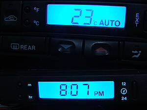
These results are with the LEDs that came out of the neo-wedge bases again. The light is pale, buy uniformity is excellent (much better to the naked eye), and this is just using the stock resisor that came with the neo-wedges. I will try some other resistances, and see which is best.

Last edited by Oubadah; 04-19-2012 at 04:16 AM.
#5
07-04-2010, 02:40 PM
#6
07-05-2010, 02:33 AM
It's difficult to explain some of the custom fittings in the X300. I'll take some pictures for you guys in a few hours. So far, I've managed to successfully substitute all the interior backlights in the car except for the panel behind the wheel. I'm still perfecting my dimming/diffusion techniques - in fact, now that I know the dimming circuitry works on LEDs, I might be able to get away with simply frosting the surfaces, rather than painting them. This would be excellent as painting takes a lot of time, and it's hard to get good uniformity.
#7
07-05-2010, 04:46 AM
Veteran Member
Hi, you really should post up a series of pics of the work you are doing here. Both before the change and after. Together with your painting/frosting the LEDs.
As regards some of the more difficult to explain custom fittings, you could simply post a pic of the unit in question and say where it goes.
We are always on the look out for good DIY modifications to include in the FAQs.
As regards taking the door apart I don't have an X300, but with an XJ40 it is a matter of 10 mins.
Trending Topics
#8
07-05-2010, 05:41 AM

Clock Module:
1) T4 Neo-Wedge (must be White)
2) T4 Neo-Wedge
3) N/A
4) T4 Neo-Wedge
5) T4 Neo-Wedge
6) N/A
7) T4 Neo-Wedge

Air Con Module:
1) T3 Neo-Wedge
2) T3 Neo-Wedge
3) T3 Neo-Wedge
4) T4 Neo-Wedge
5) T3 Neo-Wedge (must be White)
6) T4 Neo-Wedge
7) T3 Neo-Wedge
8) T3 Neo-Wedge
9) T3 Neo-Wedge
10) T3 Neo-Wedge
The stock incandescents have blue rubber caps over them, resulting in a greenish light. I chose to go with spark blue LED replacements, but there were green, red, amber etc. available.
There are basically two sizes of twist lock neo-wedge socket used in the car:
For the larger neo-wedge lights, the X300 uses standard T4 fittings (base diameter 10mm). The smaller neo-wedge fittings are close to T3 (base diameter 8mm), but actually measure 8.70mm. T3 fittings can still be used though.
The neo-wedge fittings used in the centre roof console are somewhere in between. There is no fitting available between T3 and T4, so I used T4. They were very tight, so I used a drill bit to widen the sockets in the PCB just a fraction, now they fit very well. It is important to note that these lights need to be quite short, so that they don't hit the insides of the buttons. I just sanded a mm or so off the lenses of my T4 LEDs.
Attachment 1
Back row from left: neo-wedge from roof console, small neo-wedge from aircon, large neowedge from aircon and clock.
Front row from left: Rubber colour caps from stock bulbs, T3 neowedge LED, T4 neowedge led.
The backlights for the window etc. buttons in the doors are mounted in a little rubber brick. The bulb fits into the centre of the brick, then the wires are fed up through holes on either side and folded over. The brick fits into a blue plastic clip, and the lot is mounted in a socket located under the wood trim. The socket has two contacts poking up, and they go into the holes in the rubber brick, touching the bulb wires (hope that makes sense):
Attachment 1
I wasn't sure what to do about these, but then I removed one of the T4 LEDs from it's neo-wedge base, and look:
Attachment 1
Including the components on either leg, it's about the size of one of the stock incandescent lights, so it fits into the rubber mount just fine.
The problem is that the door backlights actually take their light from the sides of the bulb, and refract it throught some translucent plastic. This is OK when using incandescents, because the basically illuminate 360 degrees. LEDs, on the other hand, fire straight out the end of the lens, so most of the light would just be shining down at nothing, rather than being carried through and illuminating the figures in the buttons. Fortunately, the light from the LED can be diffused by frosting the lens (I used 220 grit sandpaper). This ensures that some light finds it's way out the side of the LED.
The only issue I have now is that I can't find a way to access the backlight for the mirror controls in my drivers door. I've got the two for the window buttons, but one remains...
Last edited by Oubadah; 07-14-2010 at 05:35 AM.
#9
07-05-2010, 06:33 AM
Veteran member
Join Date: May 2008
Location: Great Mills, MD
Posts: 14,382
Likes: 0
Received 3,887 Likes
on
3,194 Posts
Oubadah, what you are seeing is normal. The new dimmer control units don't lower the voltage to the bulbs. They simply turn them on and off really quickly and then adjust the amount of off time to on time to give you the varying light intensity. This is what is causing your LEDs to change at the same rate as your standard incandescent bulbs. If you want me to get into more detail with this, let me know.
#10
07-05-2010, 07:12 AM
Oubadah, what you are seeing is normal. The new dimmer control units don't lower the voltage to the bulbs. They simply turn them on and off really quickly and then adjust the amount of off time to on time to give you the varying light intensity. This is what is causing your LEDs to change at the same rate as your standard incandescent bulbs. If you want me to get into more detail with this, let me know.
EDIT: I mean, why bother with anything other than voltage control when they obviously never intended to use anything other than incandescent lights? Either way, this is good news and I'm not complaining!

Frosted T4 LED in door mount. Tomorrow I'll compare this to the T3s I've already installed, and see which one works better.
Attachment 1
The door lights are the only ones I'll just frost - all the rest will have to be painted. Earlier today I tried putting frosted LEDs behind the air con LCD, and putting the dimmer knob to it's lowest possible setting, but the bulbs were still to bright for decent screen uniformity. The screen backlighting seems to have only two levels; very high, when the knob is clicked into it's home position, and high, when the knob is in any other position. Turning it down doesn't affect the LCD screen backlights, just the buttons.
Those lights fit into the sockets circled below:
Attachment 1
Last edited by Oubadah; 07-14-2010 at 05:36 AM.
#12
07-10-2010, 11:03 PM
I had initially dipped all my centre console neo-wedges in the enamel paint because I thought the results would be more uniform, but I've since discovered that brushing it on is more successful.
The T4 neowedge LEDs are not only physically larger, but they also use a brighter diode than the T3s, so I apply one coat to the T3s, and one full coat plus a second to just the end of the T4s. Will post photos tonight.
EDIT: These pictures are atrocious. I don't know why the lights look so uneven on camera.


Painted LEDs

The T4 neowedge LEDs are not only physically larger, but they also use a brighter diode than the T3s, so I apply one coat to the T3s, and one full coat plus a second to just the end of the T4s. Will post photos tonight.
EDIT: These pictures are atrocious. I don't know why the lights look so uneven on camera.

Painted LEDs
Last edited by Oubadah; 07-11-2010 at 07:02 PM.
#14
07-11-2010, 07:06 PM
See above. Added a photo of stock lighting for reference - I guess my LEDs aren't too bad, because the stock lights look even more uneven. (note: green lights appear much dimmer because they were taken with more ambient light)
I've sent my clock to modulemaster for repair (once and for all, hopefully), which is why it didn't feature in my photo.
EDIT:
Found the little bugger. Yes, you have to take apart the whole goddamn door to get to it:
Attachment 1
2 = The mystery mirror control backlight (why didn't they make it accessable like the other two/three)
3 = Contacts for backlighting whatever extra controls are included in high spec cars. This has an access hole included in such cars (mine just has the depression where the hole would be)
1 = I wonder what this thing is??? it certainly isn't an active backlight...
reverse:
Attachment 1
What a lot of circuitry!
I've sent my clock to modulemaster for repair (once and for all, hopefully), which is why it didn't feature in my photo.
EDIT:
The only issue I have now is that I can't find a way to access the backlight for the mirror controls in my drivers door. I've got the two for the window buttons, but one remains...
Attachment 1
2 = The mystery mirror control backlight (why didn't they make it accessable like the other two/three)
3 = Contacts for backlighting whatever extra controls are included in high spec cars. This has an access hole included in such cars (mine just has the depression where the hole would be)
1 = I wonder what this thing is??? it certainly isn't an active backlight...
reverse:
Attachment 1
What a lot of circuitry!
Last edited by Oubadah; 07-12-2010 at 12:19 AM.
#17
07-12-2010, 05:50 AM
When I finish with all this lighting, I might try to re-arrange this thread into more of a chronological guide...
For now here is some more detail on that mirror light.
If you want to go to the effort of replacing the hidden mirror backlight, you'll need to remove the interior trim panel from the door (a drama in itself), then disassemble the trim panel to acces the switch box.
1) Once you have removed the black switch box from the door, turn it over and there should be a single screw right in the centre (it might be concealed by a sticker). Remove the screw.
2) The casing will still be held together by a plastic clip at either end, so gently lift them to open it.
3) Unclip the two ribbon cables by lifting the socket clamp out and up.
4) The PCB that the ribbon cables were connected to is held down by two screws at one end. Remove them.
5) Now you should be able to lift out the PCB with it's rubber cladding. Do this carefully as there are lots of tiny plastic parts beneith.
The mirror backlight will now be accessible.
If you're installing an LED, remember it can only work one way around. Polarity is as pictured below, although It would be wise to connect the switchbox to the car and double check prior to reassembling the door:

By the way, you can tell the polarity of an LED bulb by looking at it's structure inside the lens. The cathode is the larger part and is the negative side of the LED. The smaller anode is positive:

Of course if you're coating the lenses with paint or anything, you wont be able to see this structure, so it's a good idea to mark the positive side of the base with vivid or something before you make any modifications.
For now here is some more detail on that mirror light.
If you want to go to the effort of replacing the hidden mirror backlight, you'll need to remove the interior trim panel from the door (a drama in itself), then disassemble the trim panel to acces the switch box.
1) Once you have removed the black switch box from the door, turn it over and there should be a single screw right in the centre (it might be concealed by a sticker). Remove the screw.
2) The casing will still be held together by a plastic clip at either end, so gently lift them to open it.
3) Unclip the two ribbon cables by lifting the socket clamp out and up.
4) The PCB that the ribbon cables were connected to is held down by two screws at one end. Remove them.
5) Now you should be able to lift out the PCB with it's rubber cladding. Do this carefully as there are lots of tiny plastic parts beneith.
The mirror backlight will now be accessible.
If you're installing an LED, remember it can only work one way around. Polarity is as pictured below, although It would be wise to connect the switchbox to the car and double check prior to reassembling the door:
By the way, you can tell the polarity of an LED bulb by looking at it's structure inside the lens. The cathode is the larger part and is the negative side of the LED. The smaller anode is positive:
Of course if you're coating the lenses with paint or anything, you wont be able to see this structure, so it's a good idea to mark the positive side of the base with vivid or something before you make any modifications.
Last edited by Oubadah; 07-12-2010 at 05:55 AM.
#18
07-12-2010, 08:20 AM


Veteran Member
Join Date: Mar 2008
Location: Pacific Northwest USA
Posts: 24,823
Received 10,873 Likes
on
7,151 Posts
I admire your patience. I had a couple of a/c panel and clock panel bulbs burn out some time back. Annoyed at the stupid expensive price of genuine Jag replacements I tried various aftermarket bulbs (LED and incandescent) and eventually gave up trying to get the right color and brightness. My hat's off to you for sticking with it.
Your pics of the opened-up window control are very helpful to me for another reason: the tiny switch to slect "left" or "right" for the mirrow adjustment is broken on mine. Now that it's clear that the control can be sucessfully opened up for servicing I'm pretty sure I can fix it....and thanks to your pics I have a good idea of what I'm getting into
Cheers
DD
#19
07-14-2010, 01:42 AM
After my most recent layer of paint, I can see that the colour of the LEDs is going to be affected if I put on any more. They're still a little brighter than the stock lights and the LED's I put in my doors.
I guess I shouldn't be so **** about brightness consistency, as the stock lighting was pretty patchy.
I guess I shouldn't be so **** about brightness consistency, as the stock lighting was pretty patchy.
#20
07-14-2010, 07:21 PM
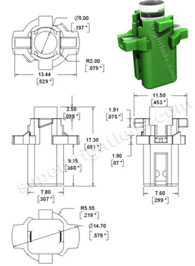
Are the X300 and XJ40 gauge cluster lights the same? If so, these LED ones are looking pretty promising:

Source: Super Bright LEDs (they even have a 3D view feature)
XJ40 stock gauge cluster lights:

Source: XJ40.com
Source: Super Bright LEDs (they even have a 3D view feature)
XJ40 stock gauge cluster lights:
Source: XJ40.com
Last edited by Oubadah; 07-14-2010 at 07:26 PM.