What?! LED Backlights Dimming.
#21
 07-17-2010, 10:39 PM

I used four of these: http://ledbulbs.co.nz/product_info.p...f3b31556a6aced for my foward ceiling lights. I did a pretty shoddy job of installing them (butchered the stock mount, and hot glued). they look great from the outside though, and the extra light output is awesome. I wanted a cleaner solution for the rear interior lights though...
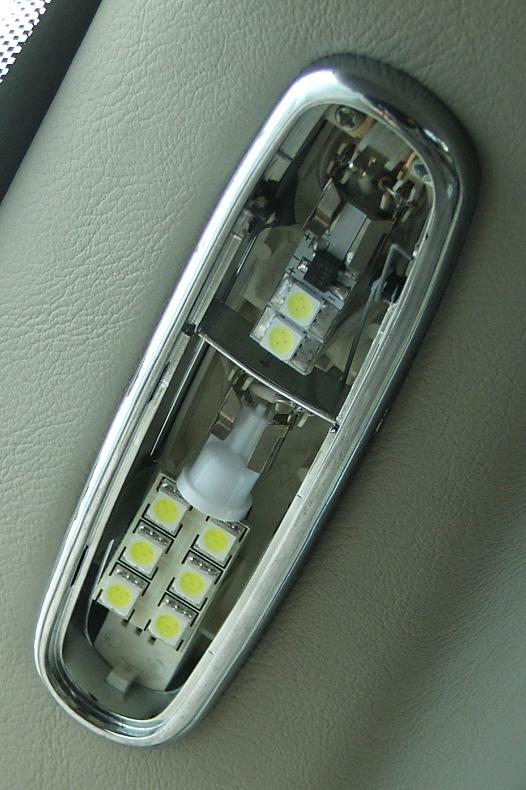
Rear interior lighting: SuperBrightLEDs had some wedge based flank-mount PCBs with six chips (each chip has three diodes), but they were too big for the map lights. I ended up getting them for the main lights, and these for the map lights:
http://www.bl-led.com.au/store/index...&cPath=5_20_46
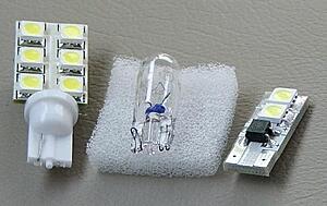

Unfortunately upper ones are a different colour to the lower ones. The SBLED ones are a purer white, while the BLLED ones are colder (more like the ones I installed in the front to my cabin. I don't suppose it's a big deal though.
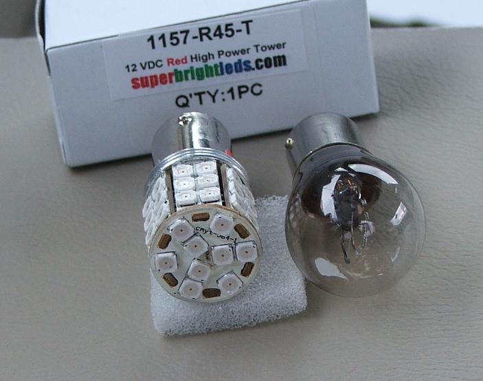
I also got a pair of dual-inensity brake lights from SBLED. They weren't cheap though...
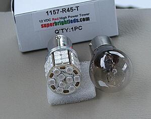
They're definitely brighter than the incandescents, especially on 'high beam'. The light distribution behind the plastic lens is better too - less blotchy. I tried to take a night photo, but the difference didn't show.
By the way, I ordered another batch of neowedge backlights and now experimenting with using resistors to dim them (couldn't leave well enough alone). Will post results.
Rear interior lighting: SuperBrightLEDs had some wedge based flank-mount PCBs with six chips (each chip has three diodes), but they were too big for the map lights. I ended up getting them for the main lights, and these for the map lights:
http://www.bl-led.com.au/store/index...&cPath=5_20_46

Unfortunately upper ones are a different colour to the lower ones. The SBLED ones are a purer white, while the BLLED ones are colder (more like the ones I installed in the front to my cabin. I don't suppose it's a big deal though.
I also got a pair of dual-inensity brake lights from SBLED. They weren't cheap though...
They're definitely brighter than the incandescents, especially on 'high beam'. The light distribution behind the plastic lens is better too - less blotchy. I tried to take a night photo, but the difference didn't show.
By the way, I ordered another batch of neowedge backlights and now experimenting with using resistors to dim them (couldn't leave well enough alone). Will post results.
Last edited by Oubadah; 07-18-2010 at 06:53 AM.
#22
07-19-2010, 03:58 AM
Now I'm getting somewhere:

I removed the resistor from one of my neowedge LEDs and I've been using a decade box to test various resistances on it for dimming. Here is a frosted LED with 10000 ohms of resistance beside one of the stock incandescents:
Attachment 1
The camera is a bit deceptive again (the led blue has more 'impact'), but that LED is just about spot on stock intensity. No more painting! Just compare it to my other photos with LEDs installed.
So now I'll just get a few resistors around 10000 ohm and install them properly behind the LCD screens (these are the critical things to test). Once I get perfect uniformity, I'll do a whole batch.
I multimetered the neowedge sockets while the module was connected to the car and got 11.3v in standby and 14.30 running, so now I'm doing all my testing at 14v.
Here's another benifit to dimming the leds with resistors: less load on them, so longer life should result.
I enlarged all the smaller neowedge sockets in the air-con module. As I said before, Jaguar's smaller neowedge sockets measure somewhere between the T3 and T4 standards, and while T3s fit well, T4s fit even better once the sockets have been slightly enlarged. A 5/64 drill bit works well - just twist it carefully to shave off the excess PCB. Using only T4s also gives you a better shot at decent uniformity.
I disassembled the module further to do this, so here is a pic. Notice the heat residue in the LCD backlight reflector.
Attachment 1
Last edited by Oubadah; 07-19-2010 at 07:03 AM.
#23
07-29-2010, 09:07 AM
I had two X300 clocks repaired by ModuleMaster recently, and their repair includes LED backlighting for the LCD screen. Of course, I wanted to mange my own backlighting for my car, so I told them to exclude the procedure from my clock. I let them modify the other clock though, and I'm glad I did because their strategy might be the best so far! They simply mounted their LEDs at 90 degrees so they weren't pointing directly at the screen (why didn't I think of that?). The result is an incredibly even distribution of light across the screen, and I've been able to re-create this in my clock and air-con screens.
There are some downsides:
- The colour of the light is whitened because all of it is refracting through, or reflecting off the white plastic structure behind the screen.
- A 'drop in' solution is virtually impossible. You have to solder the LEDs directly to the PCB.
I think it's worth it though.
You need to solder the resistor and diode to the LED at 90 degrees, and then bend the legs so that they'll sit on the contact solder pads around the neo-wedge sockets, paying attention to polarity:
Attachment 1
Positioning of legs for air-con screen.
Attachment 1
Positioning of legs for clock screen.
Then solder them in place, both facing inward:
Attachment 1
Once they are soldered in you can gently reposition them to make sure they are parallel with the screen:
Attachment 1
These results are with the LEDs that came out of the neo-wedge bases again. The light is pale, buy uniformity is excellent (much better to the naked eye), and this is just using the stock resisor that came with the neo-wedges. I will try some other resistances, and see which is best.

Last edited by Oubadah; 07-30-2010 at 04:53 AM.
#24
07-30-2010, 08:18 AM
Dimming Neo-Wedge LEDs - Increased Resistance and Frosting
This method produces a much more predictable result that the painting method, and should hopefully increase LED lifespan. I asked a few suppliers if they'd sell me neo-wedge LEDs with 10k resistors pre-installed, but none would comply.
A) Unwind the two wires and straighten them with pliers (don't bend them around too much or they will weaken and break):
Attachment 1
B) Gently work the LED out of the plastic base. You'll probably have to rock it from side-to-side a couple of times to break the glue. The stock resistor and/or the glass-cased diode might become disconnected in the process:
Attachment 1
NOTE: There was some overzealous glueing evident in a few of the neo-wedge LEDs I purchased from superbrightleds.com, which made it impossible to extract the LED and it's components without destroying the base. For this reason, it's important to buy extras.
C) Remove any glue from the plastic base, LED or other components.
D) De-solder the stock resistor, and cut the new one to match:
Attachment 1
I found a pair of locking surgical forceps very useful for holding this still during soldering.
NOTE: Resistors are bipolar, so it doesn't matter which end is connected to the LED.
E) Attach the new resistor, and re-attach the diode if it came off.
Attachment 1
NOTE: The resistor needs to be on the positive side of the LED and the diode on the negative, make sure they don't get mixed up.
F) 'Frost' the entire LED by sanding it with a fine sandpaper until it becomes translucent.
G) Re-install the LED into it's Plastic base.
IMPORTANT! To prevent conflicts with buttons:
- Neo-wedge lights to be used in the ceiling console must be shortened. Just sand ~1.5mm off the end of the LEDs during the frosting process. Make sure you don't sand through to the metal parts inside the LED.
Attachment 1
- Neo-wedge lights to be used in the clock module must have their plastic bases shortened. Slice ~2mm off the top of the base with a sharp knife before re-installing the LED.
Attachment 1
After some trials, 10k resistors appeared best for general use, while I used 8.2k for white LEDs and screen backlighting. Screen backlights were soldered directly to the PCB and positioned at 90� facing inwards. NOTE: Using the stock resistor for the 90� screen backlights produces better uniformity and distribution for daytime use, but in my opinion was too bright for night use. With the 8.2k resistors I eventually decided to use, the screens better match the buttons at night, but appear more 'blotchy' in broad daylight.
Clock Module:
1) T4 Neo-Wedge.........8.2k
2) T4 Neo-Wedge .........10k
3
4) 90� Soldered..............8.2k
5) 90� Soldered..............8.2k
6)
7) T4 Neo-Wedge .........10k
Air-con Module:
1) T4 Neo-Wedge .........10k
2) T4 Neo-Wedge .........10k
3) T4 Neo-Wedge .........10k
4) 90� Soldered..............8.2k
5) T4 Neo-Wedge..........8.2k
6) 90� Soldered..............8.2k
7) T4 Neo-Wedge .........10k
8) T4 Neo-Wedge .........10k
9) T4 Neo-Wedge .........10k
10) T4 Neo-Wedge ...... 10k
Ceiling Console:
1) T4 Neo-Wedge .........10k
2) T4 Neo-Wedge .........10k
3) T4 Neo-Wedge .........10k
NOTE: I didn't increase the resistances to the door backlights, as they have a hard enough time distributing enough light with the stock resistor.
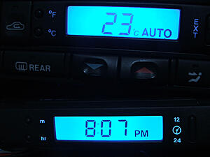
Sorry about the poor focus, my camera's screen is barely larger than a square inch. As always, the lights looked much better in real life:
Attachment 1
Heres one for comparison to my aftermarket stereo's backlights, and including J-Gate:

A Note on 'J-Gate' Lighting:
I opened everything up expecting to find separate incandescents for each stick position. But Jaguar have actually usedtiny little LEDs as shown here:
Attachment 1
So the only light to replace is the incandescent that lights up the whole thing, and this can be accessed by simply removing the three trim rings the go around the J-Gate. The stock light is a mini-wedge incandescent with a 5mm base. There are plenty of LED replacement options available. I used this: http://ledbulbs.co.nz/product_info.p...d42717f3d1ad80
I also tried the SMD LED type, but it was far too bright.
[Note on removing and installing J-Gate bulbs: It's really easy to drop the damn things, so make sure you grip them firmly with something. I dropped a little glass bulb down into the shifter mechanism, never to be seen again. I hope it doesn't smash down there and jam anything!]
You will notice that the upper part of the J-Gate is not very well illuminated (between P and R). Well that seems pretty much impossible to light uniformly, even with the stock solution.
(Original post updated)
This method produces a much more predictable result that the painting method, and should hopefully increase LED lifespan. I asked a few suppliers if they'd sell me neo-wedge LEDs with 10k resistors pre-installed, but none would comply.
A) Unwind the two wires and straighten them with pliers (don't bend them around too much or they will weaken and break):
Attachment 1
B) Gently work the LED out of the plastic base. You'll probably have to rock it from side-to-side a couple of times to break the glue. The stock resistor and/or the glass-cased diode might become disconnected in the process:
Attachment 1
NOTE: There was some overzealous glueing evident in a few of the neo-wedge LEDs I purchased from superbrightleds.com, which made it impossible to extract the LED and it's components without destroying the base. For this reason, it's important to buy extras.
C) Remove any glue from the plastic base, LED or other components.
D) De-solder the stock resistor, and cut the new one to match:
Attachment 1
I found a pair of locking surgical forceps very useful for holding this still during soldering.
NOTE: Resistors are bipolar, so it doesn't matter which end is connected to the LED.
E) Attach the new resistor, and re-attach the diode if it came off.
Attachment 1
NOTE: The resistor needs to be on the positive side of the LED and the diode on the negative, make sure they don't get mixed up.
F) 'Frost' the entire LED by sanding it with a fine sandpaper until it becomes translucent.
G) Re-install the LED into it's Plastic base.
IMPORTANT! To prevent conflicts with buttons:
- Neo-wedge lights to be used in the ceiling console must be shortened. Just sand ~1.5mm off the end of the LEDs during the frosting process. Make sure you don't sand through to the metal parts inside the LED.
Attachment 1
- Neo-wedge lights to be used in the clock module must have their plastic bases shortened. Slice ~2mm off the top of the base with a sharp knife before re-installing the LED.
Attachment 1
After some trials, 10k resistors appeared best for general use, while I used 8.2k for white LEDs and screen backlighting. Screen backlights were soldered directly to the PCB and positioned at 90� facing inwards. NOTE: Using the stock resistor for the 90� screen backlights produces better uniformity and distribution for daytime use, but in my opinion was too bright for night use. With the 8.2k resistors I eventually decided to use, the screens better match the buttons at night, but appear more 'blotchy' in broad daylight.
Clock Module:
1) T4 Neo-Wedge.........8.2k
2) T4 Neo-Wedge .........10k
3
4) 90� Soldered..............8.2k
5) 90� Soldered..............8.2k
6)
7) T4 Neo-Wedge .........10k
Air-con Module:
1) T4 Neo-Wedge .........10k
2) T4 Neo-Wedge .........10k
3) T4 Neo-Wedge .........10k
4) 90� Soldered..............8.2k
5) T4 Neo-Wedge..........8.2k
6) 90� Soldered..............8.2k
7) T4 Neo-Wedge .........10k
8) T4 Neo-Wedge .........10k
9) T4 Neo-Wedge .........10k
10) T4 Neo-Wedge ...... 10k
Ceiling Console:
1) T4 Neo-Wedge .........10k
2) T4 Neo-Wedge .........10k
3) T4 Neo-Wedge .........10k
NOTE: I didn't increase the resistances to the door backlights, as they have a hard enough time distributing enough light with the stock resistor.
Sorry about the poor focus, my camera's screen is barely larger than a square inch. As always, the lights looked much better in real life:
Attachment 1
Heres one for comparison to my aftermarket stereo's backlights, and including J-Gate:
A Note on 'J-Gate' Lighting:
I opened everything up expecting to find separate incandescents for each stick position. But Jaguar have actually usedtiny little LEDs as shown here:
Attachment 1
So the only light to replace is the incandescent that lights up the whole thing, and this can be accessed by simply removing the three trim rings the go around the J-Gate. The stock light is a mini-wedge incandescent with a 5mm base. There are plenty of LED replacement options available. I used this: http://ledbulbs.co.nz/product_info.p...d42717f3d1ad80
I also tried the SMD LED type, but it was far too bright.
[Note on removing and installing J-Gate bulbs: It's really easy to drop the damn things, so make sure you grip them firmly with something. I dropped a little glass bulb down into the shifter mechanism, never to be seen again. I hope it doesn't smash down there and jam anything!]
You will notice that the upper part of the J-Gate is not very well illuminated (between P and R). Well that seems pretty much impossible to light uniformly, even with the stock solution.
(Original post updated)
Last edited by Oubadah; 08-24-2010 at 03:02 AM.
#25
08-24-2010, 08:36 AM
That is so awesome! I love it! I've been working on cleaning up the S-Type FAQ. Cadillac was giving me some advice on it. I mentioned wanting to do something like this eventually and he mentioned to check your post out. I'm not sure how different the lighting components are on the S-Type. I'll have to check it out later when I have time. I would really love to do something with the instrument panel. It looks dated. I also really don't like the monochrome green LCD displays. Would possibly like to remove the ones that are there and replace with ones that show the blue/purple light.
#26
09-12-2010, 02:46 AM
Senior Member
Awesome write-up, Thanks for sharing. I had already done my clock with LED before seeing this post. I did exactly what you had mentioned. Resistors and laid it sideways. Looks really nice. Now need to do the rest as you have. 
And the source for bulbs, WOW. I built my own from Radio Shack, but this will be my new source. Prices are reasonable too. Before doing LED, I Paid $12 for a replacement bulb for my temp gauge. ONE Bulb, YUK!
And the source for bulbs, WOW. I built my own from Radio Shack, but this will be my new source. Prices are reasonable too. Before doing LED, I Paid $12 for a replacement bulb for my temp gauge. ONE Bulb, YUK!
Last edited by SuperSport; 09-12-2010 at 02:51 AM.
#27
09-16-2010, 01:31 PM
Veteran Member
@Oubadah
The X308 climate switchpack is very similar to the X300. I did an LED conversion a few months ago, just completed the reshell of the car I updated led's to so finally can see the difference.
I must say finding a perfect lit effect in your car is downright admirable, the work involved and the time it's taken.
I just screwed in the t3's and T4's. I went an alternative route instead of relieving some material on the PCB I shaved off the plastic around the neowedges with a sharp knife. I also found shaving the backs of the buttons, instead of sanding down the bulbs to get clearance.
I think mine are a wee bit too bright, how about a rheostat with more range, could it be a fix? You've dealt with the screen backlighting in a smart way. I might solder some of those resistors and do the 90 degree trick in the future. I've also found why you stress temp up and down bulb must be white, I fitted a green one and the up button isn't lit.
Well done man!
#28
09-19-2010, 06:15 PM
@Oubadah
The X308 climate switchpack is very similar to the X300. I did an LED conversion a few months ago, just completed the reshell of the car I updated led's to so finally can see the difference.
I must say finding a perfect lit effect in your car is downright admirable, the work involved and the time it's taken.
I just screwed in the t3's and T4's. I went an alternative route instead of relieving some material on the PCB I shaved off the plastic around the neowedges with a sharp knife. I also found shaving the backs of the buttons, instead of sanding down the bulbs to get clearance.
I think mine are a wee bit too bright, how about a rheostat with more range, could it be a fix? You've dealt with the screen backlighting in a smart way. I might solder some of those resistors and do the 90 degree trick in the future. I've also found why you stress temp up and down bulb must be white, I fitted a green one and the up button isn't lit.
Well done man!
The X308 climate switchpack is very similar to the X300. I did an LED conversion a few months ago, just completed the reshell of the car I updated led's to so finally can see the difference.
I must say finding a perfect lit effect in your car is downright admirable, the work involved and the time it's taken.
I just screwed in the t3's and T4's. I went an alternative route instead of relieving some material on the PCB I shaved off the plastic around the neowedges with a sharp knife. I also found shaving the backs of the buttons, instead of sanding down the bulbs to get clearance.
I think mine are a wee bit too bright, how about a rheostat with more range, could it be a fix? You've dealt with the screen backlighting in a smart way. I might solder some of those resistors and do the 90 degree trick in the future. I've also found why you stress temp up and down bulb must be white, I fitted a green one and the up button isn't lit.
Well done man!


#31
11-23-2010, 01:03 AM

Junior Member
Join Date: Nov 2010
Location: Seattle
Posts: 10
Likes: 0
Received 0 Likes
on
0 Posts
#32
11-24-2010, 05:45 PM

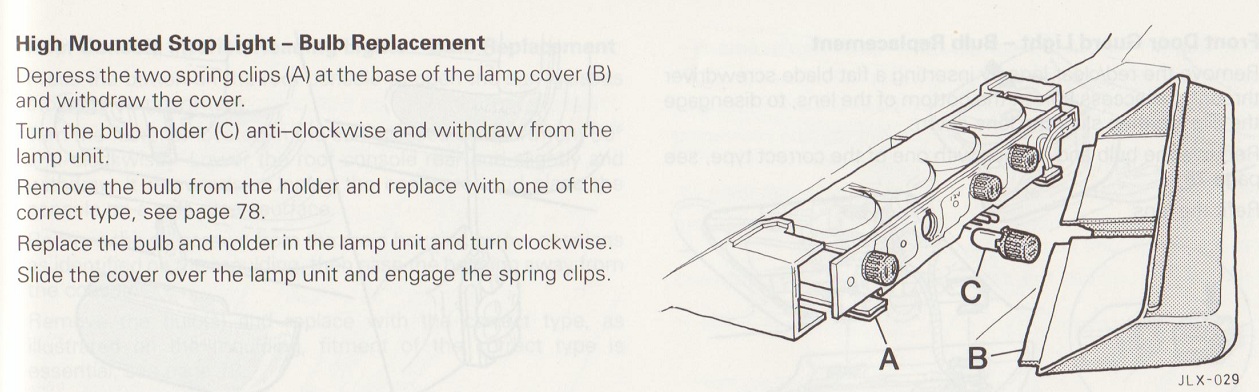
The manual says to use the 5W type (as opposed to 6W):

#33
11-07-2012, 03:52 AM

Junior Member
Are the X300 and XJ40 gauge cluster lights the same? If so, these LED ones are looking pretty promising:

Source: Super Bright LEDs (they even have a 3D view feature)
XJ40 stock gauge cluster lights:

Source: XJ40.com
Source: Super Bright LEDs (they even have a 3D view feature)
XJ40 stock gauge cluster lights:
Source: XJ40.com
Im sure that these jaguar bulbs are same in x300, and if somebody could measure the white one and the brown one it could be interesting to find a led equivalent in B8.3d B8.4d B8.5d or B8.7d
Who has the gen one and can take measures ?
I guess can be useful for everybody

Ciao !
#34
04-22-2013, 07:58 AM

Hi
I�m very keen to do what you have done, and your thread is really good.
But I wonder how you connect the power supply to the AC and clockmodule for testing outside of the car.
Could you possibly post a picture or a drawing.
That would be a great help, for an exited but total rookie.
Best
Christian
I�m very keen to do what you have done, and your thread is really good.
But I wonder how you connect the power supply to the AC and clockmodule for testing outside of the car.
Could you possibly post a picture or a drawing.
That would be a great help, for an exited but total rookie.
Best
Christian
#35
05-02-2013, 04:46 AM
Hi
I�m very keen to do what you have done, and your thread is really good.
But I wonder how you connect the power supply to the AC and clockmodule for testing outside of the car.
Could you possibly post a picture or a drawing.
That would be a great help, for an exited but total rookie.
Best
Christian
I�m very keen to do what you have done, and your thread is really good.
But I wonder how you connect the power supply to the AC and clockmodule for testing outside of the car.
Could you possibly post a picture or a drawing.
That would be a great help, for an exited but total rookie.
Best
Christian
#36
05-05-2013, 05:13 AM
Hi
Ok, on ones of your pictures it looks like you had the AC panel going on the bench.
Soldered for the first time yesterday, and managed to put in new resistors and connect to the pcb. Nice and uniform lighting, will do the clock next.
Thx again, you thread is what makes the internet so fantastic, very impressed,
the order from BL led toke less than two weeks to arrive.
Keep posting.
Christian jag lover from the south of Sweden.
#37
05-27-2013, 08:30 AM
Have been working on the clock and AC modules, I used the same bulbs as you did, behind the displays that is.
All though to my eye 13K was bright enough for me, not used to the light as you are in sunny NZ.
Now I would like the radio display to match the two others, how complicated is it to open the radio and change the bulbs behind the display?
I have the original radio fitted to the x300.
/Christian
All though to my eye 13K was bright enough for me, not used to the light as you are in sunny NZ.
Now I would like the radio display to match the two others, how complicated is it to open the radio and change the bulbs behind the display?
I have the original radio fitted to the x300.
/Christian
#38
06-29-2013, 05:16 AM

Hi there,
as my odometer bulbs died a painful death, I decided to try changing to blue LEDs. I ordered 4 x B8.7D Twist Lock 1-LED (Blue) from BL LED in Australia to play around. The Odo looks stunning, so I have ordered another 14 LEDs to "upgrade" all the Rest. As soon as the work is done, I will post photos & a description of the work.
Julian