When you click on links to various merchants on this site and make a purchase, this can result in this site earning a commission. Affiliate programs and affiliations include, but are not limited to, the eBay Partner Network.
If you place your hand on the ignition switch key barrel area as you move the shift lever out of the park gate detent you should feel the key barrel lock solenoid, click saying the not in park switch is changing state or making
It is clicking, And now if I move the shift lever off the switch it starts, I've verified I have power to one side of the switch with button pressed with button released no power to switch Button Pressed Button released
Ok, Whatever is causing this has to do with the shifter gate assy, Ive check it 4 times, when I secure it the car won't start in park, when I move the shifter I can hear and feel the key lock solenoid, when I remove the gate assy the car starts, I checked and its not pinching the wire
Your meter reading on the not in park switch is correct along with key lock solenoid clicking
The BPM is putting out a feeler voltage and once the switch closes the feeler voltage goes to 0 ( grounded out )
The rotary position switch can be out of adjustment or intermittent not closing even with proper adjustment, but you gave it a cleaning which is all you can do other than installing it back in the original slotted screw holes
Adjusted rotary switch, It's starting over and over again, moved shifter around then back into park and it still starts, gonna take it off the jack stands and do a quick drive
As long as you move the shift lever out of the park detent and feel or hear the key lock solenoid click you have a change of state of the not in park switch without pulling things apart
This also confirms the current switch has the correct red button depression dimension to make and you have the correct NO or NC type connection with your wiring since it is swapable
It didn't get all the way up to freezing temperature today
on the anti - skid something easy to try is the brake switch which is involved
The brake switch is actually 2 switches in 1 package , 1 switch dedicated to the brake lights and the other to like the cruise control disconnect, traction control, and such
The brake switch socket is # 20 and is looking for a ground as you press the pedal
There is a superseded part # in a TSB
You can spin the wheels by hand in the correct direction of car fwd travel and the 4 / 2 color pairs of wires will show 1 volt ac on a meter
The sensors will read about 1300 ohms resistance and the 4 should be the same
You did clean the face of the sensors as fine metalic shavings can accumulate , this is different than the connector cleaning
Well I washed the car and was getting ready to take and get it smoked check, Fans don't work again, I have power at inertia switch jumpered no fans, have power at the freon switch & jumpered wires at radiator switch fans turn.swapped fan leads no turn pulled all fuses again
In the test you did for the fans you verified the fan control relay module , this does not test the switch itself
If it is hanging upside down, it will get water inside the module and ruin the power contacts inside so something to watch for
The proper module installation is the wires / connector is on the bottom, ask me how I know
The black color module on the later X308 does not work for the white color X300 model , a little bit of a difference
The TSB is to simply jumper the freon line low pressure switch and this will have the low fan mode on as soon as you start the car
Might try some in the tank fuel injector cleaner on the misfire
Is there a way to test fan control relay module? I have power across the TSB Mod, I have both fan modes when I jumper the radiator Thermostatic switch, I have power to the inertia switch but no fan when i jumper white wires,, I cannot find the ground your taking bout behind the left headlight but I cleaned both grounds on the firewall, Did my brand new relay module already take a dump? Plus the fans never turned on when it got hot and I feel no click in the relay when wife turns key to run.
The ground stud is under the engine air filter attached to the chassis frame rail that goes aft , there is one on the right side in same area , it will have about 4 small wires on it
White fan control relay module # LNA6702AA superceeed by LNA6702AB ? , the black one is a little bit different for the V8 powered X308
It is unlikely you will get high fan mode in the driveway with the system operating all hooked up and normal operating temp
With your 2 wire freon switch Jumper'd as the TSB you should have low fan mode regardless of the coolant temp
Editing
A direct test of the fan control relay module is to remove the 2 wire freon pressure switch jumper , this will be a no fan state of the original design
On the 3 wire radiator temp switch jumper one white wire to the black ground wire and you will get low fan mode
Remove the jumper and install on the other white wire to the same black ground wire and you will get high fan mode
these 2 last lines will confirm your ground stud is good
With the mod jumper on the 2 wire freon pressure switch you will have low fan mode with key in the run position and cold coolant temp
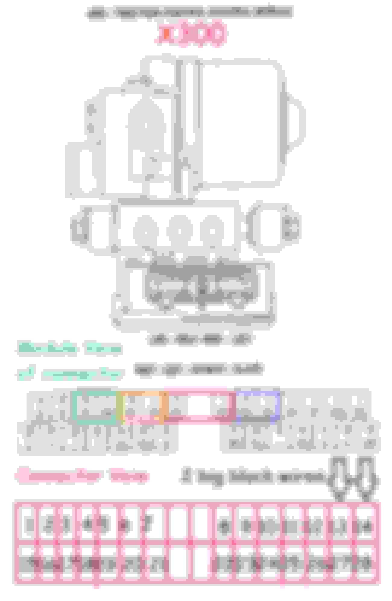
On the above pic :
Point 73 squire and 74 square share the same # 11 / 30 amp left engine bay fuse box fuse which is hot at all times directly wired to the battery cable
Point 76 square ..................# 17 / 30 amp left engine bay fuse box fuse that is hot at all times directly wired to the battery cable
The fan control relay module has it's own ground stud located .........LSG10L which is the same ground stud under the engine air filter
The ground stud is under the engine air filter attached to the chassis frame rail that goes aft , there is one on the right side in same area , it will have about 4 small wires on it
White fan control relay module # LNA6702AA superceeed by LNA6702AB ? , the black one is a little bit different for the V8 powered X308
It is unlikely you will get high fan mode in the driveway with the system operating all hooked up and normal operating temp
With your 2 wire freon switch Jumper'd as the TSB you should have low fan mode regardless of the coolant temp
Editing
A direct test of the fan control relay module is to remove the 2 wire freon pressure switch jumper , this will be a no fan state of the original design
On the 3 wire radiator temp switch jumper one white wire to the black ground wire and you will get low fan mode
Remove the jumper and install on the other white wire to the same black ground wire and you will get high fan mode
these 2 last lines will confirm your ground stud is good
With the mod jumper on the 2 wire freon pressure switch you will have low fan mode with key in the run position and cold coolant temp
On the above pic :
Point 73 squire and 74 square share the same # 11 / 30 amp left engine bay fuse box fuse which is hot at all times directly wired to the battery cable
Point 78 square ..................
Did 3 wire test fans operated like they should, I found the TSB lead on the relay plug, 6v key in off pos 0v in run pos, Feel no clicking when moving key off and on, Did not get any fan mode while idling in driveway

 11-12-2022, 01:06 PM