When you click on links to various merchants on this site and make a purchase, this can result in this site earning a commission. Affiliate programs and affiliations include, but are not limited to, the eBay Partner Network.
Since buying my XJR 1995 I’ve been having an intermittent no-start issue. I concluded it was immobilized and made this forum post
After not being able to solve the immobilizer issue after much troubleshooting I decided to spend a lot of money on a reprogrammed ecu where the immobilizer function was disabled. The seller told me that as long as I got the car cranking, (which I currently get by probing ground to the pin in the bpm that makes CEL light up) it would start up with this ecu since it would not need a signal from the security module to start fueling.
Sadly this was not the case. I still have the same symptoms, No fuel (no 5-second prime when turning the key) and no spark (I have tried with starter gas and checked visually for a spark.). The fuel pump and relay works, and the spark plugs are all new. All ignition relays work.
I am now wondering if I have multiple faults, not just the immobilizer. I have already tried bypassing the inertia switch and swapped the cps to a new one. The tacho still does not go up when cranking which from what I read means the cps is not working, since I definitely have a working sensor which I've checked by measuring the resistance between the pins, could it be something else?
Worth noting is that I also have the gearbox caution light in the dash and my OBD2 reader shows me code p1791 which I think has to do with throttle position.
Very thankful for any help. The Jag is just collecting dust now which is a shame.
Thank you for your quick response!
The RH engine bay fuse box relay clicks. The larger #5 relay RH does not. I tried swapping it with wiper relay which definitely works, still does not click.
So the relay is not getting power.
I'm not quite sure what you meant by "Your second # 1 fuel pump back on is the CKPS seeing engine rotation by way of the ECU being powered", could you clarify?
I have now checked the fuze and connector.
the fuze is fine. The connector does not look terrible, a bit of corosion but doesn't seem to be at the mentioned pin, i sprayed some electric cleaner and protectant and put it back. Whats the next troubleshooting step?
Put what you have back together and swap the small right engine bay fuse box relay for the left engine bay fuse box , this on the premise the small relay is getting the correct command and clicking closed but the power contacts inside are burnt and not conducting enough current to ultimately have the ECU to command the large # 9 relay closed
The small left engine bay fuse box relay only runs the car horn
I will get back today later for more Indepth information and checks
To get the engine running again in the short term place a jumper wire between socket 3 and 5 of the large # 9 relay socket but confirm is is the correct socket before hand by verifying the wire colors , The large relay sockets could have got mixed in position like on mine
Use heavy gauge wire with blade type wire ends for better connection
The auto parts store can help build up a jumper wire with the tool kit they keep behind the counter
You'll have to bring the key rotation to the starter position as normal for engine start
4 wire colors are .............
Socket 3 - Brown / Yellow , large wire
5 - Black / Light Green , large wire
2 - Brown / Orange , this is the one also in the Papa Indy 1 connector as socket # 6 and not 5 as earlier stated
I've now tried swapping the enginebay fusebox relays. And I have also tried putting jumper wire between 3 and 5 on which I assume you mean the #5 relay from your earlier image. The wires match.
The first power to the ECU is the right engine bay fuse box relay closing on key rotation
This puts power on fuse 10 , 12 , 14 , and 16 so check those to cover the bases
On the bottom surface of the fuse boxes is a ribbon connector attached to it you can check by removing the 2 mounting screws and flipping over
Once the 1st power is on the ECU , the ECU will command the large # 5 ECU control relay to close bringing power back into the ECU , power " sitting " on the injectors , and a few engine sensors
On the # 5 ECU control relay tug on the # 6 wire ( color Brown / Orange ) at the Papa Indy 1 connector and relay as corrosion can accure on the wire insertion side as well as the face that you inspected
These wires have an individual rubber seal plug to prevent water intrusion but ......
On my large # 5 ECU control relay the smaller control wire had it's insulation nicked for some reason and in practice if not protected can effect the relay closing
Today I checked fuse 10,12,14,16 they're all fine and have over 12,3V.
Then I started measuring the "brown orange" circuit. To my surprise pin 2 of the large #5 Relay had 12V+, which should close the relay switch, however, it does not click. But putting my jumper wire between 3 and 5 did no difference so I'm unsure what to check next.
The fuel pump still does not prime when turning the key, the pump is tested by jumping relay which works.
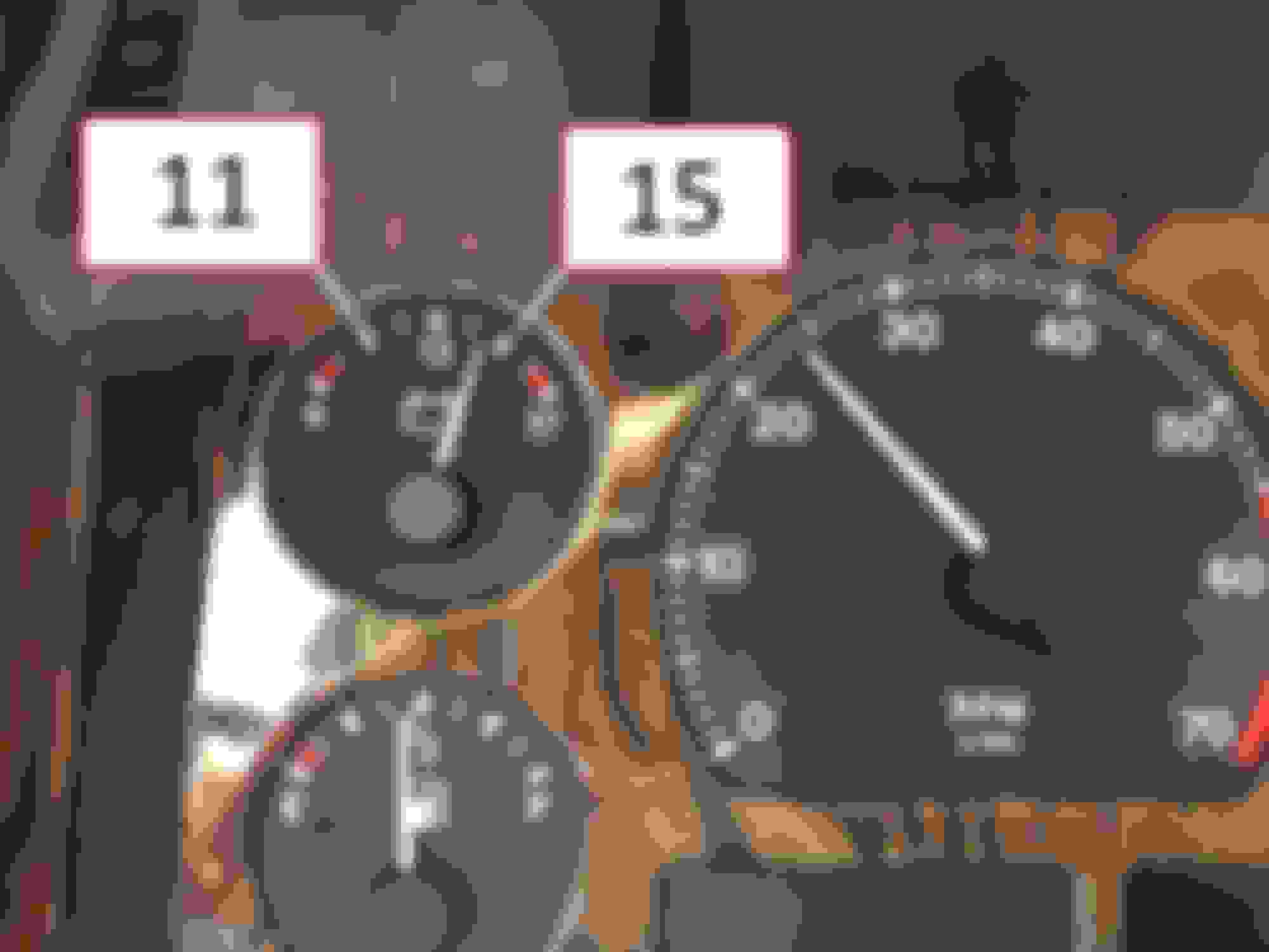
Regards to the voltage when cranking, the gauge in the clusters shows less than my voltage meter. The gauge shows way under eleven but when measuring directly on the battery it shows about 11.4-12V.
The cables in the connectors did not feel loose and I have not seen signs of corrosion.
To get the large relay # 5 ECU control relay to close the ECU provides a ground on socket # 1 allowing this relay's pulling coil control half to close allowing the other half to conduct the major power through the relay
But jumpering the power sockets 3 to 5 no help points to the smaller # 9 relay as the 1st power
Even though you have forced power to the high power side of the ECU the low power side of the ECU can still be missing
The smaller relay control half has power sitting on it as well from fuse Y and is provided a ground path through the ignition switch to car frame ground on pin 5 of the ignition switch connector near the barrel
If it comes to it the ignition switch removes from the key barrel so no new key needed
still no fuel or spark. I will attach a video when I'm cranking. As you will see the tacho does not move up, Since the CPS is fine I'm thinking maybe something might be wrong with the wiring to and from the sensor.
You will also see the gearbox caution-light light up. I will also attach a screenshot of the DTC code that pops up.
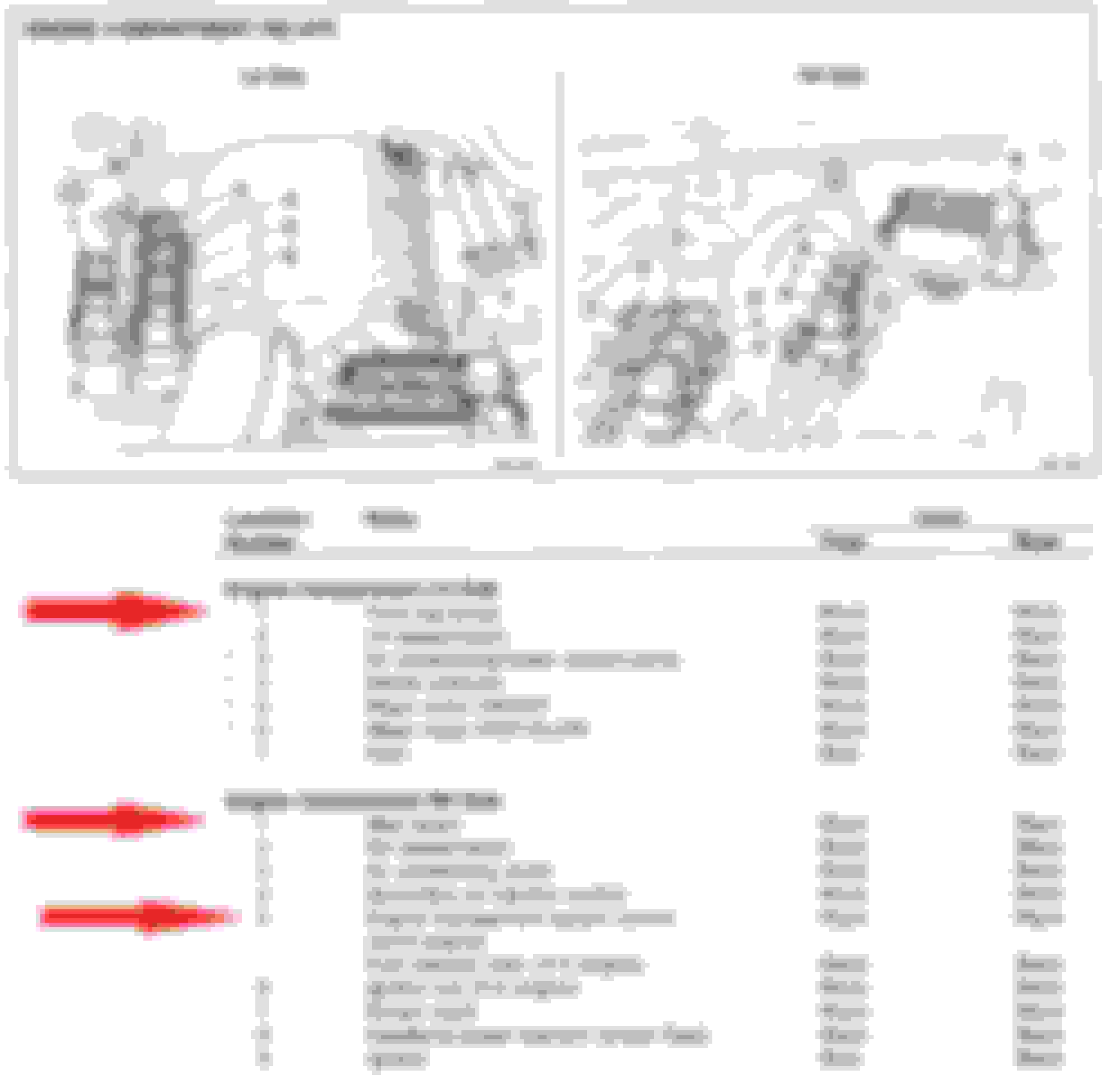
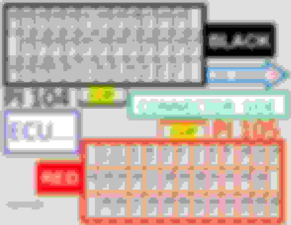
The crankshaft position sensor will read about 1300 ohms resistance as a fundamental reading and you can read it from the ECU connector at socket Black 23 ( white wire ) and Black 26 ( orange wire ) which will test those 2 wire runs which have no splices

 08-12-2023, 02:17 PM