5HP24 home repair on a BMW X5.
#21
 01-28-2012, 03:44 PM


#23
01-28-2012, 03:58 PM
The short answer is no. But if you remove the torque converter it helps. My son and I put it on the bench. Keep in mind mine has a transfer case on the back and a crossmember.
#24
01-28-2012, 04:29 PM
Veteran Member

#26
01-29-2012, 03:39 PM
Veteran Member
#27
01-30-2012, 05:41 PM
#28
01-31-2012, 04:56 PM
Hmmm, a bit of a roadblock, I'm afraid. I want to order an A drum, a bearing, and a modified pressure regulating valve. All three items are on backorder from ZF, according to Klaus.
I did look elsewhere (although I like CTSC and want to deal with them) I can find an A drum, but the other parts are harder.
Maybe it's a good time to relax and clean the garage while I wait.
I did look elsewhere (although I like CTSC and want to deal with them) I can find an A drum, but the other parts are harder.
Maybe it's a good time to relax and clean the garage while I wait.
#29
01-31-2012, 05:41 PM
I am putting together some posts on how to take apart your transmission.
DISCLAIMER: Please be aware that any problems, injuries, expenses, losses, etc are entirely your responsibility. I am doing this as a favour and a way to pay back for all the helpful posts I've used over the years.
Use the ZF manual! They are the experts, I am not, this is the first transmission I have ever touched.
I have a bit of time to kill and I am tired of getting dirty, so the valve body inspection can wait.
EDITING NOTE- I WILL UPLOAD PICTURES AND INSERT THEM AS READY, PLEASE CHECK BACK. Photobucket is a bit slow to upload.
Buy stuff- clean lint free rags or cloths. lots of plastic bags, boxes, etc. you'll want good lighting too. Normal metric handtools will be fine, but you will want a set of picks for removing o rings. A dead blow hammer will be handy too.
Buy a clutch spring compressor. You'll see what I used, but there's probably better ones out there.
Teardown notes.
1. They show a special tool to hold the torque converter in place while you pull it out of the car. I used some tie wraps, worked fine.
2. Pull the TC out straight and level and it just slides out. Be prepared for a bunch of fluid to pour all over the place.
3. The BMW crossmember is held on by one bolt.
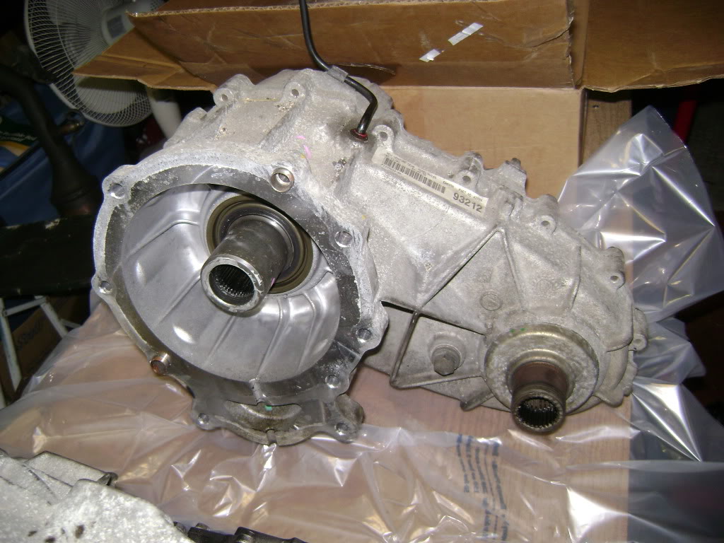
4. The transfer case is held on by a bunch of Torx external bolts. You'll need to loosen some of them by using a 3/8 wrench and a hammer. There is no way a socket and ratchet will fit on some of them. There is no gasket or fluid or anything, the whole case just comes off the back.
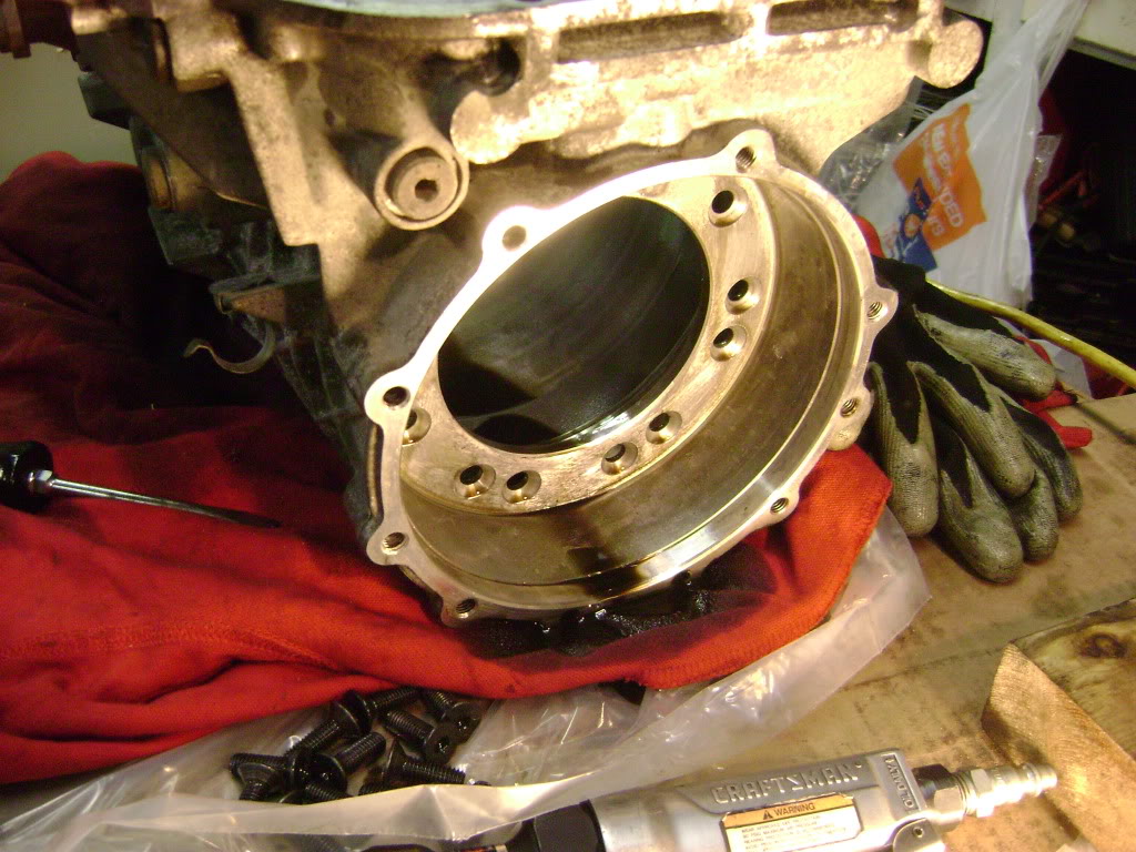
5. The output has an adaptor on it, that does have an o ring, and it will leak fluid. Once that's off, the rest of the transmission is just as it is shown in the ZF manual, easily available in pdf format online.

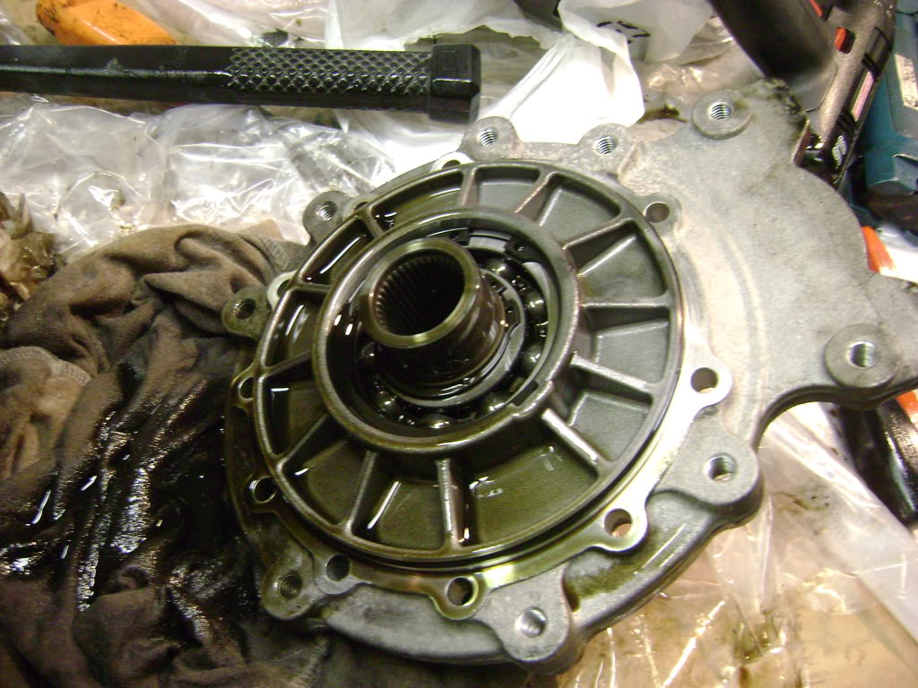
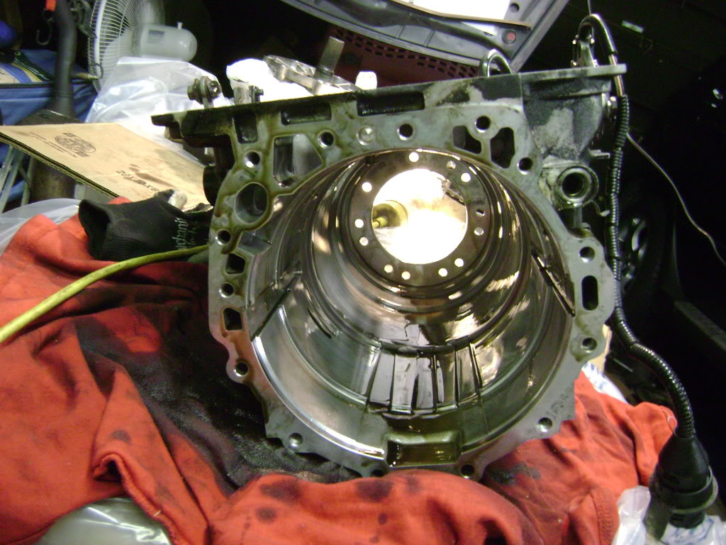
6. At the bell housing, remove the dark bolts and leave the light coloured ones in. A slight tap and the whole bell housing and pump assembly comes off at once.
More to come, as I think there's a limit to the number of pics per post.
DISCLAIMER: Please be aware that any problems, injuries, expenses, losses, etc are entirely your responsibility. I am doing this as a favour and a way to pay back for all the helpful posts I've used over the years.
Use the ZF manual! They are the experts, I am not, this is the first transmission I have ever touched.
I have a bit of time to kill and I am tired of getting dirty, so the valve body inspection can wait.
EDITING NOTE- I WILL UPLOAD PICTURES AND INSERT THEM AS READY, PLEASE CHECK BACK. Photobucket is a bit slow to upload.
Buy stuff- clean lint free rags or cloths. lots of plastic bags, boxes, etc. you'll want good lighting too. Normal metric handtools will be fine, but you will want a set of picks for removing o rings. A dead blow hammer will be handy too.
Buy a clutch spring compressor. You'll see what I used, but there's probably better ones out there.
Teardown notes.
1. They show a special tool to hold the torque converter in place while you pull it out of the car. I used some tie wraps, worked fine.
2. Pull the TC out straight and level and it just slides out. Be prepared for a bunch of fluid to pour all over the place.
3. The BMW crossmember is held on by one bolt.
4. The transfer case is held on by a bunch of Torx external bolts. You'll need to loosen some of them by using a 3/8 wrench and a hammer. There is no way a socket and ratchet will fit on some of them. There is no gasket or fluid or anything, the whole case just comes off the back.
5. The output has an adaptor on it, that does have an o ring, and it will leak fluid. Once that's off, the rest of the transmission is just as it is shown in the ZF manual, easily available in pdf format online.
6. At the bell housing, remove the dark bolts and leave the light coloured ones in. A slight tap and the whole bell housing and pump assembly comes off at once.
More to come, as I think there's a limit to the number of pics per post.
Last edited by avt007; 01-31-2012 at 07:04 PM.
#30
01-31-2012, 06:00 PM
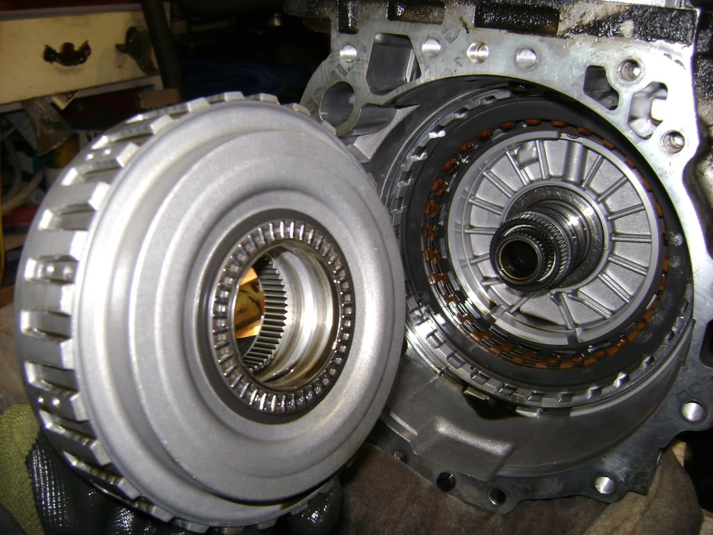
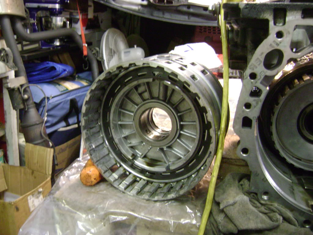
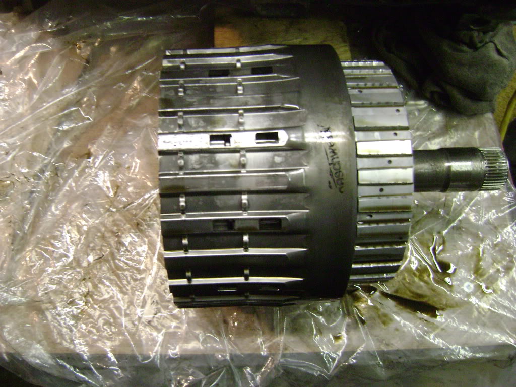
7. Pull outwards on the shaft, and the A and B drums will come out as one piece. Nothing will fall off, unless you've had a serious failure of the drum.

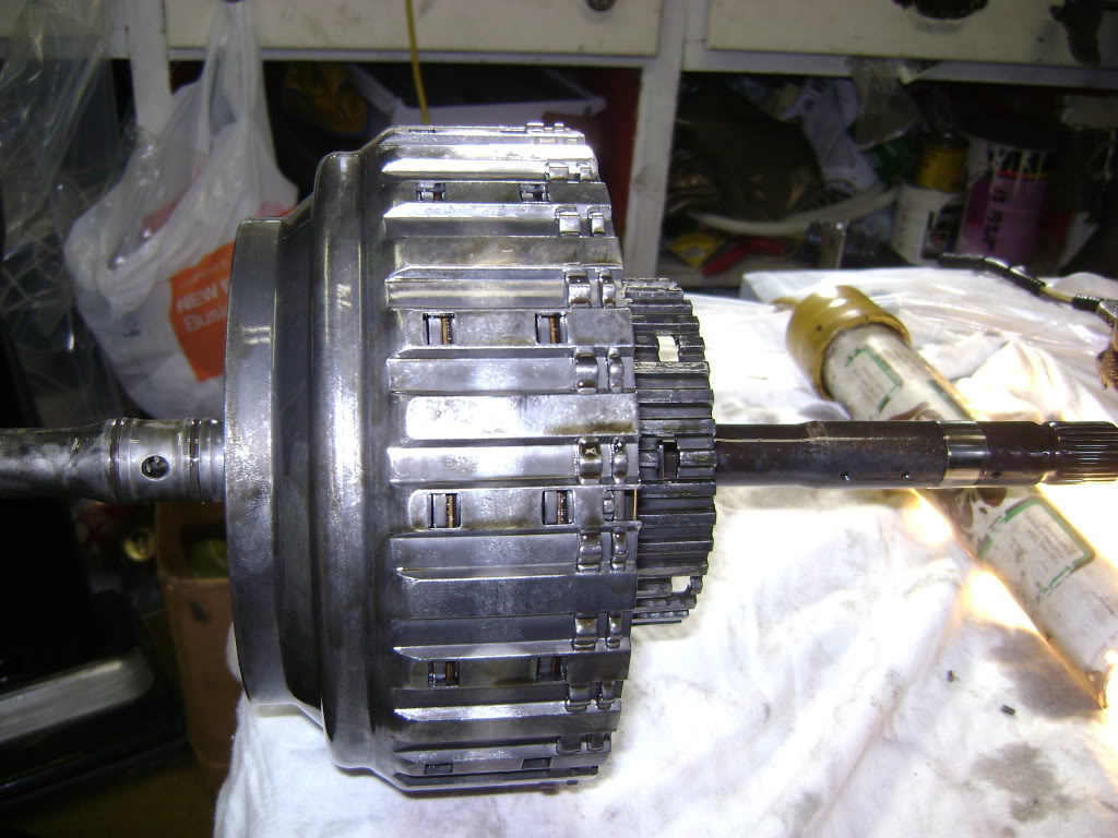
8. Take pictures and notes at every step, showing orientation, spacing, gaps, everything. You'll be glad later as you try and remember how it goes together.
9. Print out the ZF manual and use it as a checklist, checking off every step as you accomplish it. Notes on wear or damage is good too.
10. You'll need a bunch of boxes, use a separate one for each assembly and label them. I used a plastic box with a bunch of small compartments (like a tackle box or jewelry box) and I labeled each compartment as to what those bolts or screws were for. Organization is key here.
11. Watch out for bearings and spacers falling out, they love to do that!
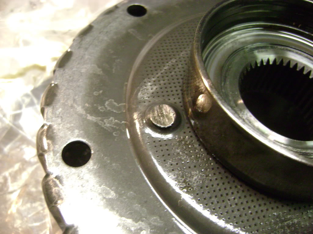
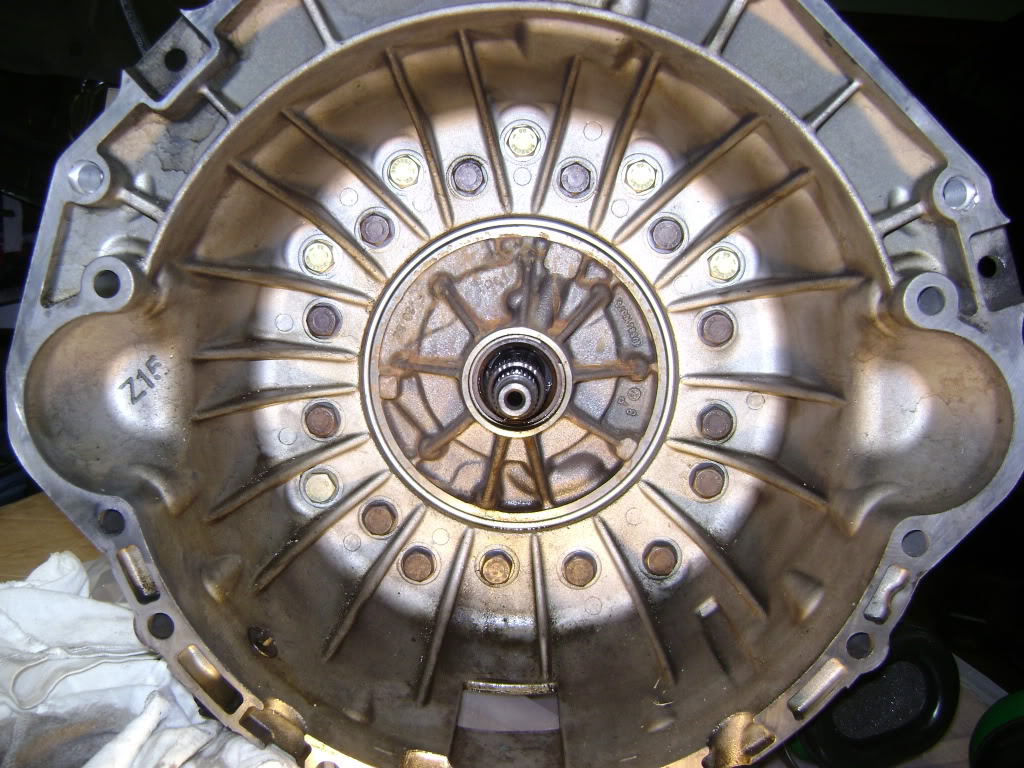
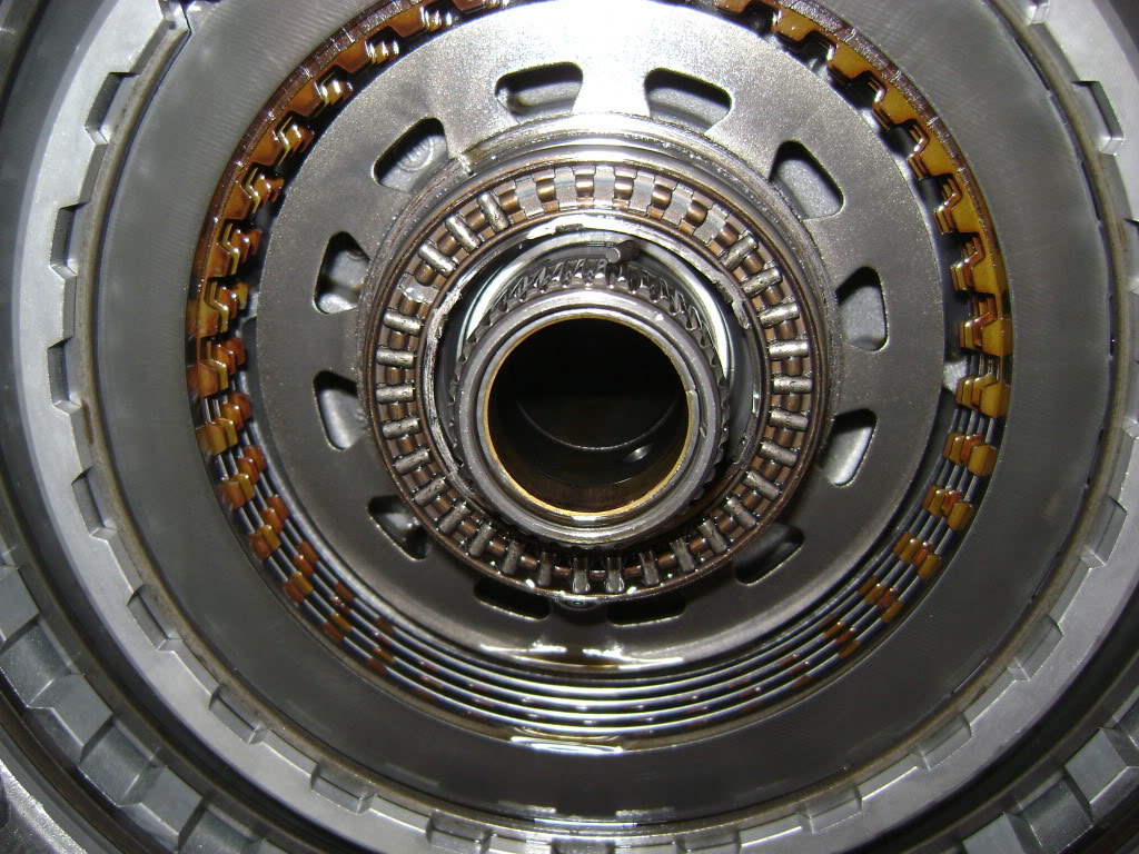
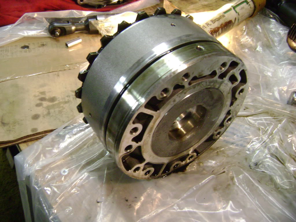
12. This is what your C drum looks like, and there's the bearing that fails.
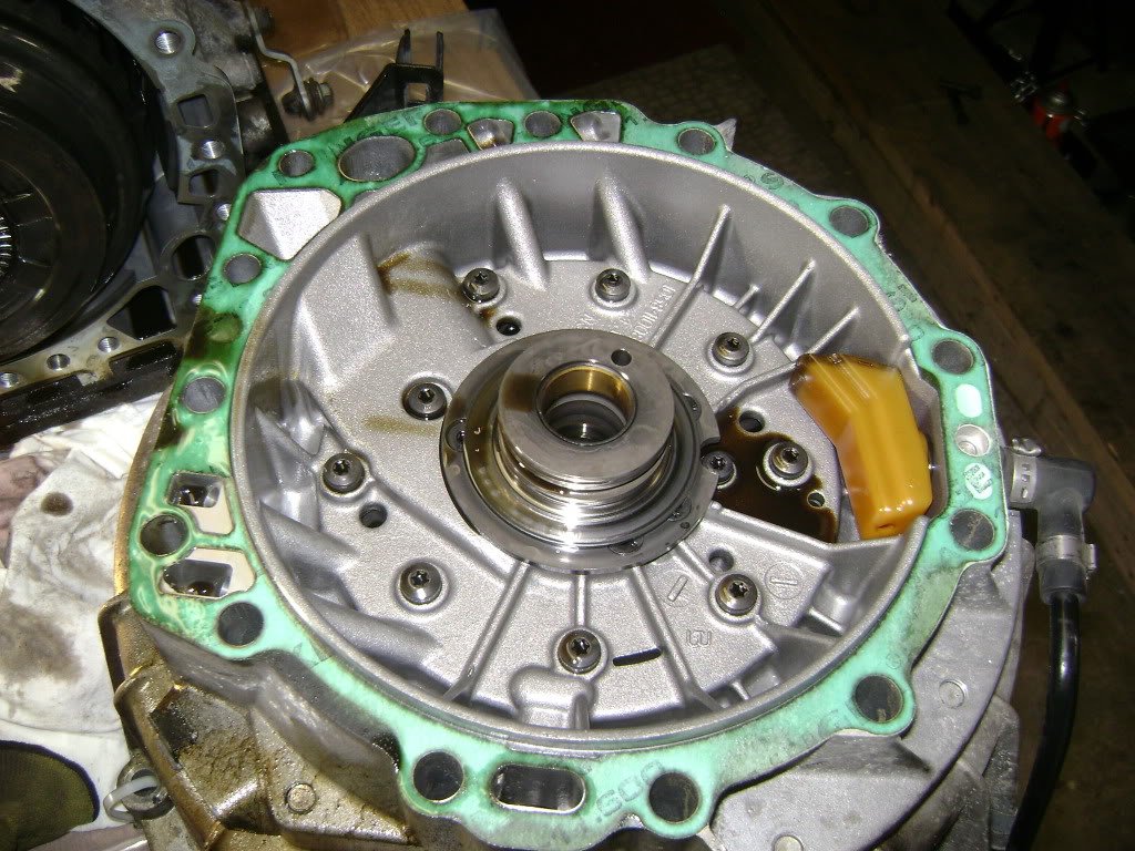
13. Undo the big snap ring and the drum pulls out. There's a lot of these big rings and your basic slotted screwdriver works great.
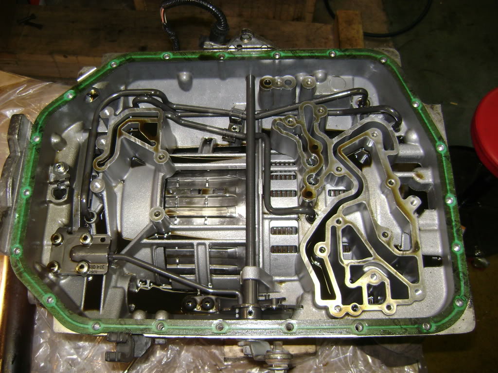
Then you will see the D and E drum assembly, but it won't budge until you pull the pan off and remove the oil pipes.
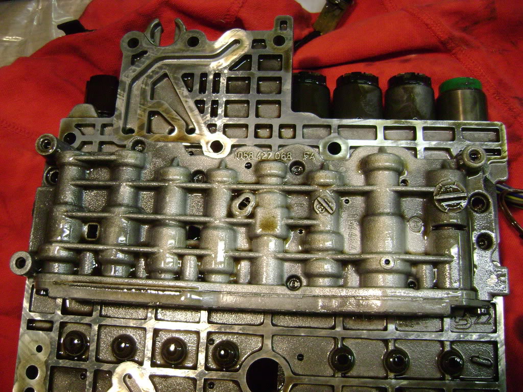
14. Pull the big headed screws out (22 of them, 17 are one size and 5 another). Leave the little screws in, or the valve body will fall apart. Remove the big plug on the side, and both speed sensors. and the whole thing comes off.
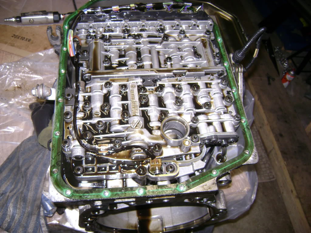
15. There's one screw holding the oil pipes down, you'll have to pry the pipes straight up, they aren't that tight. Do not pry on the valve body sealing surfaces.
16. the sealing rings for the drum come out with a pick (buy a set of these). The rings are in the rebuild kit, have a look and you'll see what you're trying to pull out.
8. Take pictures and notes at every step, showing orientation, spacing, gaps, everything. You'll be glad later as you try and remember how it goes together.
9. Print out the ZF manual and use it as a checklist, checking off every step as you accomplish it. Notes on wear or damage is good too.
10. You'll need a bunch of boxes, use a separate one for each assembly and label them. I used a plastic box with a bunch of small compartments (like a tackle box or jewelry box) and I labeled each compartment as to what those bolts or screws were for. Organization is key here.
11. Watch out for bearings and spacers falling out, they love to do that!
12. This is what your C drum looks like, and there's the bearing that fails.
13. Undo the big snap ring and the drum pulls out. There's a lot of these big rings and your basic slotted screwdriver works great.
Then you will see the D and E drum assembly, but it won't budge until you pull the pan off and remove the oil pipes.
14. Pull the big headed screws out (22 of them, 17 are one size and 5 another). Leave the little screws in, or the valve body will fall apart. Remove the big plug on the side, and both speed sensors. and the whole thing comes off.
15. There's one screw holding the oil pipes down, you'll have to pry the pipes straight up, they aren't that tight. Do not pry on the valve body sealing surfaces.
16. the sealing rings for the drum come out with a pick (buy a set of these). The rings are in the rebuild kit, have a look and you'll see what you're trying to pull out.
Last edited by avt007; 01-31-2012 at 07:02 PM.
#31
01-31-2012, 06:12 PM
17. There's a short shaft that just pulls out by hand.

18. The D and E drum will now come out, but is a tight fit, and will constantly jam as it gets cocked in the bore. Don't lose the two located dowels on the side.
19. Grab the shaft and pull, out comes the planetary gear assembly. It is heavy,and the little gear in the middle will fall out.
20. All you have left is the F clutch, and you'll have to take the back end apart for that.

21. Pull the gear and spacer off.
22. Stand the transmission on it's nose, and remove the countersunk bolts. They are tight, you'll need an assistant to hold the transmission while you do it.
18. The D and E drum will now come out, but is a tight fit, and will constantly jam as it gets cocked in the bore. Don't lose the two located dowels on the side.
19. Grab the shaft and pull, out comes the planetary gear assembly. It is heavy,and the little gear in the middle will fall out.
20. All you have left is the F clutch, and you'll have to take the back end apart for that.
21. Pull the gear and spacer off.
22. Stand the transmission on it's nose, and remove the countersunk bolts. They are tight, you'll need an assistant to hold the transmission while you do it.
Last edited by avt007; 01-31-2012 at 07:10 PM.
#32
01-31-2012, 06:14 PM
#33
01-31-2012, 07:10 PM
Veteran Member
#34
02-01-2012, 04:50 PM
Right! Clutches and drums and things. All of the units from A to F come apart basically the same way. Either a large snap ring in the outer wall of the drum, or the famous clutch spring in the bottom of the drum.
Again, use the ZF manual, they have step by step instructions on disassembly. I'm here to provide colour pictures and tips on how to do it without all the special tools.
EDIT: Here's something that worked great for me- drill a hole in your workbench big enough to fit the shafts on the A and B drums. My vise is small and awkward and I did the hole method to give me the "holding fixture" ZF keeps talking about.
I've left out some of the details, honestly I'm doing this because I have to, I didn't set out to build a DYI post! That's why I didn't take pictures of a lot of the drum disassembly. It's all the same anyway; take one piece off at a time, keep it in order, replace the o rings, clean the pieces, put them back together the way they came apart.
The A/B drum assembly comes apart with a big snap ring, then it just pulls apart from there. You should now have a series of drums with clutch packs in them. Again, take out the big snap ring.

Lift out the clutch pack all at once and keep it as a unit. Note the orientation so you don't try to put it in upside down. The big thick plate always goes on the top where the snap ring is.
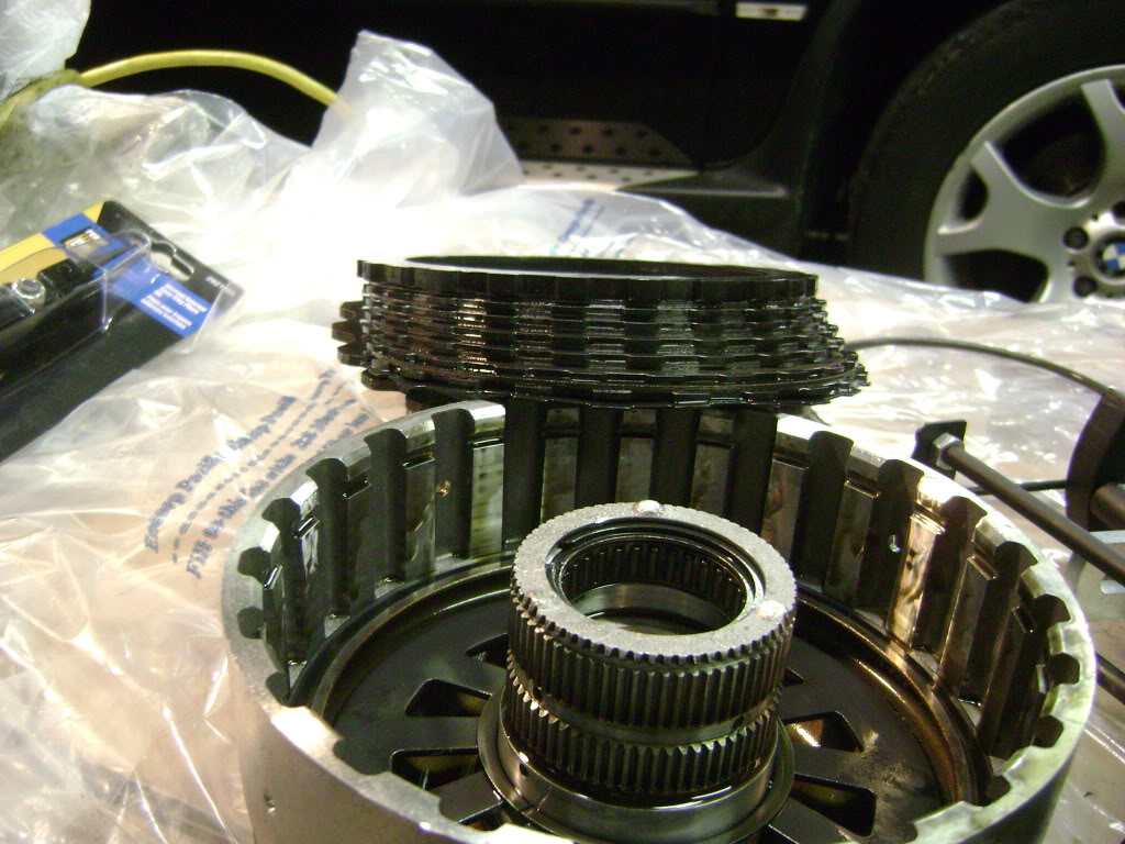
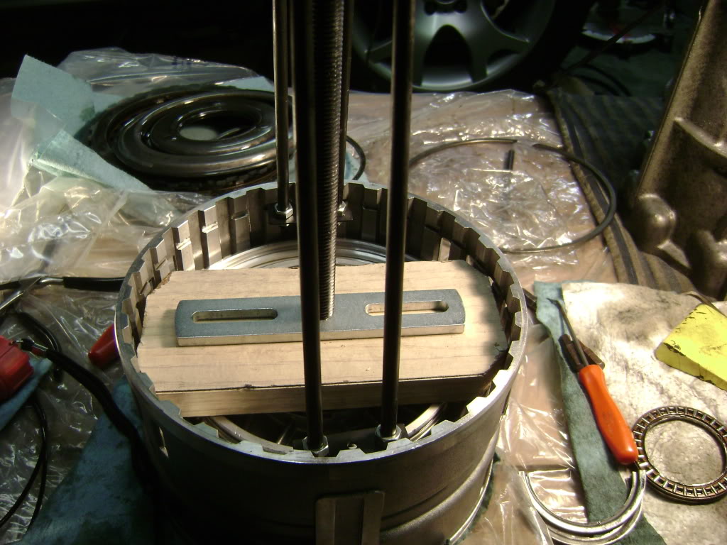
Each drum then has a spring that is circular and has many fingers facing the centre of the drum. Those fingers are trapped under either a small snap ring or a pair of retaining collars.
The springs are bloody strong, and despite what the ZF manual makes it look like, I could not budge them by hand.
I purchased this tool at Princess Auto, the Us equivalent perhaps would be Harbor Freight. I have seen this tool on ebay for $125, but I got it on sale for $27!
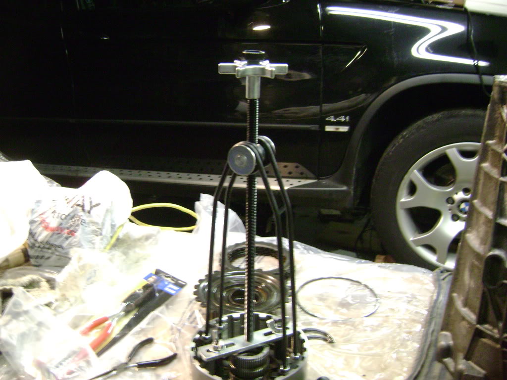
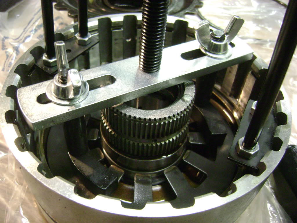
You can see that it has adjustable feet that press down on the springs and it pulls up on the groove where the snap ring lives. It works like a charm on some drums, and hardly at all on others.
Again, use the ZF manual, they have step by step instructions on disassembly. I'm here to provide colour pictures and tips on how to do it without all the special tools.
EDIT: Here's something that worked great for me- drill a hole in your workbench big enough to fit the shafts on the A and B drums. My vise is small and awkward and I did the hole method to give me the "holding fixture" ZF keeps talking about.
I've left out some of the details, honestly I'm doing this because I have to, I didn't set out to build a DYI post! That's why I didn't take pictures of a lot of the drum disassembly. It's all the same anyway; take one piece off at a time, keep it in order, replace the o rings, clean the pieces, put them back together the way they came apart.
The A/B drum assembly comes apart with a big snap ring, then it just pulls apart from there. You should now have a series of drums with clutch packs in them. Again, take out the big snap ring.
Lift out the clutch pack all at once and keep it as a unit. Note the orientation so you don't try to put it in upside down. The big thick plate always goes on the top where the snap ring is.
Each drum then has a spring that is circular and has many fingers facing the centre of the drum. Those fingers are trapped under either a small snap ring or a pair of retaining collars.
The springs are bloody strong, and despite what the ZF manual makes it look like, I could not budge them by hand.
I purchased this tool at Princess Auto, the Us equivalent perhaps would be Harbor Freight. I have seen this tool on ebay for $125, but I got it on sale for $27!
You can see that it has adjustable feet that press down on the springs and it pulls up on the groove where the snap ring lives. It works like a charm on some drums, and hardly at all on others.
Last edited by avt007; 02-01-2012 at 05:38 PM.
#35
02-01-2012, 05:00 PM
The C drum for example has a spring of such a big diameter (6 inches roughly) that the tool wouldn't fit and I had to improvise.

Another drum (F?) had two retainers that were VERY difficult to get in and out because of the big clumsy feet on the tool. I see that the ZF tool has thin flat feet. Anyway, I made it work, but I'd buy a different tool if I were you. Google "clutch spring compressor" and you'll see there's lots out there.
Once the spring is out you have a piston that engages the clutch plates. You can blow them out with air but I found you can just pull them out or turn the drum upside down and tap it on the bench.
Most of the pistons have replaceable o rings but some are built in. Piston F has a new design, but mine looked fine and I put it back in. Change the o rings, put the spring back in, throw the clutch plates in, snap ring, you're done.
Of course while you've had everything apart you inspect everything very closely under a bright light, looking for cracks, wear, bits of metal, etc.
Last edited by avt007; 02-01-2012 at 05:23 PM.
#36
02-01-2012, 05:23 PM
More notes on the ZF manual- they keep using a hoist assembly to remove and install the "towers".
It makes perfect sense in the factory, but it's not necessary. Everything comes out easily by hand, but it's the assembly that is slightly trickier.

As you put bits back in, you need to line up the grooves on the drums with the clutch plates on the adjacent drum. In a perfect world, you'd do that on the bench, then install the whole works at once, so you know everything is engaged, etc.
Problem is, the assemblies weigh a ton, and no way are you doing that on your own.
I just muddled through as you'll see. it was no big deal.
The only "special tool" I bought was the spring compressor.
Start assembly with your beautifully cleaned housing. Slide the F drum assembly in. The manual says use a dowel to line it up. You don't need it. Just note where the oil supply hole is and how it is lined up in the case and put it in. There is only one possible way to bolt this in, you can't screw it up. The bolt pattern ensures this.
Put the out put shaft in, the short one with the gears on it.
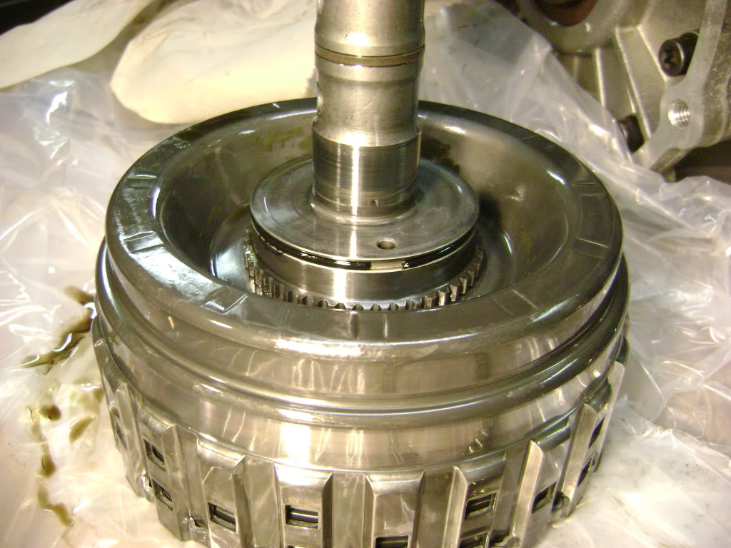
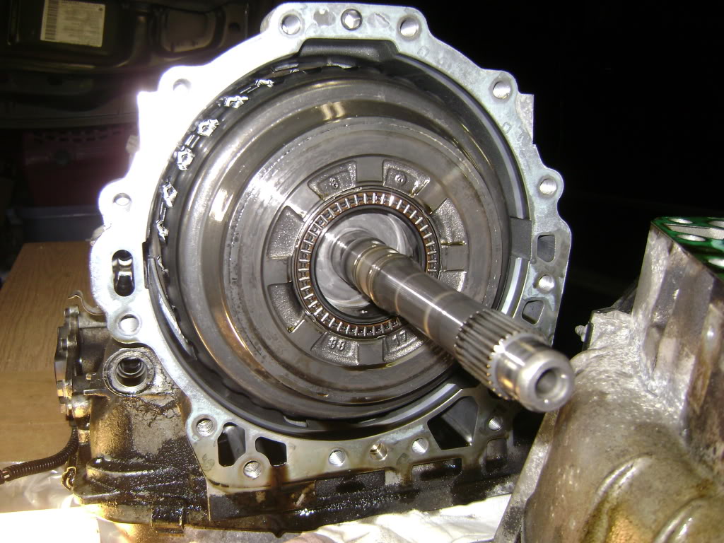
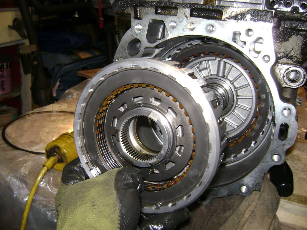
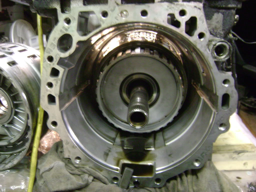
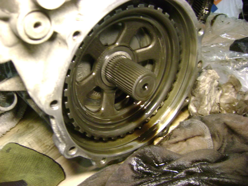
Slide the planetary gear assembly in. This is a bit of a bugger as it is quite heavy, and you'll have to wiggle and turn the shafts and fiddle until it lines up. It ought to look like this. (Except cleaner)
NOTE: There is a washer and a bearing that have to be in place before the D and E drums go in. Put the washer on the planetary piece, and the bearing on the D/E drum.
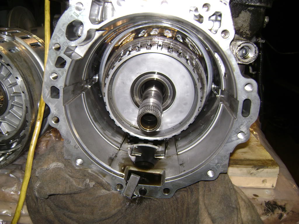
The D and E drum assembly now goes in. The loose plates in the E drum have to line up with the drum on the planetary gear assembly. Line the plates up first using an Allen key or something, then slide it in.
Make sure you have the locating blocks on either side. They will guide the assembly home. It will be tight as it was coming out, a dead blow hammer works nice here.
You'll know it's all the way in when the oil feed bores line up, and the oil pipe will go in.
It makes perfect sense in the factory, but it's not necessary. Everything comes out easily by hand, but it's the assembly that is slightly trickier.
As you put bits back in, you need to line up the grooves on the drums with the clutch plates on the adjacent drum. In a perfect world, you'd do that on the bench, then install the whole works at once, so you know everything is engaged, etc.
Problem is, the assemblies weigh a ton, and no way are you doing that on your own.
I just muddled through as you'll see. it was no big deal.
The only "special tool" I bought was the spring compressor.
Start assembly with your beautifully cleaned housing. Slide the F drum assembly in. The manual says use a dowel to line it up. You don't need it. Just note where the oil supply hole is and how it is lined up in the case and put it in. There is only one possible way to bolt this in, you can't screw it up. The bolt pattern ensures this.
Put the out put shaft in, the short one with the gears on it.
Slide the planetary gear assembly in. This is a bit of a bugger as it is quite heavy, and you'll have to wiggle and turn the shafts and fiddle until it lines up. It ought to look like this. (Except cleaner)
NOTE: There is a washer and a bearing that have to be in place before the D and E drums go in. Put the washer on the planetary piece, and the bearing on the D/E drum.
The D and E drum assembly now goes in. The loose plates in the E drum have to line up with the drum on the planetary gear assembly. Line the plates up first using an Allen key or something, then slide it in.
Make sure you have the locating blocks on either side. They will guide the assembly home. It will be tight as it was coming out, a dead blow hammer works nice here.
You'll know it's all the way in when the oil feed bores line up, and the oil pipe will go in.
Last edited by avt007; 02-01-2012 at 05:32 PM.
#37
02-01-2012, 05:30 PM
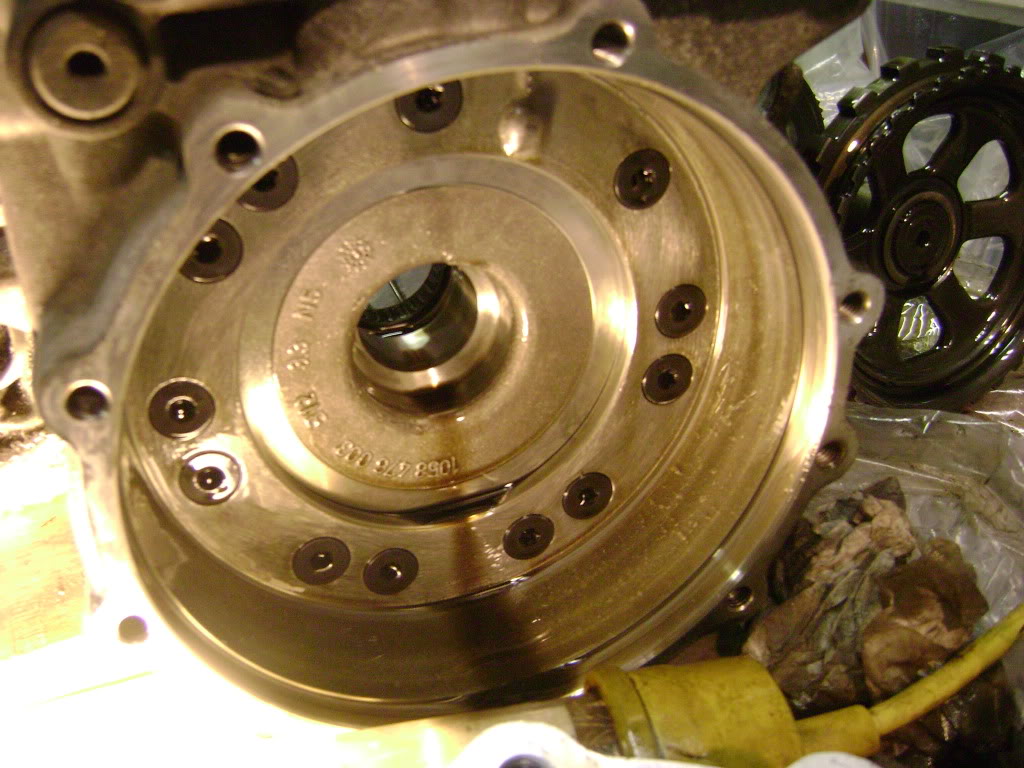
Now you have the C drum to install. Same old thing, line the plates up first and push it in. The C drum should have the shaft install already if you followed the book.
Not how many plates there are on the drum. By watching the top of the transmission, you can see how each plate will start to turn as you get each one lined up.
From the end of the shaft to the highest point on the C drum should be approximately 22mm.
That's as far as I've gotten, waiting on back ordered parts. I cleaned the oil pan and magnets, next is inspecting the Valve body.
Last edited by avt007; 02-01-2012 at 05:34 PM.
#38
02-01-2012, 08:41 PM
I did some looking at a colour cutaway drawing of the transmission, and the actual parts and here's what I suspect:
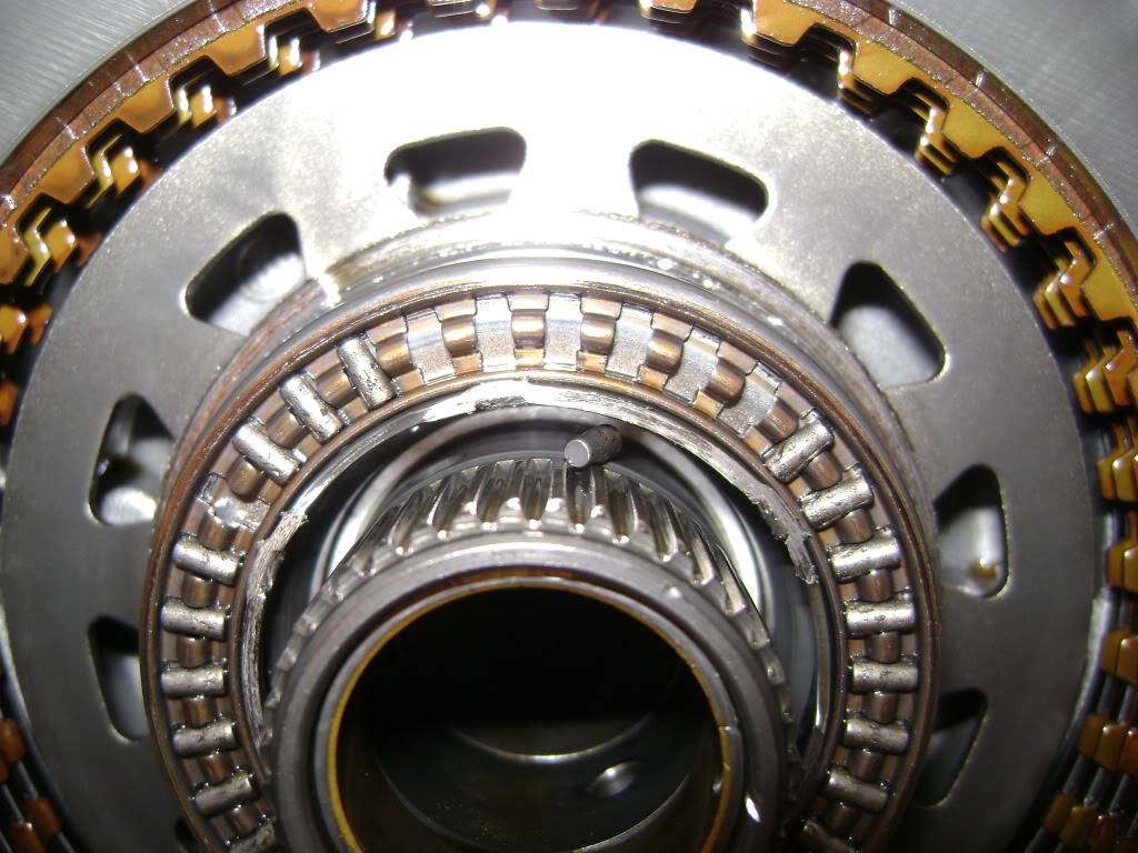
1. The bearing (item number 02.240) wore out, I don't know why. This allows the entire "Tower 1" assembly to move aft. I know it was aft because of rubbing found in two different areas.
2. Because of this movement, an o ring located behind the A drum migrated off the edge of it's sealing surface and dumped pressure from the A clutch.
This o ring was broken when I took things apart. I am hoping that a new bearing and all new o rings are the cure.
#39
02-01-2012, 08:56 PM
Veteran Member
I can only tell you what I have been told and that was if the bearings were missing or worn the pressure from the pump will be reduced. The reduced pressure will cause the shifting into first to be delayed and that causes the slippage. I was also told that this was a common problem with the ZF. A broken “O” ring did not do your shifting any justice. I am no expert with transmissions but I think you are doing a bang up job.
#40
02-01-2012, 09:21 PM