When you click on links to various merchants on this site and make a purchase, this can result in this site earning a commission. Affiliate programs and affiliations include, but are not limited to, the eBay Partner Network.
Recently, as happens with many x308's of this age, my third brake light fell off the rear glass, and basically disintegrated when I tried to open it. It's in a vulnerable spot where the glass focuses all the sunlight on that one spot, so it's not a huge surprise.
On top of that, the bulb holder/reflector assembly had warped into a banana shape and started to get poor conductivity at certain bulbs, so bulbs would not light even if they were replaced. That, and it was starting to crack and barely staying in the red lens...
Looking around on Ebay, I saw many replacements listed in a similar disintegrated condition, asking for hundreds of dollars. A few maybe cheaper, but I figured they would inevitably meet the same fate as mine. So I did what any completely reasonable person would do, and spent about an equivalent amount on supplies, and many hours, to make it myself. I decided to leverage existing CAD skills, some new electronics skills I'd picked up from work, and my ability to learn things by clicking around until software behaves the way I want it to.
With that in mind, onto the project:
Goals and constraints:
1. The new assembly should look OEM, or very similar. No cheap string-of-pearls LED strip taped to the glass, no crazy Tesla-esque full width brake light across the top of the glass, etc.
2. Reusing existing mounting points, and the factory connector. This should be a drop-in that anyone could in theory swap in.
3. Reusing the existing red polycarbonate lens/diffuser. It helps design and meet point 1, and is in perfect condition.
4. Replacing the incandescent reflector assembly with LED's. Something that can be replaced if needed, unlike those reflectors. Preferably with better heat tolerance/management.
5. The LED's in 4 shall not blind. Use current regulation to reasonably match brightness to OEM, maybe only a slight boost.
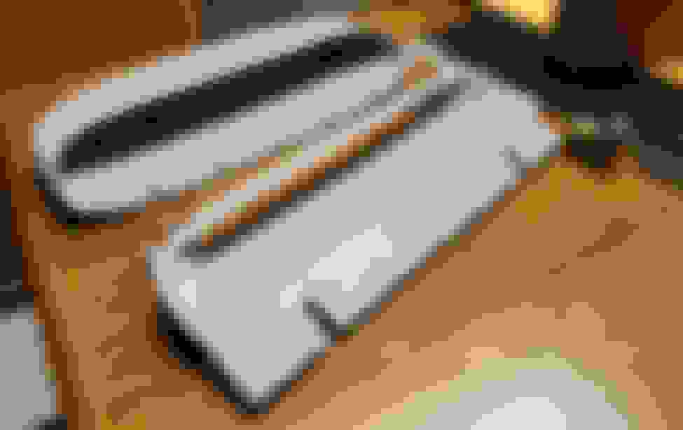
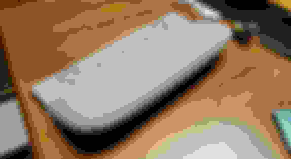
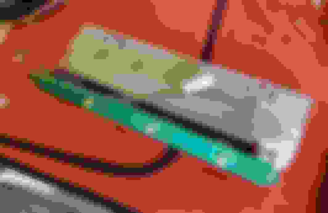
The first thing I worked on was the physical housing. At first I designed it to just hold the existing red lens and incandescents, just to get me by until the design is more fleshed out. The main housing (part that mounts to the glass and holds the lens) wasn't too difficult, though getting the oval-like shapes to sweep was finicky. Even then, the front is flat for ease of printing, while the glass is curved. This is an issue I'm going to get back to figuring out before the next revision, for now I've been stuffing foam in to keep it more secured. After a lot of screwing around I was able to design a rear cover which followed the style of the original, and mated up to my main housing. It screws on rather than clipping in. I'm going to go back and redesign this along with the main body, designing intermating parts is still relatively new to me, and the cover needs more optimizations for printing, as it's already a difficult part to print.
And also difficult to photograph. It's only grey because it's what I had in my printer, I'll redo in black eventually.
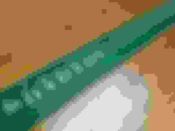
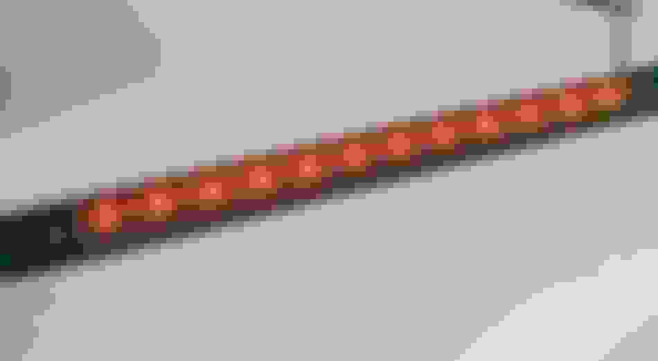
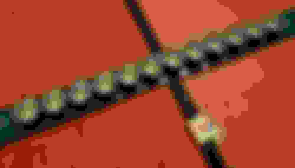
As for the lighting side of things, I bought a few different colors of red and white LED's to test out the color and appearance in the housing. I didn't want it to look like an obviously red LED if I could help it. I ended up going with a 625nm red LED, the most common ones... It wasn't a perfect match to the incandescent, but it was close enough and not worth getting white over it. I also tried a few different varieties of TIR optics to spread the light out, fill the housing, and direct light where it's needed. Then I designed a PCB to line up with the mountings in my housing. Those parts just arrived, I need to assemble and them later this week, but for now a teaser on it...
That�s awesome! The only other challenge I can think of is the 2 rubber bumpers where it rests on the glass. I know when I bought a new third brake light assembly about 7 or so years ago, the new light came with these pos flimsy bumpers. I ended up taking the ones out of the old broken assembly and transferred them over to the new one. I wish there was a source that remotely mimics the originals. Keep up the good work and I look forward to the next update.
PCB is assembled and tested, mostly done. I'm still playing with the brightness a bit, I decided the initial current setting was too bright so I've toned it down a good bit... I'll see how I feel about it.
LED's soldered and tested Optics in PCB fitted to enclosure. The optics clips managed to fit perfectly in the OEM lens, the clips on the sides just press on the plastic without force or interference.
Twilight shot
Been tweaking different materials and settings on the 3d printer too. I think I managed to get my design to a "seamless" two-piece design, all I had to do was take a different approach to the shell design and redefine every single feature in the model. But for now, I've got an earlier design in black PETG put in to see how it holds up to sunlight (no photos of that one yet). Also tweaked the angle so the lens points a little above horizontal, previous design was pointing slightly downwards.
So smooth
A2B, what are these rubber bumpers you mention? My OEM light didn't have any bumpers, it only had some plastic ribs that pressed against the glass by the mountings. I ended up putting some anti-rattle tape against them so they wouldn't rattle/sqeuak against the glass.
I've had to re-glue the little mounting tabs to the glass. After a couple of those, I stuffed a little wedge of foam under my housing to give it a little more support. Its barely noticeable but would be nice if it looked like it was supposed to be there. If I were designing this, I'd print a little "stand" on the bottom so that the tabs on the glass didn't have to support the weight, only secure it in place. But I only wish I had the time (i.e. retired). Would you eventually be putting these up on Shapeways or such that others could order them and DIY or planning to manufacture yourself?
I've had to re-glue the little mounting tabs to the glass. After a couple of those, I stuffed a little wedge of foam under my housing to give it a little more support. Its barely noticeable but would be nice if it looked like it was supposed to be there. If I were designing this, I'd print a little "stand" on the bottom so that the tabs on the glass didn't have to support the weight, only secure it in place. But I only wish I had the time (i.e. retired). Would you eventually be putting these up on Shapeways or such that others could order them and DIY or planning to manufacture yourself?
The support leg is an interesting idea, I might have to consider it. Maybe I'll design in some mounting points to the main body so it can be added on after the fact.
Once I'm happy with the design and it's completed, I'll probably put it up on Thingiverse or somewhere for free so anyone can contract it out (or print themselves if desired). As for the PCB's I'm not sure, I guess I could release the Gerber files and BOM so that anyone can order the boards and components themselves (or again contract out PnP), but I think for most people SMT assembly is a little bit different of a ball game from 3d printing. There's a small bugfix I'd do to the PCB design for thermal dissipation before releasing it, but that should be easy.
A2B, what are these rubber bumpers you mention? My OEM light didn't have any bumpers, it only had some plastic ribs that pressed against the glass by the mountings. I ended up putting some anti-rattle tape against them so they wouldn't rattle/sqeuak against the glass.
It�s the 2 black rubber bumpers contacting the glass. They look like eraser heads.

 02-06-2023, 08:44 PM