When you click on links to various merchants on this site and make a purchase, this can result in this site earning a commission. Affiliate programs and affiliations include, but are not limited to, the eBay Partner Network.
My upper tensioners have been replaced with third gen metal body tensioners by a previous owner, but I’ve discovered that the lower guides and tensioners have not been replaced. I’m not having any issues, but I’m going to take the front cover off and do the job correctly sometime soon, so that I don’t have a problem later. There are a ton of threads on this topic, and I’ll use them as a how-to when the time comes.
The engine has 180,000 miles on it. 1998 XJR, AJ26 engine, runs perfect, uses no oil. I just have a few general questions while I figure out what I’m doing:
1. Christopher’s Foreign Car Parts seems to be a favorite timing kit supplier among forum users. I see that they offer a “high mileage” kit that includes sprockets as well as everything else related to the project. How difficult is it to replace the sprockets? I’m definitely a “while I’m there, might as well replace it” kind of guy, but I want to know what I should expect regarding the sprocket replacement. They LOOK fine, as far as I can tell, but “while I’m there….”
2. I found a thread that linked to a $45 kit on ebay to use for immobilizing the camshafts before taking the chains off. Does the crankshaft also need to be immobilized? Is there a special tool for that? It would seem to me that the crank would need to be immobilized too….?
The crankshaft does not need to be immobilized for timing purposes, but it does need to be immobilized for removing the harmonic balancer in order to remove the front timing cover. The specific harmonic balancer puller tool set is available at several places online for around $100 bucks free shipping. The bolt holding the harmonic balancer is VERY tight, it is torqued to approx 275ft lbs. https://www.ebay.com/itm/32483892738...MAAOSw9wNhZ9~H
You do need the timing kit which is around $40 bucks and also readily available online with free shipping, this kit contains tools that locate the camshafts and the crankshaft in the correct position for timing purposes. (Note, under no circumstances should anything in this kit be used to hold the crankshaft when removing the harmonic balancer) https://www.ebay.com/itm/25503793750...gAAOSwqglg3twq
It would be easy to replace the sprockets, they have to come off during the repair anyway. But whether they need to be replaced is another matter, I doubt you will see any signs of wear on these even at 180,000 miles, but if you wanted to err on the safe side you could replace them.
The crankshaft does not need to be immobilized for timing purposes...
This is incorrect, The crankshaft position sensor must be removed and the Crankshaft Holding Tool inserted into the flex plate in the correct slot so the crankshaft and camshafts are correctly timed. There have been many people who have assumed the camshafts are timed with the crankshaft at TDC, which is also incorrect.
In addition, the crankshaft should not be rotated in an anti-clock direction when viewed from the front of the vehicle as damage to the rod and main bearings is the result.
Thank you both. So the crankshaft holding kit works to hold the crankshaft during the removal, but don't use the camshaft kit for that purpose...is that what you're saying? I can see why you wouldn't want to use the cam kit for that.
Thank you both. So the crankshaft holding kit works to hold the crankshaft during the removal, but don't use the camshaft kit for that purpose...is that what you're saying? I can see why you wouldn't want to use the cam kit for that.
Yes, the crankshaft HOLDING tool, in combination with its associated puller, is used to hold the crankshaft while removing the harmonic balancer bolt (and of course replacing it)
The timing kit contains a LOCATING tool which is used to place the crankshaft at the correct position (45atdc) for attaching the camshaft locating tools.
What NBcat is stressing is that no rotational force should be placed on the crankshaft while the crank locating/positioning tool is installed, it is merely there to ensure the crankshaft is in the correct position for installing the camshaft tools. This crankshaft locating tool is installed where the crank positioning sensor is located, under the vehicle at the flywheel. The crank positioning sensor is removed and the crank locating tool is installed while any/all valve timing is performed. The crank locating tool is then removed and the crank positioning sensor replaced.
So the crankshaft holding kit works to hold the crankshaft during the removal...
Before you buy the crankshaft pulley holding tool, you need to make sure it is useable for SC engines. Many of the kits sold in plastic boxes are for NA engine shallower pulleys and will not suit the SC deeper pulley. You will need a holding tool which has a 90 mm long cylindrical part.
I install the crank-lock and cam tools to set up timing,
I remove the crank-lock and cam tools to remove the crank damper so as NOT to bend/break anything.
There is an extreme amount of force necessary to remove the bolt and then pull the damper forward slightly.
After the damper is removed, the locking tools are reinstalled to keep the crank/cams TIMED.
I worked at the dealer when the AJV8 was introduced. One of the mechanics in the shop needed to replace the cylinder heads and timing chains. (secondary broke and ruined a head)
He used the crank-lock tool to hold the crank while he removed the damper bolt.
He reinstalled all the components on the engine and it ran like $H!T.
We tried EVERYTHING to try to get it to idle properly. Kept getting CRANK/CAM fault.
The rest of us asked if he used the lock tool to hold the crank for bolt removal?
He insisted NO!!!!!!!!!!!
He finally pulled the gearbox to check the drive plate and there it was!!!!!!!!!!!!! The oblong timing/holding segment was BENT WIDE.
The sensor could not read the number and spacing of the segments correctly. (he was sick!!)
Went to the parts dept and the cost of a new AJ27 torque converter drive plate was EXPENSIVE.
Another mechanic in the shop said he had a junk engine for parts and offered the used flywheel.
It was bolted in and the gearbox reinstalled.
Engine ran normally and he finally admitted he must have used the locking tool to hold the crank.
He never lived it down and was reminded of this from time-to-time.
He did buy a few lunches for the guy that gave him the drive plate.
The tool is not to be used to hold the crank for disassembly but everyone seems to know better than to follow directions!!!!!!!!!!!!!!!
Good Luck
Not sure of this helps, but thought I would add it in........I did the replacement on my normally aspirated 98 VDP in 2006. No need to worry about timing as there was no change to any positioning that could affect it - that is why the locking tool. Pretty easy job and no special tools ordered, although I did "fabricate" the tools needed for the camshaft removal. I'm not sure how different the supercharged engine would be, but think not a lot. In those days the camshaft tool was $$$$ and my kluge was free. The Harmonic Balancer removal was done with a cheater bar made from a woodworking pipe clamp that fit between the rad and the engine and the Crankshaft lock used a piece of rod from my scrap bin with a bend in it to hold it in place. The job was done at ~104,000 miles and the car now has ~190,000 and no subsequent trouble. The following is from the notes I made at the job completion at the request of some other forum members. If doing it again, I would take the hood off to give better access as subsequent work showed removing it to be pretty easy, even as a 1 person job.
"This week I completed the replacement of primary tensioners, tensioner rails, guide rails and secondary tensioners plus associated gaskets and seals on my 98 VDP (104K miles). I got going on the job after I had removed the cam covers to replace the gaskets due to oil leaks around the spark plug seals. With the cam covers off, I could see cracks on both timing chain guide rails, so I decided to go ahead with the replacement of all the above parts. Once I had things apart I found both secondary tensioners and both primary tensioner rails had cracks as well. I’ve posted some photos in the photo album at the following link for those who are interested.
Some observations:
If it weren’t for my visual of the guide rail cracks, I wouldn’t have thought the job necessary as there were no noises or other indications of problems (although the cars mileage made it a candidate).
The total job took about 13 hours to complete which exceeded the shop time by a few hours. Most difficult was getting the harmonic balancer off. It took a couple of hours as the puller I used was fairly long which made getting it on straight in the space tricky. In all, 10 hours were spent removing and replacing components necessary to access the tensioners and rails.
I left the hood (bonnet) on the car & didn’t find it a great inconvenience.
Before the primary & secondary tensioners were off the car, it was impossible to tell if they were OK or not. As it was, the primary tensioners were OK, but both secondary’s were cracked in the same place. I’m guessing that the type of crack I found could become something that lets the tensioner piston escape from the body - leading to mayhem.
The secondary tensioners couldn’t be replaced without removing the camshaft sprocket to gain clearance. Once it was removed, the job was simple.
I built a couple of cheap & cheerful tools for the camshaft sprocket removal based on pictures of the Jag tools shown in AllData & using measurements I took from the engine. Time to create them was about an hour (included in the 13 hour total time) & they worked fine.
The primary tensioners, rails and guides were simple to replace and only required that the camshafts be rotated slightly to provide slack in the chains.
The guide rails on both sides had significant stress cracks. How likely this is to translate into catastrophic failure is anyone’s guess, but I would gauge the risk as high as the pieces that could have come off were large. NB that it appears that the rails are a metal core encased in a plastic/acrylic. The cracks are limited to the plastic portion.
Both primary tensioner rails had short hairline cracks in the same place (near the pivot point). Again, what risk this presents is open to question. Rail construction is as for the guide rails (plastic over metal).
I didn’t change the timing chains as all were fine with no sign of wear.
Overall assessment – a relatively easy job (& much easier than my recent front end rebuild). The only complicating part was the number of things that needed to be removed & reassembled to get at the tensioners."
Thanks everyone - very informative as usual. I think everything makes sense in my head and I'm going to order a crankshaft pulley holding kit designed for the s/c pulley depth along with the camshaft kit.
Two other questions that will probably answer themselves once I start on the project:
1. I assume the damper pulley holding tool will bolt to the pulley in an obvious way, but does the socket go through the center of the holding tool to loosen the damper bolt?
2. After the damper bolt is removed, I'll use the puller to pull the damper off the crankshaft. However, what holds the crankshaft from turning as I wrench on the puller bolt? Maybe the damper will slide off pretty easily with the puller, so the crank won't want to turn?
Thanks everyone - very informative as usual. I think everything makes sense in my head and I'm going to order a crankshaft pulley holding kit designed for the s/c pulley depth along with the camshaft kit.
Two other questions that will probably answer themselves once I start on the project:
1. I assume the damper pulley holding tool will bolt to the pulley in an obvious way, but does the socket go through the center of the holding tool to loosen the damper bolt?YES....................and that damper bolt is TIGHT 2. After the damper bolt is removed, I'll use the puller to pull the damper off the crankshaft. However, what holds the crankshaft from turning as I wrench on the puller bolt? THE TWO THREADED BOLTS THAT DO THE PULLING CAN BE USED TO PREVENT THE HARMONIC DAMPER FROM TURNING, IT WON"T BE A PROBLEM. (NOTE The damper bolt should not be reused, it should be replaced with a new one, which comes pre-coated with loc-tite).
Also note:
Once you have removed the damper bolt and you have broken the harmonic balancer loose using the puller, you should NOT keep pulling, rather you should slacken the puller bolt and tap the harmonic balancer back on to "release" the collar/collet. The harmonic balancer should then remove easily by hand.
This is incorrect, The crankshaft position sensor must be removed and the Crankshaft Holding Tool inserted into the flex plate in the correct slot so the crankshaft and camshafts are correctly timed. There have been many people who have assumed the camshafts are timed with the crankshaft at TDC, which is also incorrect.
In addition, the crankshaft should not be rotated in an anti-clock direction when viewed from the front of the vehicle as damage to the rod and main bearings is the result.
I’m starting the project this weekend. I have the cam covers off and I want to make absolutely sure I know which direction to rotate the engine as I’m locating the cam lobes and so forth. Looking from the front of the engine, the crank should be rotated CLOCKWISE only, is that right?
I plan to mock up the timing kit in the correct position first, then remove the timing kit before removing the harmonic balancer, then replace the timing kit once the balancer is removed. I’ll probably have more questions but I want to make sure of the rotation direction first. Thanks all!
Edit: one other question, when I remove the crankshaft position sensor, is there only one place that the crank lock tool will fit, or can it be 180 degrees off? Or 90 degrees for that matter?
Yes, rotate crankshaft clockwise looking from front.
There is only one special hole in the flex plate into which the crankshaft locking tool will fit. However, the crankshaft can be locked with the camshaft flats facing up or facing down. To have the correct lock, rotate the crankshaft until you see the camshaft flats approaching their top positions (top in relation to the cylinder head plane). I then positioned a remote borescope camera directed at the crank sensor opening so that I could watch (on my smartphone) the specially shaped opening in the flex plate (matching the locking pin) approaching. When this opening was close to the required position, I inserted the locking pin and pre-loaded it using a longer bolt with a spring on it. After very slowly turning the crankshaft a bit further, I heard a "click" when the locking pin popped in. Then replaced the longer bolt/spring with the original bolt.
Question: Which primary chain guides and tensioners did you buy? Any real info on the quality of the aftermarket alternatives?
I bought a chain, tensioner, and sprocket kit from Christopher's Foreign Car Parts based on recommendations from the Forum. I don't have the kit installed yet, but the quality seems good to me. It includes new gaskets for the timing chain and cam covers. It also includes a new harmonic balancer bolt with loctite on it, crankshaft seal, and a set of what seems to be pretty decent instructions.
Aquifer, do you have the secondary timing chain tensioners installed at least?
No, in fact I don’t have the harmonic balancer or the timing cover off yet. I’m planning to do that today. The secondary tensioners were replaced by a PO at some point in the car’s life, but I’ll replace them anyway when I get in there.
I do have a question that you might have some insight about: when I removed the left cam cover, one of the bolts fell out and I can’t find it. The bolts are sort of captive in the cover, and they all stayed in place except one. The whole grommet, bolt, and sleeve came out - not just the bolt itself - so it’s kind of bulky. I heard it fall, and I thought it landed under the car. It did not. My questions is this: is there ANY way it could have gotten inside the engine block itself? I sure don’t think so from the camshaft area, but maybe it fell down in the timing chain area. I can’t see very well inside the cam cover with a flashlight from the top. I think I’ll find it when I remove the cam cover, so maybe I should just be patient. If it fell down in there, I don’t think there’s a way it could have gotten back into the engine block, is there? It drove me crazy looking for it! It seems to be too bulky to get down past the timing chains, but maybe it did. Fun times!
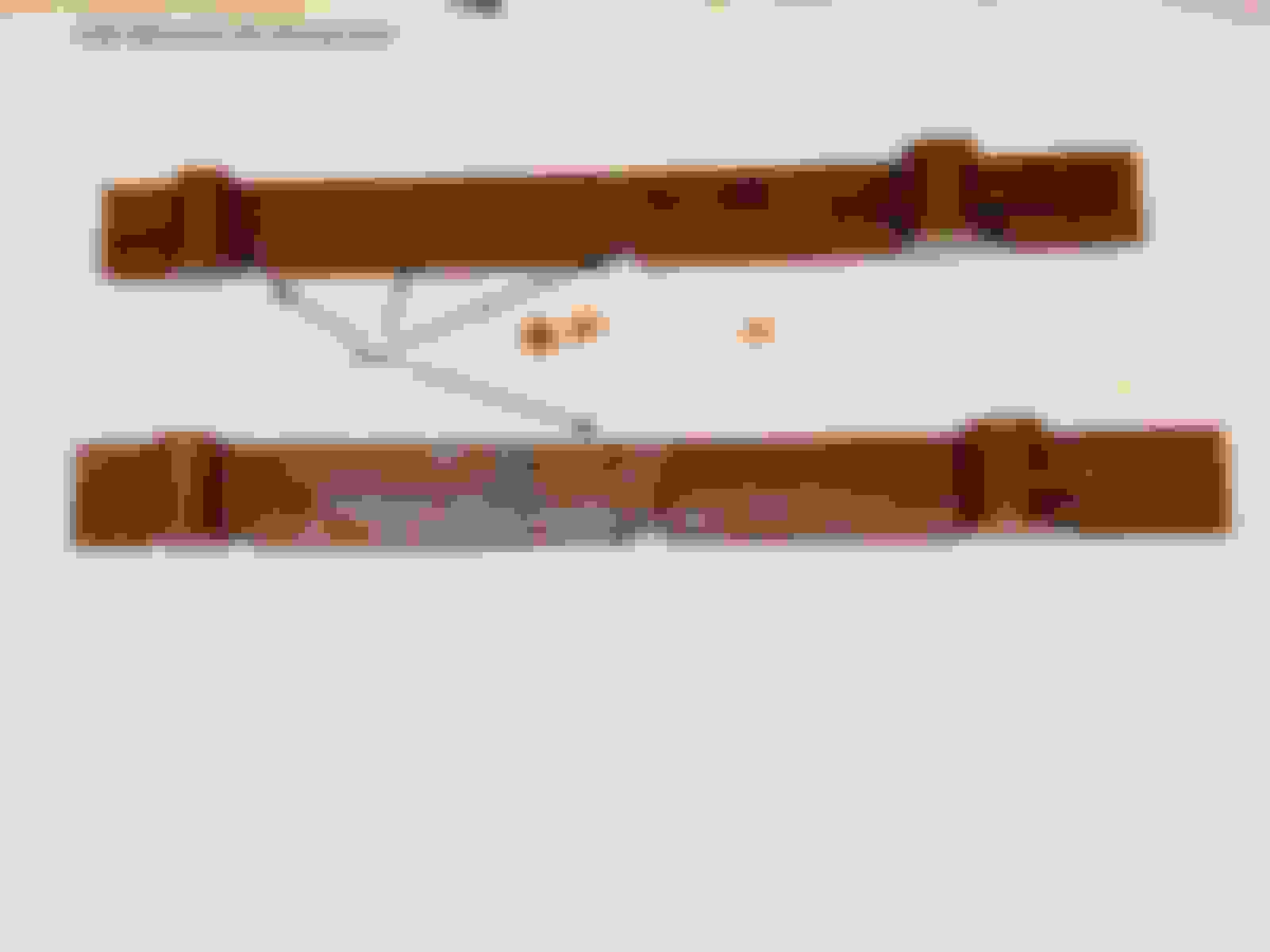
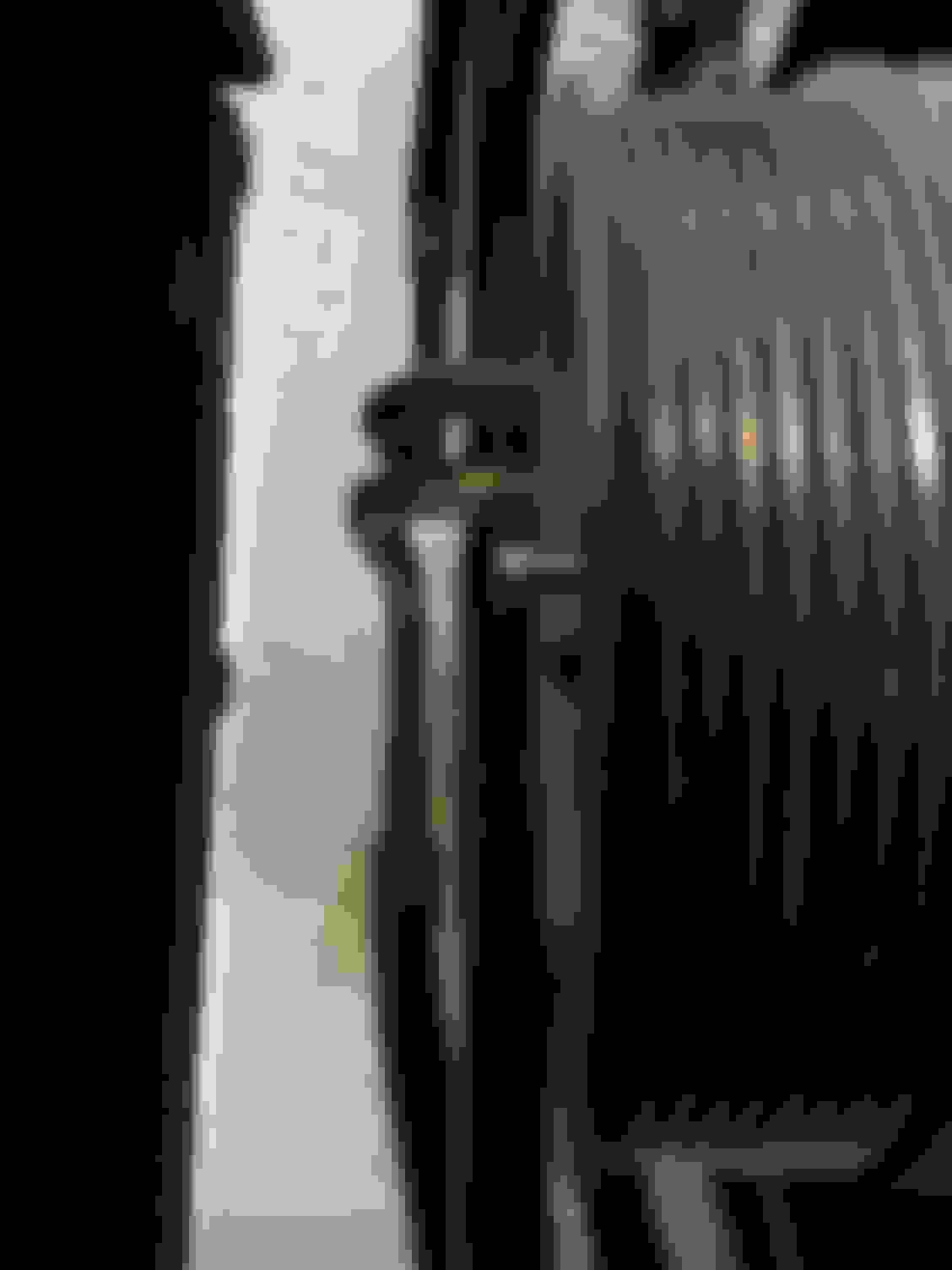
Ok, time to regroup. The harmonic balancer holder/puller kit that I bought is not correct. The spacer on the heavy duty holding tool is not deep enough. I ordered one for the supercharger pulley, but it’s not deep enough and the bolts are not long enough. Two questions come to mind:
1. Can I buy two steel spacers and longer bolts, or will it just break the bolts off when I bear down to break the pulley bolt loose? It seems like the spacer should sit flat all the way around to keep that from happening.
2. Does anyone have a link to the correct kit that you KNOW is the correct depth? The pulley depth measures close to 3”. My kit measures about 2.25” deep.
Obviously I should have measured the depth first, but the kit said it was for the supercharger pulley, so I didn’t. Any advice? Thanks again!
PS - On the other hand, I was able to successfully mock up the timing kit. I found the flat spot on the cams. I had to rotate the engine 180 degrees before I found the hole in the flex plate, but the holder tool fit perfectly. I removed the kit and started working on the harmonic balancer, when I discovered I don’t have the right kit to hold the pulley.
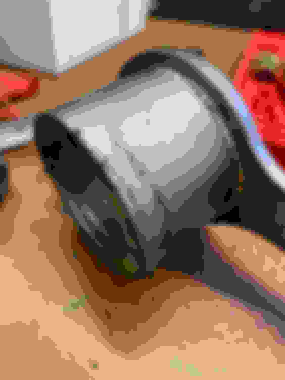
Here is a picture of one of the bolts without the handle installed. I got the threads pretty clean and then discovered the problem. The spacer needs to be 3/4” deeper, and the bolts need to be correspondingly longer. See second picture to be clear what I mean by spacer. You can sort of see the tape measure behind it. Needs to be 3” deep.

 10-20-2021, 01:58 PM